
4 minute read
International Journal for Research in Applied Science & Engineering Technology (IJRASET)


ISSN: 2321-9653; IC Value: 45.98; SJ Impact Factor: 7.538
Volume 11 Issue III Mar 2023- Available at www.ijraset.com
Advertisement
V. FABRICATION
This is the final and very crucial step of the project in which the fabrication and assembly of parts is to be done and hence after its completion, we have to do the analysis and testing of the project to overcome the failure. Fabrication of automatic stair climbing trolley is mainly divided into 2 components:
1) Driving System
2) Frame
After the purchasing of materials and required parts from the offline market in which few parts were not available so we looked them up in online stores and ordered them, after that we started the fabrication of trolley. Steps involved in the fabrication of different components and processes involved are as follows:
A. Driving System
Driving System mainly consists of following parts -
1) Timing Belts
2) Rectangular Base
3) Pulleys
4) Bearings
5) Axles
6) DC Motors (high torque)
7) Battery
Prior to beginning the creation we need to choose the aspects for rectangular base wherein the shafts and pulleys will be joined, however because of the limited length of crankshaft belts that are accessible in the market we picked the belt of greatest length that was accessible and likewise we chose the components of base, shafts and pulleys.
B. Frame
1) It is the second component of the trolley, where the load and weights are kept over it and it is attached to the driving system of the trolley.
2) It is foldable & convertible and can be kept at different angles of inclinations with respect to the driving system of the trolley.
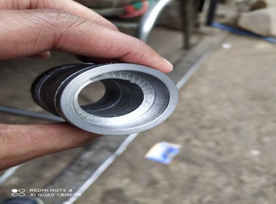
3) Initially we divided the circular pipe into 4 parts of required dimensions and then by using an electric cutting machine we purchased them from the market, after that we joined them together by Electric Arc Welding (EAW) as shown below.
4) After that we prepared another rectangular frame of required dimensions in the similar manner and joined both frames together perpendicular to each other.
5) Then we attached them with the base of the driving system along with two slotted clamps (in which one clamp is on right side and other is on left side) of the driving system so that we can change the inclination of the frame when needed.
6) After that we welded 3 iron sheets on the frame, so that we can support the weights over it and while climbing up & down weights will be in a safe position.
ISSN: 2321-9653; IC Value: 45.98; SJ Impact Factor: 7.538
Volume 11 Issue III Mar 2023- Available at www.ijraset.com
Table 1. Specification
Part name
Pulleys Polyurethane iron core
Steel sheet Stainless steel
Shaft Mild Steel
Battery Lithium ion ups battery (12V) - x 380mm x 22mm(Dia.)
Battery Charger Electric chargerDC Motor 30 RPM, Rated Torque(19kg-cm) 25.6mm(Shaft length),Gearbox Shape(Rectangle)
Hollow Bars Iron (Rectangular)
Hollow Rods Iron (Circular)
Belt Timing belt
Bearing Iron core ball bearings
Slotted Clamp Slotted iron strip x 10mm x 4mm
(Out. Dia.), 20mm (Inn. Dia.)
VI.CONCLUSION
However, this venture had a few impediments in regards to the strength and worked of the construction, it very well may be viewed as a little step in the right direction, all things considered. During the trial of this venture, it was understood that it wouldn't be an illconceived notion to think about this plan for conveying weighty burdens up the steps. This item will be very much acclaimed in the event that fitting the needs can be marketed. However, the underlying expense of the venture appeared to be higher yet more exact assembling would abbreviate this.
Taking everything into account, on the off chance that this item can be completely robotized and delivered at a cheaper the acknowledgment will be incredible. As of now, there are no contenders for such a sort of item in our market. This venture targets fostering a system for simple transportation of weighty burdens over steps. The requirement for such a framework emerges from everyday necessities in our general public. Gadgets, for example, hand streetcars are utilized to ease the pressure of lifting while on level ground; in any case, these gadgets normally fizzle with regards to conveying the heap over a short armada of steps. In the illumination of this, the venture endeavours to plan a step climbing wheel barrow which can convey weighty items up the steps with less exertion contrasted with conveying them physically. It likewise try's to concentrate on the business reasonability and significance of such an item.
VII. FUTURESCOPE
A. Use of a lighter metal for assembling of this item should be possible to significantly decrease oneself weight and cost.
B. In future in the event that necessary a similar driving framework can be utilized to change over this streetcar into programmed step climbing wheelchair for debilitated individuals.
C. A sensor and guiding wheel can be carried out to move around the steps. Sensor and engine would be a substitution of a manual power, which runs the casing wheel.
D. With the assistance of clock circuits, the vehicle could run over a foreordained step size flawlessly without utilizing any switch Single engine could be utilized to move over both the level and track of the steps.
References
[1] Sonu Kumar Krishnaprasad singh (2017). “Design & Fabrication of semi-automatic stair climbing trolley”, International journal of engineering science and computing,7(3);5619-5620.
[2] P.JayPraveenrajet.al.(2016).”Design and Fabrication of stair climbing trolley” ,International Journal of Advancement in Engineering Technology, Management and Applied sciences;3(5);89-102
[3] M.M.Mogaddam and M.M.Dalvand(2005),”Stair climbing mechanism for Mobile Robots, Tehran International Congress on Manufacturing Engineering; December 12-15,2005,Tehran ,Iran.
[4] A.S.Shirwadkar and S.K.Choudhary (2013),” Synthesis, Modeling , Analysis and Simulation of stair climbing mechanism;”International Journal of Mechanical Engineering and Robotic Research,;2(4);330-341.
[5] M.-S. Wang and Y.-M. Tu(2008) “Design and implementation of a stair-climbing robot,” in Proceedings of the IEEE International Conference on Advanced Robotics and Its Social Impacts, Taipei, Taiwan.
[6] Q. Zhang, S. S. Ge, and P. Y. Tao(2003), “Autonomous stair climbing for mobile tracked robots,” in Proceedings of the 9th IEEE International Symposium on Safety, Security, and Rescue Robotics (SSRR '11), Kyoto, Japan.

