7 minute read
An Innovative Design and Fabrication of Pneumatic Skate Scooter


Dr R Suresh1 , Barath S P2 , P Elanchezhian3 , M Mohan Sundar4
4Student, Mechanical Engineering, Vel Tech High Tech Dr Rangarajan Dr Sakunthala Engineering College No 60 Avadi-Vel Tech Road Avadi, Chennai-600062, Tamil Nadu, India
Advertisement

Abstract: It is difficult to get that compressed air can be used to drive the Automobiles. However that is true, and the “compressed air operated scooter” as it is popularly known, has Caught the attention of researchers throughout the world. It has carbon-free and is ideal for city driving conditions and economical friendly. Today all the vehicles are mostly conventional & non-conventional fuel produce large amount of harmful gases like CO2,NO2,SO2 etc. which can increase the global warming. In automobile & industrial work, the pneumatic system plays an vital role. MDI is one of the top Companies that hold the international patents for the Compressed air operated automobiles. Even though it seems to be an Eco- friendly solution. The electricity that requires for pollution in the long run. This vehicle is a potentially revolutionary personal transport system device. While developing this vehicle the control of air pressure and energy density requirement for output energy release and emission control have to be mastered for development of a safe, light weight and cost effective compressed air vehicle for upcoming features. The Compressing air has to be considered while figuring the overall Efficiency. In spite of that, the compressed air Automobiles will come up with the best reducing air.
Keywords: Air compressor, Battery, Pneumatic cylinder, single slider crank mechanism.
I. INTRODUCTION
We are living in a very well developed society. Now days we are using a fuel based vehicle or electric based vehicle to transportation or to travel for a short distance or long distance. It becomes regular and peoples are suffering from a price of fuel. Global warming is of the problem which affects the whole world and it creates impact to all over the world. The fossil fuels are using in various like thermal power plant, internal and external engines etc… To overcome this we use a compressed air vehicle. A compressed air vehicle (CAV) is powered by piston called pneumatic cylinder Which is stored in a compressor tank. A normal engine needs fuel and air for combustion to drive piston with hot gas expansion to power the vehicle, but in this compressed air vehicle (CAV) it only contains pneumatic cylinder to move the vehicle forward. Due to its limitation the power produce by pneumatic is less compared to the electric vehicle or fuel vehicles.
Compressed air vehicle (CAV) is based on the principle of single slider crank mechanism. This slider crank mechanism act as a connecting rod between the wheel and the pneumatic cylinder. The reciprocating motion of the pneumatic cylinder is converted into the rotary motion using the slider crank mechanism, which helps to rotate the wheel and moves in a forward direction or vice versa. By using the pneumatic cylinder we can move the vehicle without using electricity or fuel. This helps to reduce the carbon pollution and controls the usage of fuel. It also able to control the cost of fuel and electricity.by using of pneumatic cylinder and compressed air cylinder we are saving the cost, pollution and people would not suffered. However once the compressed air is released, the air will expand and can be used to move the pistons power the engine or a host of other functions.
II. METHODOLOGY
On analysing various research journals, for doing our project on design & fabrication of pneumatic skate scooter we follow stages below,
1) Design Preparation
2) Literature survey
3) Material Acquisition
4) metal Cutting and Drilling
5) Welding
6) Calculation
7) connecting circuits
ISSN: 2321-9653; IC Value: 45.98; SJ Impact Factor: 7.538

Volume 11 Issue II Feb 2023- Available at www.ijraset.com
8) Trail & error
9) Finishing
A. Problem Identification
1) Problem Statement: The workforce is a key component in the lengthy process of fabrication. Equipment, factory overhead, supplies, commitment, teamwork, product complexity, and cooperation are a few additional aspects that have an impact on the quality of the fabrication process.
B. Problem Solving Methodology
There are the systematic methods that are utilized in all problem-solving processes. In the chapter, three effective strategies are covered:
1) situation analysis
2) cause analysis
3) action generating
C. Methodology
By using the pneumatic cylinder we can move the vehicle without using electricity or fuel. Compressed air vehicle (CAV) is based on the principle of slider crank mechanism. This slider crank mechanism act as a connecting rod between the wheel and the pneumatic cylinder. The reciprocating motion of the pneumatic cylinder is converted into rotary motion using the slider crank mechanism, which helps to rotate the wheel and moves in a forward direction or vice versa.
D. Problem Solving
There is a quiet complex pattern for problem-solving in fabrication. Analysis and calculation are used in a safely procedure. In order to overcome obstacles, pinpoint the root of the issue, and then solve it. In addition, the chapter also focuses on the situation analysis that considers three steps:
1) Identify and define the problem
2) Generate possible solutions
3) Evaluate alternatives
E. Fabrication Process
Before initiating the fabrication process the basic block diagram of the project should be designed. The block diagram is designed by using the AutoCAD software.
F. Assembling
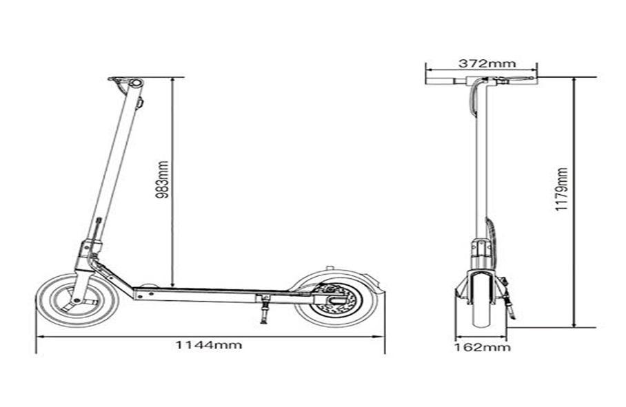
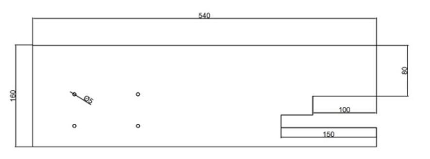
1) MS Base Plate: The MS base plate is made up of mild steel with the dimension of 540X160mm and the tickness of the plate is 6mm. this base plate is used as the overall body to withstand the weight of the air vessel, pneumatic cylinder & ourself. The upper body contains a two D-shaped plate to fix the handel bar, and the bottom of the plate contains a square shaped plate to fix the rear wheel. The over all body weight is 5.6kg.
ISSN: 2321-9653; IC Value: 45.98; SJ Impact Factor: 7.538
Volume 11 Issue II Feb 2023- Available at www.ijraset.com
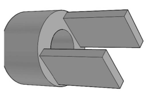
2) U-Shaped Shaft: The U-shaped shaft is used to connect the pneumatic cylinder & connecting rod, this shaft is made up of mild steel and the weight of the shaft is 450g. it has 3 drill holes, the first two holes is used to fix the connecting rod with the diameter of 9mm and the one large hole is used to fix the pneumatic with the diameter of 16mm.
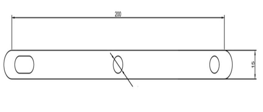
3) Connecting Rod: The connecting rod is to connect the pneumatic cylinder and wheel, this rod is used to convert the reciprocating motion into rotation motion. The power release from pneumatic cylinder is directly transferred to the wheel with the help of connecting rod. The length of the connecting rod is 200X10 with the 6mm thickness with the two drill holes to connect the wheel & pneumatic cylinder.
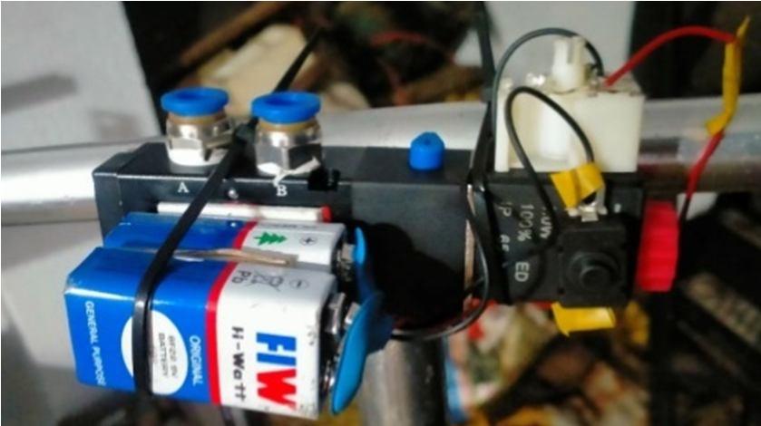
4) Electronic-Solenoid Valve: The Electronic-Solenoid Valve is used to circulate the compressed air in to pneumatic cylinder and to passed out into the atmosphere. This Electronic-Solenoid Valve is consist of a switch, battery, air circulating device. When all are attached the Electronic-Solenoid Valve is fixed in the handle bar to operate when we need.
5) Single Sliding Crank Mechanism: This mechanism is used to convert reciprocating motion into rotation motion. The pneumatic act as the piston which is in reciprocating motion and the connecting is helps to convert into rotation. It’s a simple mechanism which only we need a 3 main parts, the first is a piston and then connecting and finally the wheel. In this the length of the piston is equal to the radius of the wheel.
ISSN: 2321-9653; IC Value: 45.98; SJ Impact Factor: 7.538
Volume 11 Issue II Feb 2023- Available at www.ijraset.com
G. Calculation
Maximum pressure = 12 bar = 1200000 N/m2
Diameter of Pneumatic Cylinder = 40mm = 0.04m
Force (N)= Pressure (Nm2) × Area of Pneumatic cylinder
Area of Pneumatic cylinder = πr2/4
= π×(0.02)2/4
=3.1415×10⁻³ m 2
Force (N) = 1200000 × 3.1415 ×10-3
F= 376.99 Nm2 m= F/9.81 = 376.99/9.81 m=48.42 kg
III. RESULTS AND DISCUSSION
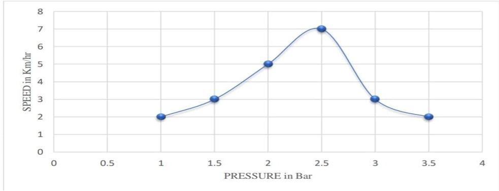
A skate scooter with pneumatic system is fixed and working with the electronic-solenoid valve. this skate scooter is working with the principle of single sliding mechanism. Each parts has been calculated and tested according to the producer given below. The every parts has been drawing using Autocad 3D modelling And assembled in the given exact area. Most of the parts are designed and made by using grinding and wielding of scrap metals, therefore the vehicle is pollution frees as well as reused product. When all the parts are assembled in the placed. The vehicle is tested by three different loads to estimate the range, time, power, speed & efficacy of the pneumatic pressure released by the cylinder. Each of the estimation is graphed and proved according to the given producer.
Fig.6 shows the power produce by pneumatic skate scooter for 55kg load. In this chart at 1 bar pressure the speed of the pneumatic skate scooter can be moved up to 2km/hr. at initial stage. As we can see that the speed is also increasing, at the 2.5 bar the power output is at maximum at which the speed of the pneumatic skate scooter produce its peak speed of about 7km/hr. which is not a high speed but if we increase the cylinder pressure we can increase the speed of the vehicle. At the end the speed is decrease and goes down to 2km/hr.
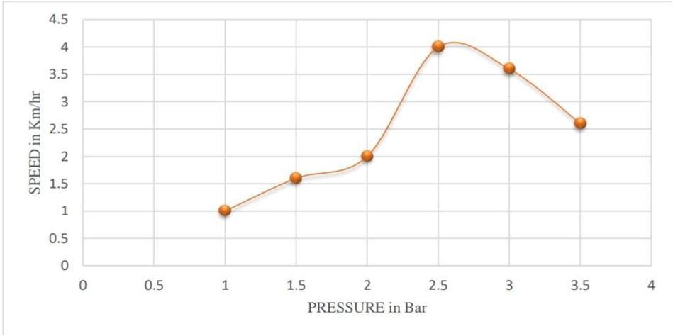
Fig.7 shows the power produce by pneumatic skate scooter for 65kg load.In this chart at 1 bar pressure the speed of the pneumatic skate scooter can be movedup to 1km/hr at initial stage. Due to the heavy weight compare to last result this has lower speed produce As we can see that the speed is also increasing, at the 2.5 bar thepower output is at maximum at which the speed of the pneumatic skate scooter produce its peak speed of about 4km/hr. which is not a high speed but if we increase the cylinder pressure we can increasethespeed ofthe vehicle. At theend the speed isdecrease and goes down to 3.5km/hr.