10 minute read
International Journal for Research in Applied Science & Engineering Technology (IJRASET)


ISSN: 2321-9653; IC Value: 45.98; SJ Impact Factor: 7.538
Advertisement
Volume 11 Issue II Feb 2023- Available at www.ijraset.com
4) Rectangular fin description:
Fin planform
Fin configuration
Rectangular
Rectangular fin
Number of fins 4
Tip chord 240 mm
Root chord. Cr 240 mm
Fin thickness, t 2 mm
5) Triangular fin description:
Fin planform Triangular
Fin configuration
Triangular fin
Number of fins 4
Root chord. Cr 240 mm
Fin thickness, t 2 mm
6) Swept fin description:
Fin planform Swept
Fin configuration Swept fin
Number of fins 4
Tip chord 120 mm
Root chord. Cr 120 mm
Fin thickness, t 2 mm
IV. COMPUTATIONAL FLUID DYNAMIC A. Methodology
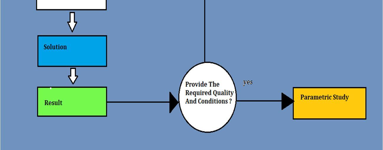
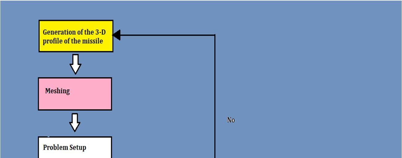
To meet specific requirements, each missile structure has a unique design. Due to the challenges of experimental testing, Computational Fluid Dynamics (CFD) is frequently utilized in the design process. In this study, a traditional CFD methodology was utilized to simplify the design process, which is depicted in Figure 3,
ISSN: 2321-9653; IC Value: 45.98; SJ Impact Factor: 7.538
Volume 11 Issue II Feb 2023- Available at www.ijraset.com
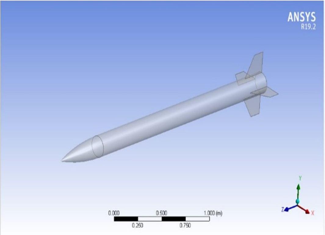
B. 3D Modelling
Using On-shape software, a 3D model of the missile was created based on dimensional specifications. The resulting model is displayed in Figure 4,
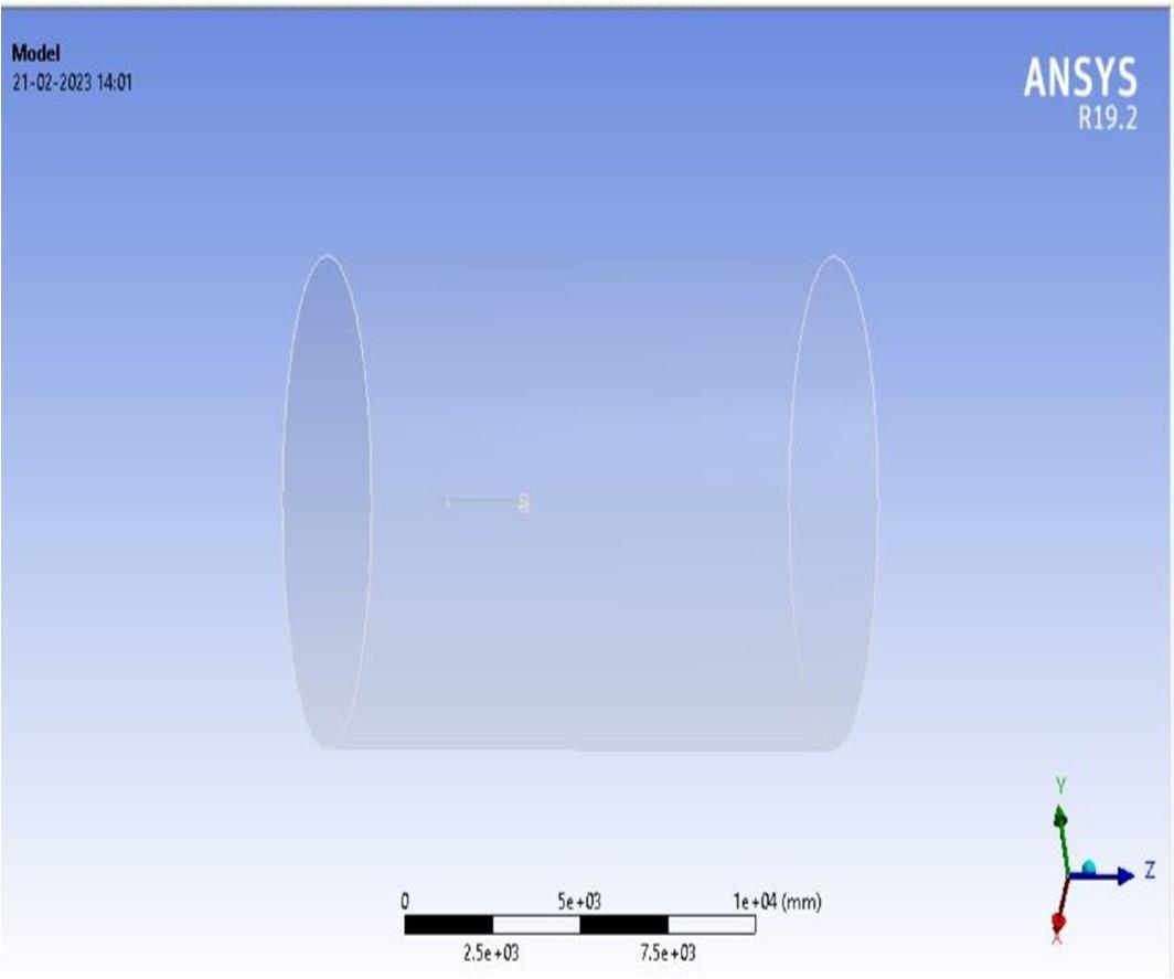
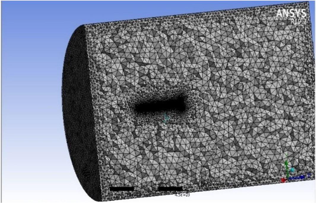
In the workbench, important steps were taken to assign the geometry, generate a mesh, and set up the simulation and results. The missile design was imported into the design modeller and enclosed with a cylindrical fluid domain, as shown in Figure 5,
This fluid domain was necessary for simulating air flow, and the inlet, wall, rocket, and outlet were assigned within the fluid domain. The inlet was the location where the air flow entered, and the outlet was the exit from the fluid domain. The wall acted as a control volume around the missile. The fluid domain had a Radius of 5 m and a length of 9 m.
C. Grid Generation
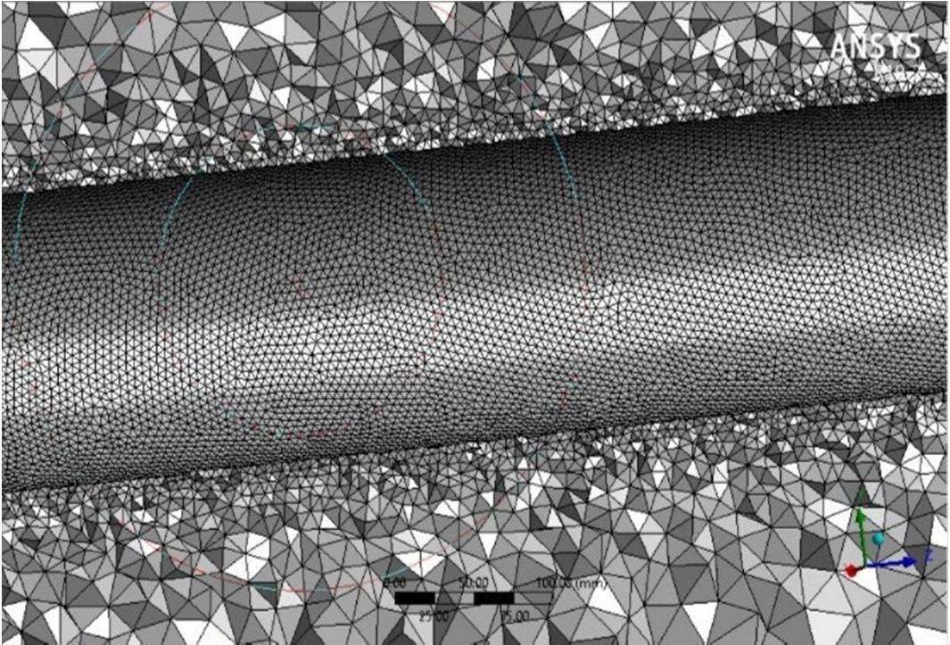
ANSYS Meshing was used to create a high-quality mesh after the Missile geometry was established. The quality of the mesh, which must precisely replicate the physical phenomena in the flow domain, has an impact on the numerical solution's precision and consistency. It is essential to pay close attention to the inlet and outlet regions as well as the boundary layer at the body's top. Since calculating drag force is required for this problem, the boundary layer needs a fine mesh structure. Figure 6 displays the grid structure that was generated.
ISSN: 2321-9653; IC Value: 45.98; SJ Impact Factor: 7.538
Volume 11 Issue II Feb 2023- Available at www.ijraset.com
The denser mesh structure surrounding the missile profile is shown in Figure 6, with decreasing mesh density as one moves towards the boundary of the domain. Inflation layers were used to construct this structure, with a first layer thickness of 0.0015 mm The thickness of the first layer in the inflation layer was kept small to ensure it is located close to the missile body for proper resolution of the boundary layer.
Finally, a study was conducted to check the independence of results from the mesh structure. The comparison was made based on the calculated drag force and the findings are presented in Table below,
Reducing the mesh size by 50%, from 4.8 million to 1.26 million, did not result in a difference greater than 1.7%. Therefore, it is more practical to use 1.26 million elements instead of 4.8 million elements to save computational time and resources.
D. Turbulence Model
Following mesh generation, the simulation's boundary conditions were set up. For this study, the k-omega SST viscous model was selected, which is a two-equation eddy-viscosity model. This model uses the shear stress transport (SST) formulation to combine the best features of k-omega and k-epsilon models, resulting in a more accurate and stable solution. The k-omega formulation is used in the inner boundary layer, allowing the model to be directly usable down to the wall without additional damping functions. In freestream regions, the SST formulation switches to k-epsilon behaviour, avoiding responsive to inlet free-stream turbulence characteristics. While the SST k-omega model does produce larger turbulence levels in regions with normal strain, this is less pronounced than in the normal k-epsilon model. Overall, the SST k-omega model was used in the study due to its good behaviour in adverse pressure gradients and separating airflow.
E. Simulation
The problem was set up using (ANSYS Fluent) and simulated using ANSYS Fluent Solver. The boundary conditions were defined using regions.
In ANSYS fluent-Pre, the inlet and outlet locations were designated as "Inlet" and "Outlet" boundary types, respectively. The inlet boundary was defined with a normal speed of 170 m/s to 850 m/s (0.5 Mach to 2.5 Mach), and the outlet boundary was defined with a static pressure of 0 Pa. The reference pressure is selected as 1 atm. The missile was defined as a non-slip wall, and the remaining regions were defined as symmetry. The fluid used was air, modelled as an ideal gas, and the k-omega SST turbulence model was employed. A residual target of 10^-6 was set, and a monitor point was used to check velocity convergence in the middle section. The problem was solved using steady-state conditions in ANSYS fluent Solver Manager. Results are presented in Section 5.
ISSN: 2321-9653; IC Value: 45.98; SJ Impact Factor: 7.538
Volume 11 Issue II Feb 2023- Available at www.ijraset.com
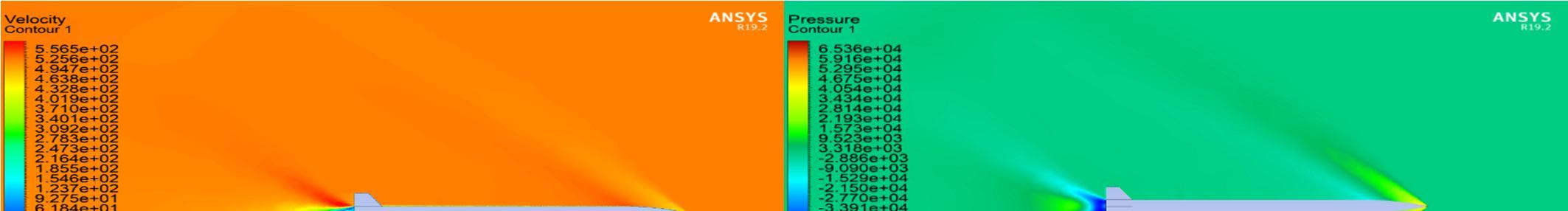
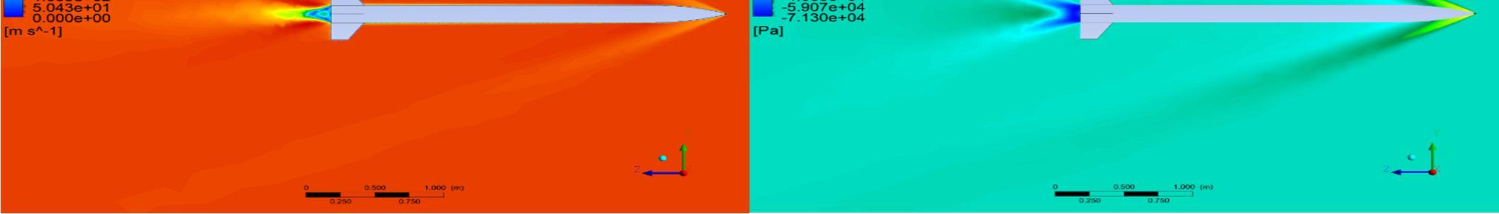
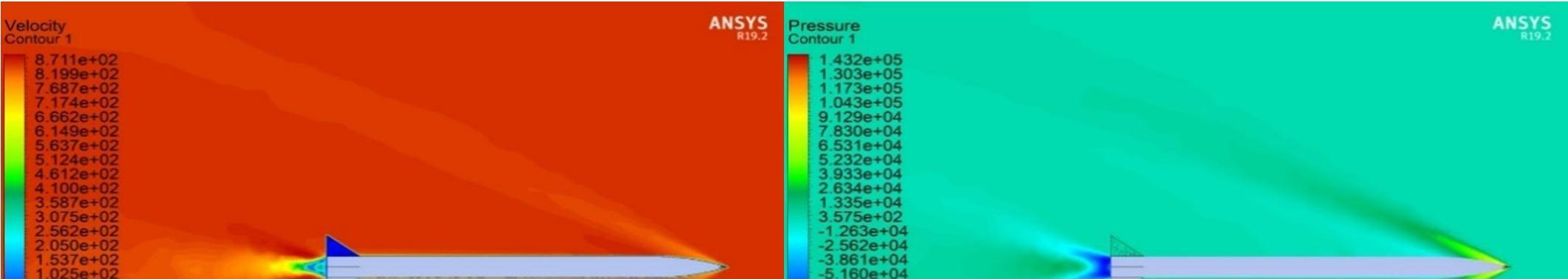
V. RESULTS
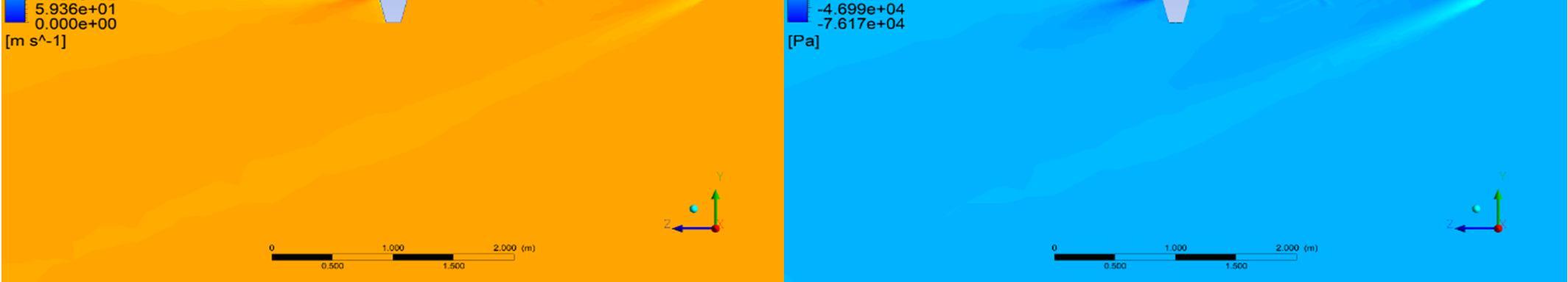
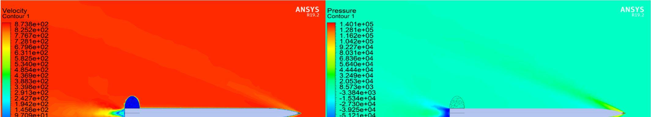
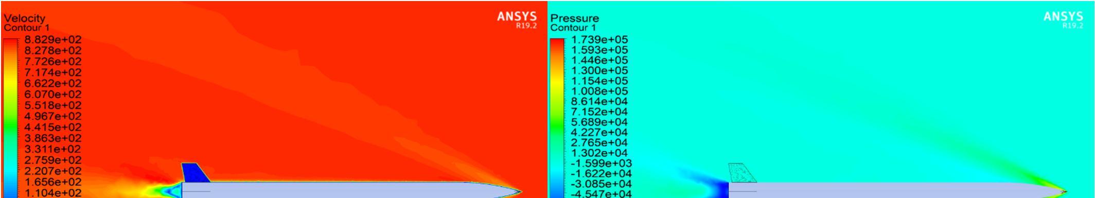
At Mach 0.5, the flow around the missile appears to be relatively smooth with no significant shock waves visible. This is because the missile is flying at a relatively low speed and the air particles can flow around the missile smoothly.
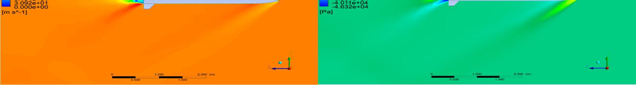
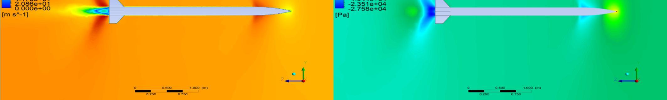
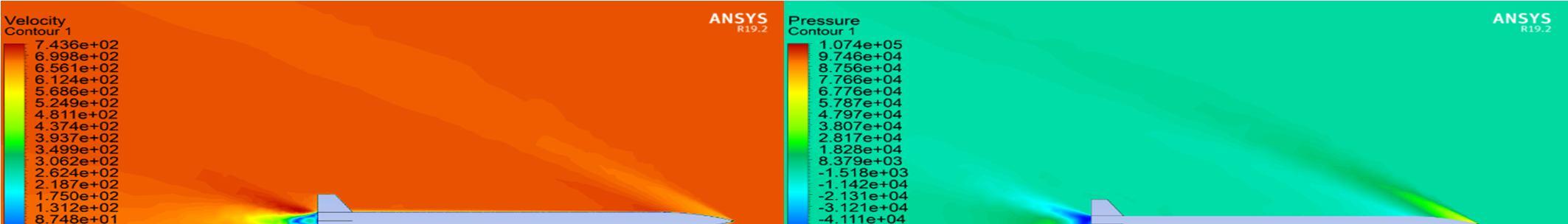
At Mach 1, the shock wave has just begun to form at the nose of the missile. This is because the missile is now flying at the speed of sound, and as the air particles approach the nose of the missile, they begin to compress and slow down, resulting in the formation of a shock wave (Normal).
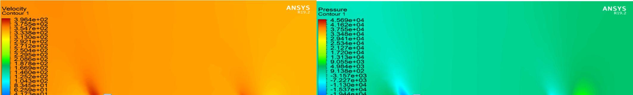
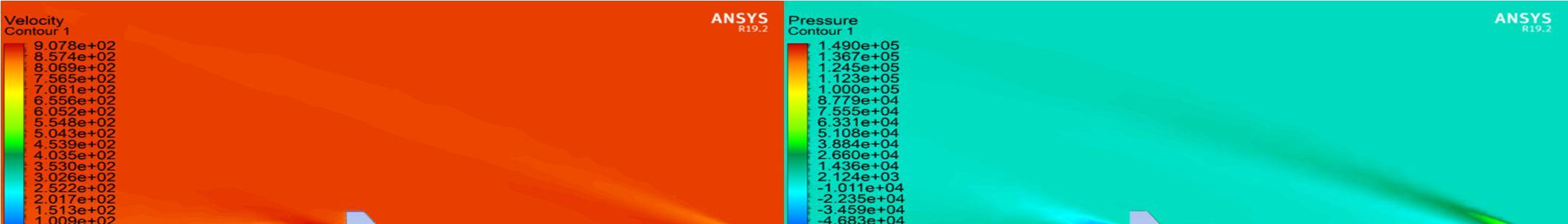
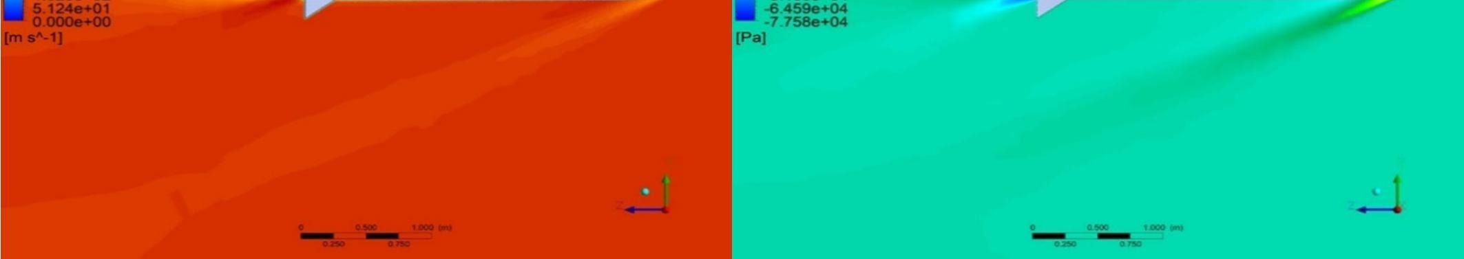
At Mach 1.5, the shock wave has become more prominent and now extends farther back along the missile. This is because the missile is now flying at supersonic speeds, and the air particles are rapidly compressed and slowed down as they approach the nose, resulting in a strong shock wave.
ISSN: 2321-9653; IC Value: 45.98; SJ Impact Factor: 7.538
Volume 11 Issue II Feb 2023- Available at www.ijraset.com
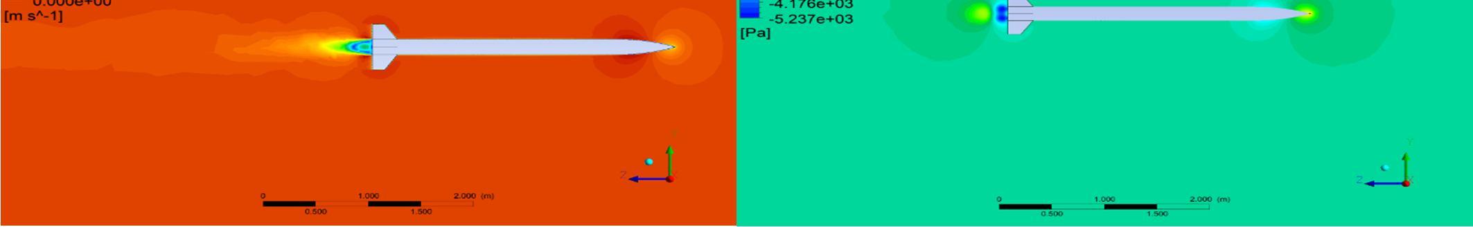
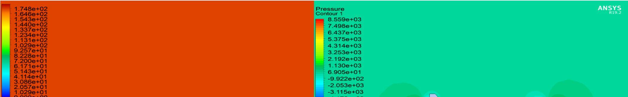
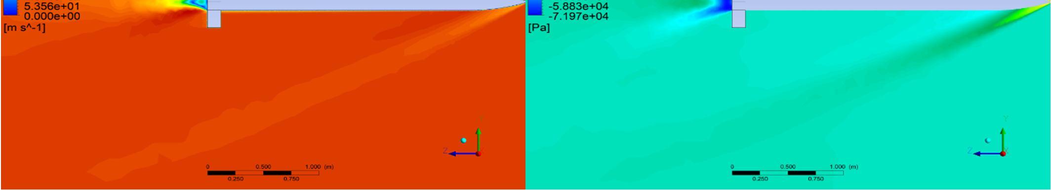
At Mach 2, the shock wave has now fully formed and extends all the way back to the tail of the missile. This is because the missile is now flying at a higher supersonic speed, and the air particles are compressed even more rapidly as they approach the nose, resulting in a stronger and more extended shock wave.
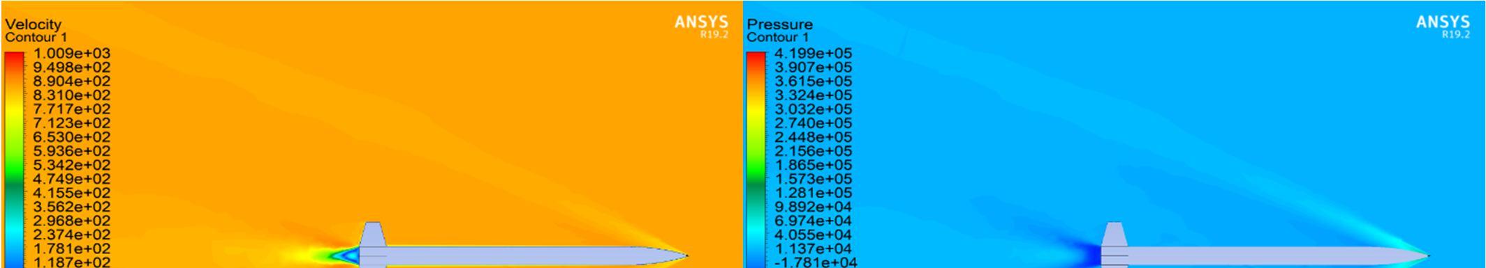
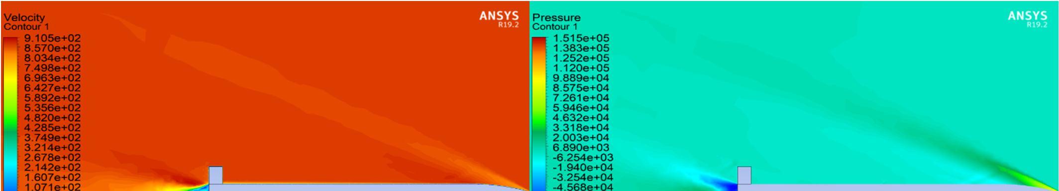
At Mach 2.5, the shock wave appears to be like that at Mach 2, but with a more noticeable oblique shock wave forming ahead of the missile. This is because the missile is now flying at even higher supersonic speeds, and the air particles are compressed even more rapidly, resulting in the formation of an Oblique shock wave ahead of the missile, in addition to the strong shock wave along its body.
International Journal for Research in Applied Science & Engineering Technology (IJRASET)
ISSN: 2321-9653; IC Value: 45.98; SJ Impact Factor: 7.538
Volume 11 Issue II Feb 2023- Available at www.ijraset.com
ISSN: 2321-9653; IC Value: 45.98; SJ Impact Factor: 7.538
Volume 11 Issue II Feb 2023- Available at www.ijraset.com
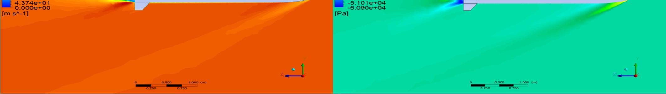
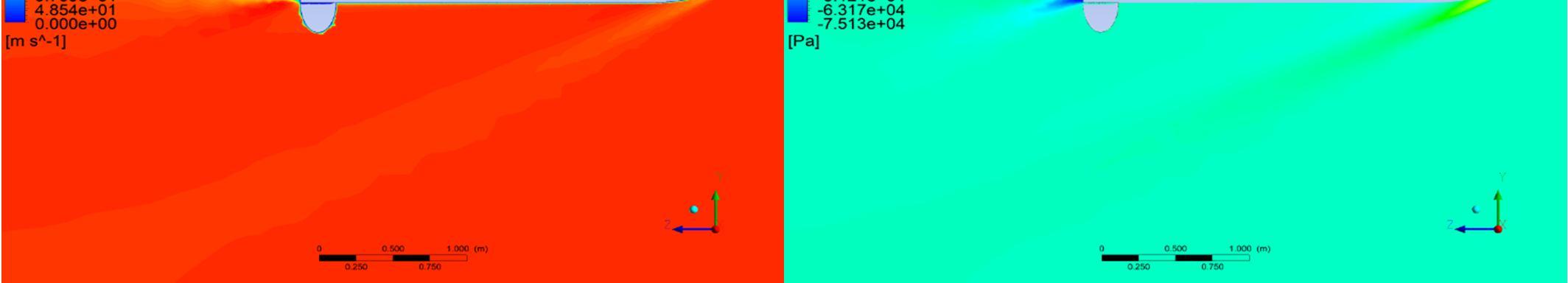
When a missile is at zero angle of attack, the airflow around it is symmetrical and a bow shock wave forms at its nose. The strength of this shock wave increases as the Mach number increases, along with the wave drag. At Mach numbers higher than one, oblique shock waves are formed at the leading edge of the fins, intersecting with the bow shock wave to create an area of increased pressure and drag behind the fins known as the shock wave interference region. This region is more pronounced at higher Mach numbers and is influenced by the shape and size of the fins.
At Mach 0.5, the airflow disturbance is minimal, and its effect on the missile is weak, but as the Mach number increases, the airflow compression becomes more intense, leading to increased drag.
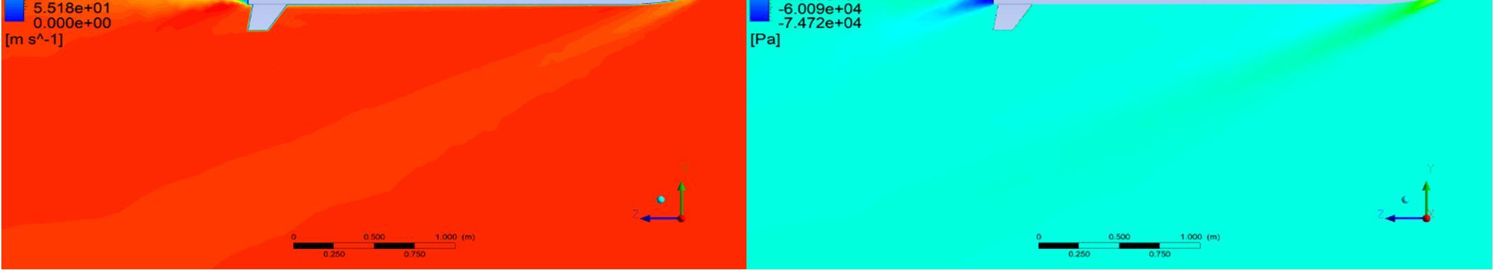
At Mach 1, a strong bow shock wave is formed near the nose of the missile, increasing air pressure and temperature behind it.
At Mach 1.5 and above, the oblique shock waves merge to form a strong bow shock wave at the nose of the missile, resulting in a significant increase in drag due to the high-pressure region in front of the missile. Shock waves are formed due to the compressibility effects of the airflow, leading to deceleration and increased air pressure behind them.
0
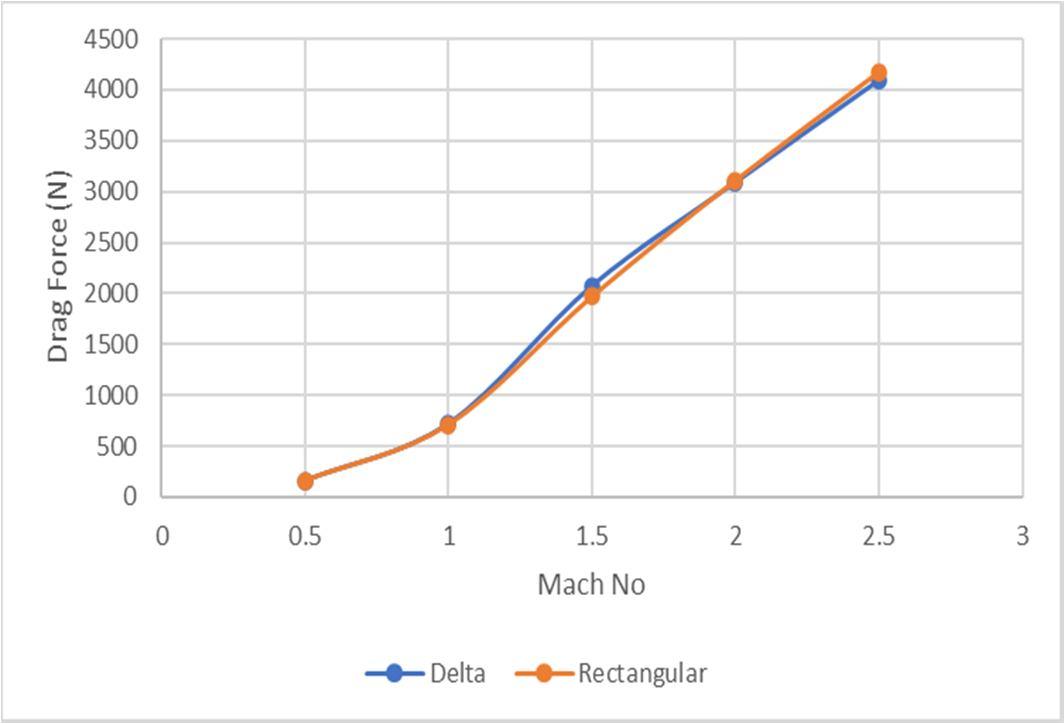
We observe rectangular fin shapes have less drag at subsonic speed 0.5 Mach as compared to other fin shapes because they have a lower aspect ratio compared to other fin shapes, swept-back fins
ISSN: 2321-9653; IC Value: 45.98; SJ Impact Factor: 7.538
Volume 11 Issue II Feb 2023- Available at www.ijraset.com
A lower aspect ratio results in a shorter chord length and broader span, which reduces the size of the wingtip vortices that are generated at the tips of the fins. These vortices are a major contributor to drag at subsonic speeds, as they create turbulence in the airflow around the fins, which increases drag. Furthermore, rectangular fins are less prone to stall at lower angles of attack compared to other fin shapes, which also contributes to their lower drag. At low angles of attack, rectangular fins can produce lift with minimal drag, making them efficient for subsonic flight.
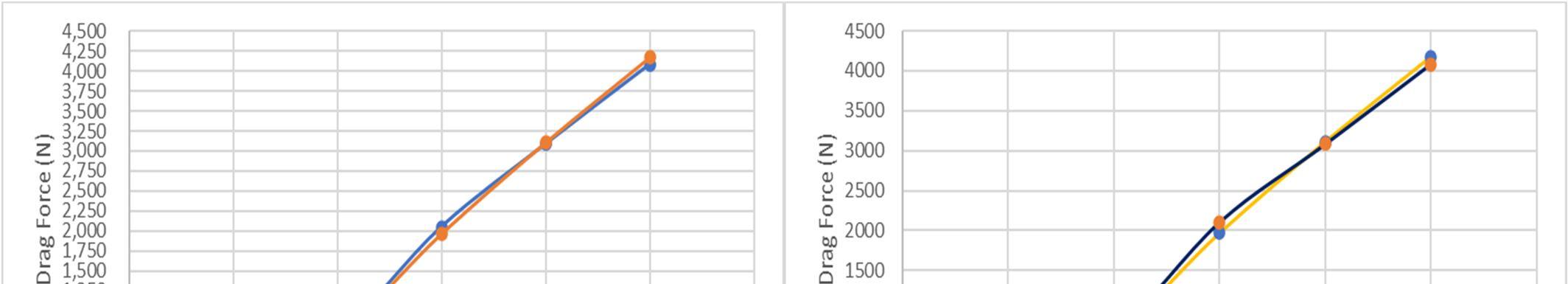
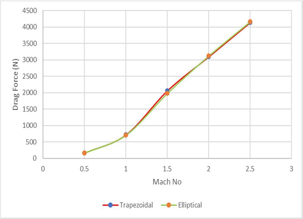
2) Transonic
Figure 28 show the results For Trapezoidal and Elliptical fin Shape. The simulations were conducted at M = 0.5,1,1.5,2, And 2.5 and at angles of attack 00 .
In the transonic regime, elliptical Fin shape tend to have less drag compared to fins with another Fin shape. This is because the airflow around the fin can reach supersonic speeds near the tips of the fins, creating shockwaves and increasing drag. Fins with rounded shape help to minimize the formation of these shockwaves and reduce drag in the transonic regime
3) Supersonic
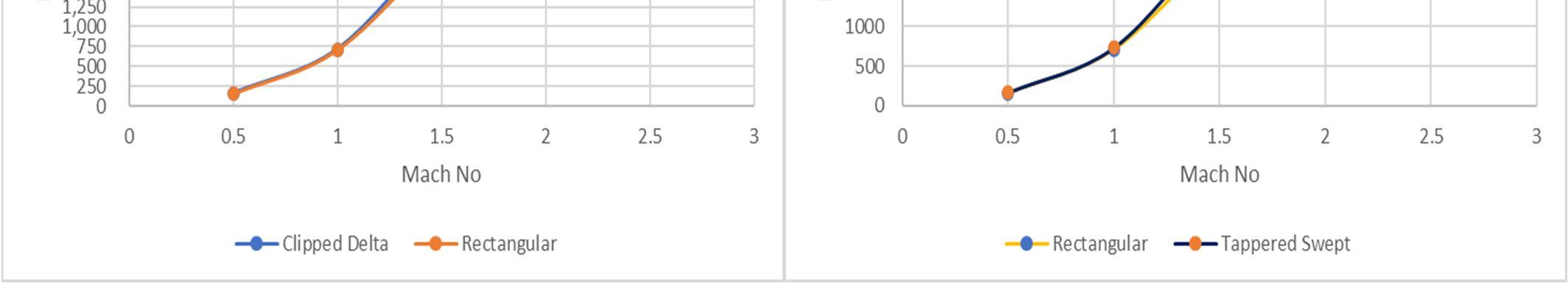
Figures 29 and 30 show the results For Clipped Delta, Tapered Swept and Rectangular fin Shape. The simulations were conducted at M = 0.5,1,1.5,2, And 2.5 and at angles of attack 00 .
ISSN: 2321-9653; IC Value: 45.98; SJ Impact Factor: 7.538
Volume 11 Issue II Feb 2023- Available at www.ijraset.com
We observe Clipped Delta and taper swept fin shapes have less drag at supersonic speed at 2.5 Mach, because they are designed to minimize the formation of shock waves, which are a significant source of drag at these speeds.
At supersonic speeds, shock waves are generated when the airflow over the surface of the fin is disrupted by the sudden increase in air pressure. These shock waves cause a significant increase in drag.
Delta and tapered swept fins are reduce the strength and number of these shock waves by gradually redirecting the airflow around the fin. The sharp leading edge of the Clipped delta fin and the tapering of the swept fin help to reduce the pressure gradient, minimizing the formation of shock waves and reducing drag.
VI. CONCLUSION
In conclusion, the study of the flow characteristics around a missile (fins) at different Mach numbers has revealed the formation of shock waves due to the compressibility effects of the airflow. The intensity and size of these shock waves vary with the Mach number and the shape and size of the fins. The rectangular fin shape has been observed to have lower drag at subsonic speeds due to its lower aspect ratio and reduced wingtip vortices. The elliptical fin shape has been found to be more efficient in the transonic regime due to the minimization of shock wave formation. Finally, the Clipped Delta and taper swept fin shapes have been found to be effective in reducing shock wave formation and drag at supersonic speeds. The findings of this research are important in the design and development of missiles and other high-speed Rocket. Understanding the flow characteristics and the factors that influence drag can help in the development of more efficient and effective designs. Future research can explore further the impact of fin shape and size on the aerodynamic characteristics of missiles and other highspeed vehicles.
References
[1] Ukirde, Kishorkumar, and Shyam Rathod. "Aerodynamic Analysis of Various Nose Cone Geometries for Rocket Launch Vehicle at Different Mach Regimes." AIP Conference Proceedings. Vol. 2421. No. 1. AIP Publishing LLC, 2022
[2] Deepthi Mol S.S. "Numerical Study on Drag Reduction for Grid Fin Configurations." AIAA Modeling and Simulation Technologies Conference, January 2014. doi: 10.2514/6.2014-0519
[3] Aytaç Z. and Aktaş F., “Utilization of CFD for the aerodynamic analysis of a subsonic rocket”, Politeknik Dergisi, 23(3): 879-887, (2020). DOI: 10.2339/politeknik.711003
[4] Belega, B. A. (2015). Analysis of New Aerodynamic Design of the Nose Cone Section Using CFD and SPH. 3rd International Workshop on Numerical Modelling in Aerospace Sciences, NMAS 2015. DOI: 10.13111/2066-8201.2015.7.2.4
[5] Mawhood, P., Kontis, K., & Matejka, T. (2019). Optimizing supersonic missile fin design using computational fluid dynamics. Journal of Defense Modeling and Simulation: Applications, Methodology, Technology, 16(1), 89-102. doi: 10.1177/1548512918821566
[6] Watkins, W. S., Cook, T. W., & Uyehara, O. A. (1983). Wind tunnel and trajectory simulations of missile stability and control. Journal of Aircraft, 20(9), 766772. doi: 10.2514/3.45390
[7] Munson, J. E., & Miller, R. L. (1965). Fin shapes for subsonic and supersonic missiles. Journal of Aircraft, 2(2), 107-113. DOI: 10.2514/3.2768
[8] Moran, K. J., & Beran, P. J. (1997). Simulation of high Mach number missile configurations. In 12th AIAA Computational Fluid Dynamics Conference (p. 2715)
[9] DeSpirito, J., Kandil, O. A., & Shang, J. S. (2002). Aerodynamic analysis of a generic canard-controlled missile configuration. Journal of Spacecraft and Rockets, 39(6), 859-867. DOI: 10.2514/2.3885
[10] Gulay, E., Gocmen, T., & Yildiz, F. (2011). Experimental and numerical investigations of wrap-around fins for missile configurations. Journal of Aerospace Engineering, 24(4), 480-492. doi: 10.1061/(ASCE)AS.1943-5525.0000094
[11] Sharma, N., & Kumar, R. (2017). Aerodynamic behaviour of a single planar fin of semi-circular missile model at subsonic to supersonic speeds. Journal of Mechanical Science and Technology, 31(6), 2913-2922. doi: 10.1007/s12206-017-0543-4
[12] Nizam BIN Dahalan and Iskandar Shah Ishak. "Aerodynamic Characteristics of a Curved Fin Rocket." Journal of Advanced Research in Fluid Mechanics and Thermal Sciences 41, no. 1 (2017): 45-54
[13] Pektaş, M., & Ejder, E. (2019). Experimental investigation of the effects of different fin shapes on apogee and stability of model rockets. Aerospace Science and Technology, 91, 399-405. doi: 10.1016/j.ast.2019.05.026
[14] Sumanth, N. (2022). CFD analysis of missile with trapezoidal and planar fins. International Journal of Mechanical and Production Engineering Research and Development, 12(1), 1-10
[15] Chin, S. S. (2001). Missile configuration design. American Institute of Aeronautics and Astronautics
