22 minute read
A wireless bionic soft robotic fish using shape-memory alloy actuators

from IAES International Journal of Robotics and Automation (IJRA) Volume 11, Issue 4, Dec. 2022
by IJRA

Kewei Ning1, Hideyuki Sawada2
1Department of Applied Physics, Graduate School of Advanced Science and Engineering, Waseda University, Tokyo, Japan
Advertisement
2Faculty of Science and Engineering, Waseda University, Tokyo, Japan
Article Info
Article history:
Received Jan 14, 2022
Revised Aug 28, 2022
Accepted Sep 20, 2022
Keywords:
Bionic fish robot
Shape memory alloy wires
Soft actuator
Soft robotics
Swimming control
Abstract
In this study, we present the construction of a wireless bionic soft robotic fish that has a silicone tail and uses shape-memory alloys (SMAs) as actuators. Even though there have been a lot of recent advancements in the field of soft robotics, the use of SMAs as actuators for soft robots is still not something that is investigated very often. In the course of this research, we plan to work toward the creation of a realistic bionic fish robot that possesses a high level of mobility in the water, in addition to being light enough, strong enough, and flexible enough. The purpose of this study is to expound on the process of optimizing the morphologies of the fish body, as well as the optimization of the electromechanical behavior of the SMAs, in order to generate swimming motions in the fish. Our attention will be on the optimization of these two aspects. This report also outlines some preliminary but promising physical tests that were conducted to create a robotic fish with the similar shape.
This is an open access article under the CC BY-SA license.
Corresponding Author:
Kewei Ning
Graduate School of Advanced Science and Engineering, Waseda University
Tokyo, Japan
Email: ningkewei1096@akane.waseda.jp
1. INTRODUCTION
Recent years have seen a surge in activity in the field of robotics research, which has led to the birth of several fascinating new concepts. Soft robots are made out of soft materials and are driven by electrically activated materials. Soft robots are typically inspired by the form of biological organisms. Soft robots have a number of benefits over traditional robots, including a risk-free connection between humans and machines, the capability of being implemented in wearable devices, and the capacity to manipulate objects in a straightforward yet adaptable manner [1]. Soft robots now in existence may be loosely classified into two distinct functional categories: motor robots, which have the ability to creep, crawl, and swim, and manipulator robots, which have the ability to grip items [2]. Saito et al. [3] produced a soft micromachine claw that can grab items with a mass that is up to 3 mg by utilizing a photosensitive ionic adhesive in his creation. Hara et al. [4] created a molecular robot that is capable of self-oscillation and is powered by the Belousov-Zhabotinsky reaction. Katzschmann et al. [5] demonstrated a soft-bodied, hydraulically-powered, autonomous robotic fish that was capable of continuous swimming in three dimensions. The root-like, steerable soft robot created by Naclerio et al. [6] is capable of controlling the lift and drag forces that occur underground, allowing it to dig through actual sand.
A wide range of soft robots have been fabricated by researchers making use of smart materials as actuators. Actuators for soft robots have been created using shape memory alloys (SMAs) [7]–[9], pneumatic artificial muscles (PAMs) [10]–[12], fluidic elastomer actuators (FEAs) [13]–[17], and ionic polymer-metal composites (IPMCs) [18]–[20]. Because of their quick reaction time, great deformability, and high-frequency
Journal homepage: http://ijra.iaescore.com response [21], we believe that SMA wires are the appropriate material for use in the actuators of robots. In addition, since SMAs have a low driving voltage and a low energy consumption, it is possible to include a smaller battery into the robot due to these characteristics. SMA wires have been utilized by researchers so far in order to develop a wide variety of soft robots. An SMA-driven soft robot with three different motion modes was invented by Du et al. [22]. These modes include rolling, omega crawling, and vermiculation. Meshworm is a robot that was created by Seok et al. [23] that is designed to mimic the writhing movement of earthworms. It is operated by enclosing polymeric tubes with a grid of SMA wires. A significant amount of research has been put into the development of SMA-driven soft-bodied robotic fish. Wang et al. [24], [25] introduced a flexible biomimetic microrobot fish that was driven by its fins and had distinct SMA actuators. We created a swim motion simulator using a flexible silicone tail equipped with a straightforward SMA actuator mechanism and tested it at a number of different frequency levels [26]. We develop a concept for the construction of bionic fish based on natural fish, in which body and/or tail fin (BCF) propulsion and median and/or paired fin (MPF) propulsion are the two fundamental mechanisms for fish to swim in nature [27]. The BCF propulsion mode is straightforward and easy to understand, and it has the potential to deliver effective movement at increased speeds and acceleration rates [28]. On the basis of earlier research, we make an attempt to construct fish robots in order to explore the controllability of SMA wires when used as actuators for BCF propulsion.
In this study, we describe a bionic soft robotic fish that has a SMA fishtail and a very straightforward construction. The major purpose is to do an analysis of the electromechanical properties of SMA actuators that have a straightforward construction. The secondary goal is to find a solution to the problem of the offset in swimming trajectory that is caused by the imbalanced swing of the fishtail. We feel that our analysis, which is based on physical tests, gives fresh insights into SMA actuators and is valuable for future research in the field of soft robotics.
2. METHOD
2.1. Shape memory alloys and their characteristics
In recent years, shape memory alloys (SMAs), which are also known as form-memory alloys, have garnered a lot of attention as useful materials. They are being utilized in a variety of applications, including couplings, actuators, medical guide wires, and others, and they are potential candidates for enlarging the existing collections of smart materials [29]. Actuators for our bionic robotic fish are made out of BioMetal fiber (BMF) series SMA wires from BioMetal®, which we employ in our study. Due to the BMF’s solid internal structure, it is long-lasting and possesses operational properties that are consistent throughout time. The fact that it is relatively thin while yet being able to generate a significant amount of force makes it appropriate for use in microactuators.
Table 1 displays the parameters of the BMF75 that we utilized in our research. When an appropriate voltage is supplied to a SMA wire, the temperature of the wire rises, and the wire begins to compress at a temperature of roughly 70 degrees Celsius. The greatest possible shortening accounts for more than 5% of its whole length. After being de-energized, it immediately returns to its natural length and temperature, which is below 70 degrees Celsius. Because of this ability, we are able to cause the wire to contract, and at the same time, the wire may cause the tail made of silicone to bend in a certain way, which enables the fish to swim. Here, we report on our attempt to construct a robotic fish and optimize the designs of a bionic soft robotic fish by introducing two types of robotic fish.
2.2. Design and construction of the robot shell
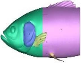
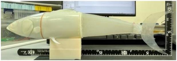
As can be seen in Figure 1(a), the form of the bionic robot was derived from a scanned three-dimensional model of an actual fish [30], namely a regular salmon. Because biological fish are often
A wireless bionic soft robotic fish using shape-memory alloy actuators (Kewei Ning) rather tiny, the robot’s dimensions had to be increased by a factor of 3.125, taking them 14.5×21.2×88 mm (W×H×D) to 45.5×66.7×277 mm (W×H×D). After cutting off the fish’s tail and leaving only the head and body, the fish’s total measurements were 45.4, 66.2, and 149 mm, and its mass was calculated to be 52 grams. We had to cut off the model’s tail in order to make the shell accommodate the silicone extension. The remaining body may be broken down into two sections: the front and the back. In order to create a mortise and tenon joint linking structure, the thickness of both pieces must be reduced from the interior to a shell thickness of three millimeters. In order to facilitate reassembly, each of the model’s fins has been dismantled individually, and the construction of the model uses mortise and tenon joints. The 3D mold of the fish shell is shown in Figures 1(a) and (b), and the printed shell is shown in Figure 1(c).
Figure 1. A scanned 3D model of a genuine fish, including (a) a salmon 3D model, (b) a model of the fish shell as a 3D scan, and (c) a printed version of the shell
2.3. Structure and construction of the silicone tail actuator
The manufacturing of a silicone tail is the most complicated and vital issue because, after realigning the body/caudal fin (BCF) propulsion mode, the propulsion force is created by the tail activities. This implies that the fabrication of a silicone tail is the most important issue. In the prior research that we conducted [28], SMA wires were embedded into both sides of each of the elastomer material’s two faces. The size of the fish and the amount of mass it contained both increased as the robotic fish evolved. Due to the fact that the larger fish body demands a larger tail, two sets of SMA wires will not be adequate to drive the increased tail. Following the findings of our investigation, we revised the overall layout of the tail.
In the tail are installed a total of four SMA wires, two for each side. Figure 2 provides an illustration of the construction of the silicone tail. On side A are two wires colored red, and on side B are two wires colored black, as shown in Figure 2(a) Figure 2(b) show side A has two wires colored red, and side B has two wires colored black. This study made use of the silicone gel known as Dragon Skin™ 10 MEDIUM, which was manufactured by Smooth-On. According to the findings of our earlier research [28], the shape of the tail fin, which is intended to improve the animal’s propulsion in the water, is shaped like a crescent. The fin is fashioned from a sheet of transparent ABS material that is 2 mm in thickness.
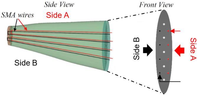
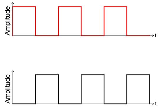
A simple enlargement makes the tail structure too heavy. Hence, we reduce the amount of silicone rubber by narrowing the width of the tail. With a tail length of 110 mm, an approximately 230 mm long SMA wire is used. We then calculate that the necessary driving voltage is approximately 16.5 volts. Side A and Side B are supplied with alternating square wave pulse currents, which are shown in Figure 2(c). By giving alternating pulse currents, the fishtail makes swimming motions left and right alternatively.
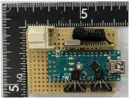
2.4. Microcontroller unit and battery
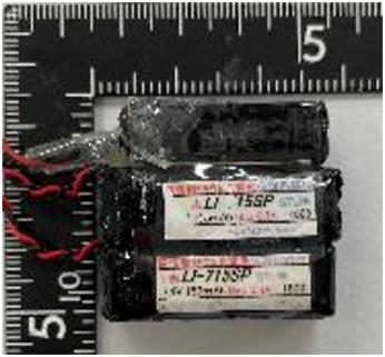
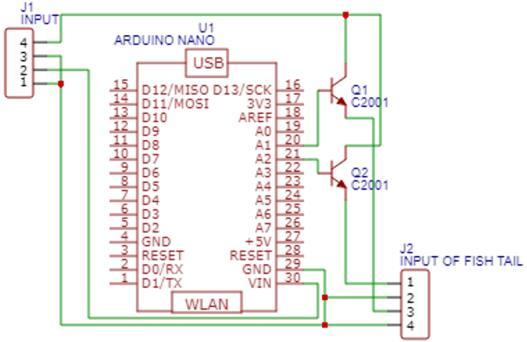
An Arduino Nano is used as the MCU, and a 433 MHz RF transmitter with a receiver kit is used for wireless communication, which is shown in Figure 3(a). An Arduino UNO is used to build a remote controller for the robot. Three small Li batteries with sizes of 45×10×39 mm are used for the power supply, as shown in Figure 3(b). In actual use, a full charge provides 7.8 to 8.4 volts per battery. Two batteries connected in series can provide 15.6 to 16.8 volts of power for powering the tail, which is enough to drive the SMA wires. The left battery is used for powering the MCU. Because the Arduino Nano allows an input voltage of 7 to 12 volts, we chose to power the tail and the controller separately. Additionally, three batteries work as a counterweight for the robot fish.
2.5. Assembly of the bionic soft robotic fish
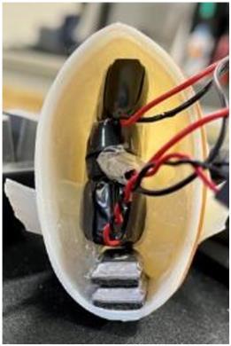
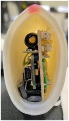
The following steps make up the assembly procedure for the robotic fish. Strong glue was used to adhere the fish body and fish tail together, and then silicone glue was used to seal the joint and make it watertight. As can be seen in Figure 4(a), the only components found within the body of the fish are the controller and the counterweight block. As can be seen in Figure 4(b), the batteries and the counterweight block are housed within the head of the fish. Figure 4(c) depicts the finished product of the robotic soft fish assembly.
2.6. Control of fin flipping motion
According to the information provided before, the four SMA wires in the fishtail are split evenly between the left and right sides. The micro control unit (MCU) is responsible for regulating the voltage at the triode’s base, which in turn determines whether or not the fishtail current is allowed to flow. The two different sets of SMA wires receive electricity in alternating fashion. The current that is regulated by the PMW can be seen in Figure 5(a), and the circuit that the MCU uses can be seen in Figure 5(b). The MCU is composed of two primary components: the Arduino Nano IoT 33, which acts as a controller, and the triode C2001, which acts as a switch. Both of these components are known collectively as the MCU. A connection has been made between the A1 and A2 ports of the controller and the base of the triode. The output of ports A1 and A2 is either high (more than 0 volts) or low (5 volts). When the output of A1, A2 is low, the triode enters the as-of zone. This means that the collector and emitter are not conducting, and the diastolic condition of the fishtail SMA wires is not activated. The collector and emitter of the triode are conducting when the output of A1 and A2 is high. Additionally, the fishtail SMA wire is activated and constricted when this occurs, which causes the fishtail to bend.
The ratio of the amount of time that the fishtail swings to the left to the entire amount of time that each operational cycle lasts is what we mean when we talk about the flipping duty cycle, abbreviated as D. PW refers to the amount of time that passes during one motion cycle during the left fishtail swing. The letter T denotes the duration of a motion cycle. For instance, the period of a motion cycle T is 500 milliseconds when the duration of the left fishtail swing in one motion cycle PW is 250 milliseconds. The flipping duty cycle D is equal to fifty percent when these conditions are met.
Figure 5. PMW controlled current and MCU circuit (a) PMW controlled current for driving SMA wires and (b) circuit diagram of MCU

3. RESULTS AND DISCUSSION
3.1. Experimental setup
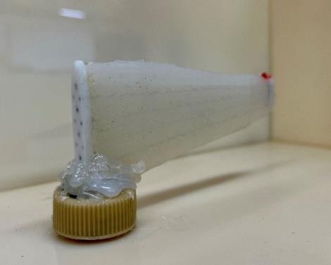
Experiments are carried out to determine the fish’s swimming performance in the water as well as their capacity to do the fishtail swing. In the initial stage of the tail swinging experiment, a jig is constructed with the intention of holding the tail root. To open a bottle cap, a triangle-shaped aperture must be cut into it. The root of the tail is fastened to the triangular hole, and slow-motion photographs taken with a video camera at 240 frames per second are used to record the swinging motion of the tail. For the purpose of analysis, the movies that were collected are imported into Kinovea, which is a free and open-source video player specialized in sports analysis. Figure 6 depicts the testing platform in its entirety. In the second experiment, a swimming pool with dimensions of 1500×600×2200 mm (W×H×D) filled with water 55 cm deep is prepared. A camera set on a tripod is placed at a height of 170 cm and captures the swimming behavior, as shown in Figure 7. The fish is quietly placed in the water, and it stays at a depth of 3 cm from the water’s surface. By sending the starting signal to the fish through infrared communication, the fish starts swimming, and the swimming behavior is recorded by a camera with a 4K resolution at 30 frames per second. The captured videos are loaded into Kinovea in order to do analysis on them. We put up positioning points across the experimental site in order for the analysis program to detect the size of the experimental site. This allows us to obtain more precise readings when measuring the speed of the fish.
3.2. Experiment for silicone tail swing amplitude test
As part of this experiment, both the status of the tail movement and the swing amplitude will be investigated. The driving voltages for the fishtails are equal to 14.8 volts. During the test, the waveform that is delivered to the fishtail is a square wave with a duty cycle of 50%. The waveforms that are supplied to the two sides are in opposing phases, which enables the fishtail to swing to the left and right, reciprocally.
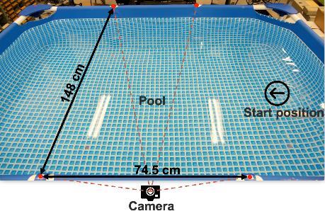
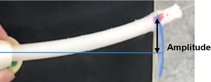
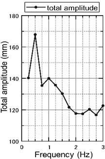
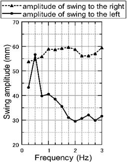
Figure 8 provides a visual representation of the definition of the amplitude of the tail swing. Figure 9 depicts a graph showing the amplitude of the tail swing as a function of time at a frequency of 2 Hz. In addition, the fishtails greatest amplitude while swinging to the left and right was distinct from one another. After two seconds had passed, the highest amplitude of the swing to the right got stable at about 58 mm, whereas the maximum amplitude of the swing to the left became stabilized at approximately 24 mm. When compared to the amplitude of the left swing, the right swing has an amplitude that is roughly 34 mm larger. Figure 10(s) represents of the maximum tail swing amplitudes at various swing frequencies for both sides. The amplitude of the swing to the right is shown by the red line, while the amplitude of the swing to the left is represented by the green line. Figure 10(b) represents the overall tail swing amplitude at a variety of various frequencies.
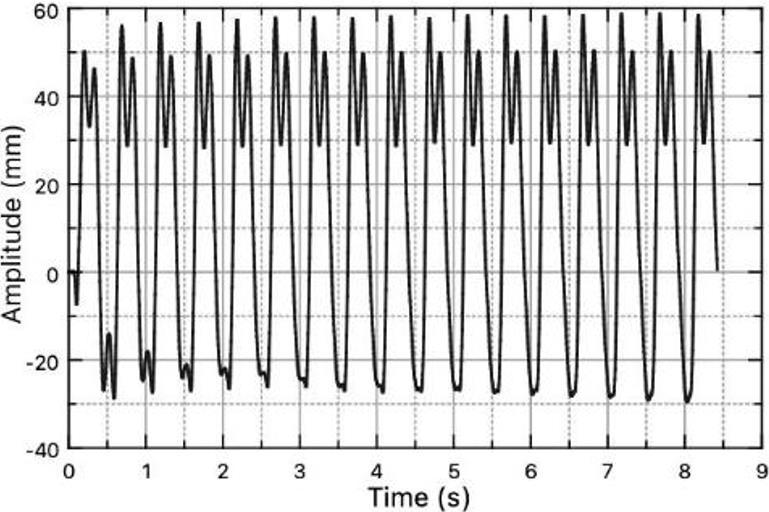
From the maximum tail swing amplitudes at different swing frequencies on both sides, we can find that the rightward swing’s maximum amplitude stabilized around 54 mm to 60 mm. The leftward swing’s maximum amplitude is, however, not stable as the rightward. Except for a peak at 0.5 Hz, the overall oscillation decreases with increasing frequency. The leftward swing amplitude stabilizes at about 30 mm after 1.75 Hz. Due to the problem of the leftward swing, the total tail swing amplitudes on both sides maintain a consistent pattern with the leftward swing amplitude. The total tail swing amplitudes on both sides also have a peak at 0.5 Hz, the overall oscillation decreases with increasing frequency and stabilizes at about 120 mm after 1.75 Hz. From the results, we can find that the leftward swing of the fishtail is smaller than the rightward swing, and this problem will lead to the right shifting of the fish’s swimming trajectory in the water. In the next section, we will try to solve this problem.
3.3. Experiments for swimming ability evaluation
The basic motion test and the trajectory correction test during straight-line travel are the two sections that make up the underwater motion test of the robotic fish. Both of these tests are conducted underwater.
3.3.1. Basic linear motion test
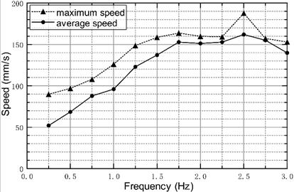
In the fundamental motion test, we investigated the speed of the robotic fish swimming under varied flipping frequencies from 0.25 Hz to 3.0 Hz with 14.8 volts. Figure 11 depicts the outcome of this investigation. During the time spent swimming from one side of the pool to the other, the highest speed is represented by the red line, while the average speed is shown by the black line. According to the findings, the maximum and average speed rise with an increase in frequency beginning at 0.25 Hz and reaching their highest value at 2.5 Hz. After reaching their maximum value, the speed begins to decline with an increase in frequency beyond 2.5 Hz. The robotic fish's greatest speed was 187.7 millimeters per second at a frequency of 2.5 hertz, while its average speed was 163.2 millimeters per second.
3.3.2. Trajectory offset correction test
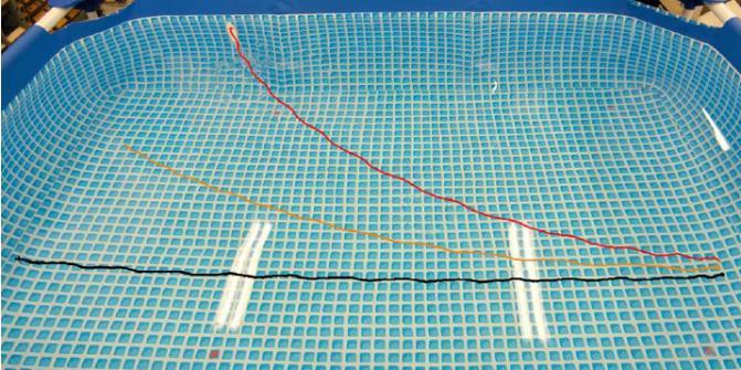
In this experiment, we sought to produce linear swimming motion by modifying the flipping duty cycle of the tail swing. This was done so that the tail would swing back and forth more often. Every one of the tests was run at a frequency of 2 Hz and a voltage of 14.8 volts. The fish motion trajectory is shifted to the right as a result of the fishtails erratic swing, which leads it to swing unevenly. In the first experiment, we tested at a flipping duty cycle of fifty percent, and the trajectory of that test is depicted as the red line in Figure 12. The path of the motion is altered such that it now goes to the right. In the second experiment, we tested at a flipping duty cycle of 52.5%, and the trajectory that was produced as a result is depicted by the yellow line. The degree to which the motion trajectory was deflected was improved compared to the first test. In the third experiment, we tested at a flipping duty cycle of 55%, and the trajectory that was produced as a consequence is depicted by the black line. The course will take you almost directly ahead.
3.3.3. Steering motion test
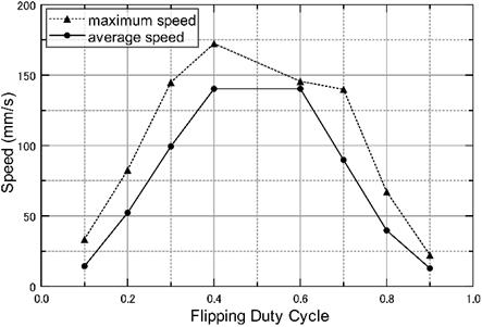
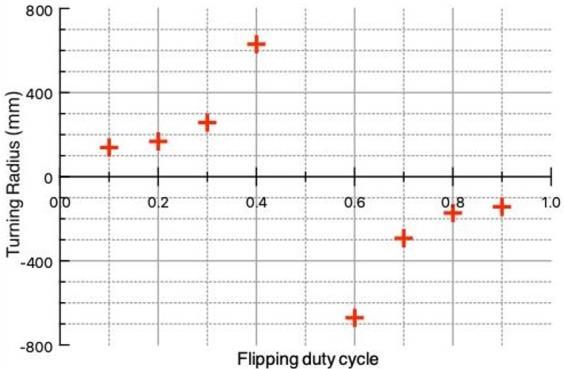
In this section, we evaluated the robotic fish’s capacity to turn at a frequency of 2 hertz and a voltage of 14.8 volts using a variety of flipping duty cycles. The duty cycle of the pulse current on both sides caused the motion trajectory of the fish to bend to the right or left side, depending on which side it was on. In the same way that we evaluated the turning radius before, this time we checked the speed of movement at 10%, 20%, 30%, 40%, 60%, 70%, 80%, and 90% of the flipping duty cycle. Figure 13(a) depicts the findings of a study that compared the maximum and average speeds achieved at varying flipping duty cycles. The blue line represents the typical speed, while the red line illustrates the highest possible speed. The tendency of the bell curve may be seen by looking at the relationship between the average speed and the flipping duty cycle. This connection is based on the average speed. Figure 13(b) presents the outcomes of the turning radius calculations performed for a variety of flipping duty cycles. When the value is positive, the turn will be to the left, and when the value is negative, the turn will be to the right. When the flipping duty cycle is 10%, the smallest possible radius for a rightward turn is 138.3 mm, and when the flipping duty cycle is 90%, the smallest possible radius for a leftward turn is 143.2 mm
A wireless bionic soft robotic fish using shape-memory alloy actuators (Kewei Ning)
4. CONCLUSION
In this work, the creation of a wireless bionic soft robotic fish was discussed. The fish had a silicone tail and a body shell that included a control circuit and a battery. SMA wire actuators were used to move the fish. The artificial fish swam in a behavior known as a BCF mode, which is frequently observed in real fish. On both sides of the silicone tail, SMA wires were inserted. These wires were utilized to drive the silicone tail, which enabled flexible fin flipping movement that imitated a genuine fish. A 3D scanned model of a real fish was used to generate the form of the shell, which in turn allowed the robotic fish to swim in a more realistic manner.
A number of different swim tests were carried out in order to validate the robotic fish’s ability to swim. The difficulty with the tail motions having varying amplitudes was created by the unequal swinging actions of the tail. The issue was effectively resolved once the flipping duty cycle was adjusted. The robotic fish was able to achieve an average swimming speed of 163.2 mm/s when the frequency was set to 2.5 Hz. In addition, the minimum radius for a right turn was 138.3 mm when the flipping duty cycle was 10%, while the minimum radius for a left turn was 143.2 mm when the flipping duty cycle was 90%. The swimming path followed something that was very close to a straight line because the duty cycle was set at 55%. Adjusting the flipping duty cycle for the SMA actuator control allowed us to accomplish straight-line propulsion in water despite the uneven swinging of the tail. This was made possible by the SMA.
The problem of varying amplitudes of tail swinging motion was created by the inherent nonsymmetric structure of the soft-silicone body, which was a result of the hand manufacture of the tail. This structure made it impossible to create a perfectly symmetric body for the tail. In the next research, we are going to implement machine learning in order to adaptively regulate the robot. We are doing this in the hopes that the learning algorithm will be able to automatically correct for the unpredictability of the swimming motion that is brought on by the asymmetry of the body.
Acknowledgements
This research was made possible thanks to funding from the JSPS Grants-in-Aid for Scientific Research on Innovative Areas (research in a suggested research field) 18H05473, as well as the JSPS Grantsin-Aid for Scientific Research (B) 20H04214. The authors express gratitude to Professor Pitoyo Hartono for the discussion about intelligent control.
References
[1] C. Lee et al., “Soft robot review,” Int. J. Control. Autom. Syst., vol. 15, no. 1, pp. 3–15, Feb. 2017, doi: 10.1007/s12555-0160462-3.
[2] H. Bin, W. Zhipeng, and T. Haifeng, “Review of soft robot,” Tongji Daxue Xuebao/Journal Tongji Univ., vol. 42, no. 10, pp. 1596
1603, 2014.
[3] S. Saito, Y. Katoh, H. Kokubo, M. Watanabe, and S. Maruo, “Development of a soft actuator using a photocurable ionic gel,” J. Micromechanics Microengineering, vol. 19, no. 3, Mar. 2009, doi: 10.1088/0960-1317/19/3/035005.
[4] Y. Hara, S. Maeda, R. Yoshida, and S. Hashimoto, “Development of novel self-oscillating molecular robot fueled by organic acid,” in 2009 IEEE/RSJ International Conference on Intelligent Robots and Systems, Oct. 2009, pp. 2223–2227. doi: 10.1109/IROS.2009.5354793.
[5] R. K. Katzschmann, A. D. Marchese, and D. Rus, “Hydraulic autonomous soft robotic fish for 3D swimming,” in Experimental Robotics, Springer International Publishing, 2016, pp. 405–420. doi: 10.1007/978-3-319-23778-7_27.
[6] N. D. Naclerio et al., “Controlling subterranean forces enables a fast, steerable, burrowing soft robot,” Sci. Robot., vol. 6, no. 55, Jun. 2021, doi: 10.1126/scirobotics.abe2922.
[7] M. Calisti et al., “An octopus-bioinspired solution to movement and manipulation for soft robots,” Bioinspiration and Biomimetics, vol. 6, no. 3, Sep. 2011, doi: 10.1088/1748-3182/6/3/036002.
[8] H.-T. Lin, G. G. Leisk, and B. Trimmer, “GoQBot: a caterpillar-inspired soft-bodied rolling robot,” Bioinspiration and Biomimetics, vol. 6, no. 2, Jun. 2011, doi: 10.1088/1748-3182/6/2/026007.
[9] C. Laschi, M. Cianchetti, B. Mazzolai, L. Margheri, M. Follador, and P. Dario, “Soft robot arm inspired by the octopus,” Adv. Robot., vol. 26, no. 7, pp. 709–727, Jan. 2012, doi: 10.1163/156855312X626343.
[10] H. F. Schulte, “The characteristics of the McKibben artificial muscle,” Appl. Extern. power prosthetics Orthot., pp. 94–115, 1961.
[11] C.-P. Chou and B. Hannaford, “Measurement and modeling of McKibben pneumatic artificial muscles,” IEEE Trans. Robot. Autom., vol. 12, no. 1, pp. 90–102, 1996, doi: 10.1109/70.481753.
[12] D. Rus and M. T. Tolley, “Design, fabrication and control of soft robots,” Nature, vol. 521, no. 7553, pp. 467–475, May 2015, doi: 10.1038/nature14543.
[13] E. Steltz, A. Mozeika, N. Rodenberg, E. Brown, and H. M. Jaeger, “JSEL: jamming skin enabled locomotion,” in 2009 IEEE/RSJ International Conference on Intelligent Robots and Systems, Oct. 2009, pp. 5672–5677. doi: 10.1109/IROS.2009.5354790.
[14] S. A. Morin, R. F. Shepherd, S. W. Kwok, A. A. Stokes, A. Nemiroski, and G. M. Whitesides, “Camouflage and display for soft machines,” Science (80-. )., vol. 337, no. 6096, pp. 828–832, Aug. 2012, doi: 10.1126/science.1222149.
[15] C. D. Onal and D. Rus, “Autonomous undulatory serpentine locomotion utilizing body dynamics of a fluidic soft robot,” Bioinspiration and Biomimetics, vol. 8, no. 2, Mar. 2013, doi: 10.1088/1748-3182/8/2/026003.
[16] M. T. Tolley et al., “A resilient, untethered soft robot,” Soft Robot., vol. 1, no. 3, pp. 213
223, Sep. 2014, doi: 10.1089/soro.2014.0008.
[17] B. Mosadegh et al., “Pneumatic networks for soft robotics that actuate rapidly,” Adv. Funct. Mater., vol. 24, no. 15, pp. 2163
2170, Apr. 2014, doi: 10.1002/adfm.201303288.
[18] Y. Nakabo, “Biomimetic soft robot using artificial muscle, in tutorial’electro-active polymer for use in robotics,” Procedings IEEE/RSJ Int. Conf. Intell. Robot. Syst. Sendai, 2004, 2004.
[19] K. Ogawa, Y. Nakabo, T. Mukai, K. Asaka, and N. Ohnishi, “A snake-like swimming robot with an artificial muscle,” Trans. Soc. Instrum. Control Eng., vol. 42, no. 1, pp. 80–89, 2006, doi: 10.9746/sicetr1965.42.80.
[20] Y. Nakabo, T. Mukai, and K. Asaka, “Kinematic modeling and visual sensing of multi-DOF robot manipulator with patterned artificial muscle,” in Proceedings of the 2005 IEEE International Conference on Robotics and Automation, 2005, pp. 4315
4320. doi: 10.1109/ROBOT.2005.1570784.
[21] H. Sawada, “Tactile display using the micro-vibration of shape-memory alloy wires and its application to tactile interaction systems,” in Pervasive Haptics, Tokyo: Springer Japan, 2016, pp. 57–77. doi: 10.1007/978-4-431-55772-2_4.
[22] Y. Du, M. Xu, E. Dong, S. Zhang, and J. Yang, “A novel soft robot with three locomotion modes,” in 2011 IEEE International Conference on Robotics and Biomimetics, Dec. 2011, pp. 98–103. doi: 10.1109/ROBIO.2011.6181269.
[23] S. Seok, C. D. Onal, K.-J. Cho, R. J. Wood, D. Rus, and S. Kim, “Meshworm: a peristaltic soft robot with antagonistic nickel titanium coil actuators,” IEEE/ASME Trans. Mechatronics, vol. 18, no. 5, pp. 1485–1497, Oct. 2013, doi: 10.1109/TMECH.2012.2204070.
[24] Z. Wang, G. Hang, J. Li, Y. Wang, and K. Xiao, “A micro-robot fish with embedded SMA wire actuated flexible biomimetic fin,” Sensors Actuators A Phys., vol. 144, no. 2, pp. 354–360, Jun. 2008, doi: 10.1016/j.sna.2008.02.013.
[25] H. Shaw and A. Thakur, “Shape memory alloy based caudal fin for a robotic fish: Design, fabrication, control and characterization,” in Proceedings of the Advances in Robotics 2019, 2019, pp. 1–6.
[26] X. Chen, H. Shigemune, and H. Sawada, “An untethered bionic robotic fish using SMA actuators,” in 2020 IEEE International Conference on Mechatronics and Automation (ICMA), Oct. 2020, pp. 1768–1773. doi: 10.1109/ICMA49215.2020.9233798.
[27] M. Sfakiotakis, D. M. Lane, and J. B. C. Davies, “Review of fish swimming modes for aquatic locomotion,” IEEE J. Ocean. Eng., vol. 24, no. 2, pp. 237–252, Apr. 1999, doi: 10.1109/48.757275.
[28] J. Shintake, V. Cacucciolo, H. Shea, and D. Floreano, “Soft biomimetic fish robot made of dielectric elastomer actuators,” Soft Robot., vol. 5, no. 4, pp. 466–474, Aug. 2018, doi: 10.1089/soro.2017.0062.
[29] K. Otsuka and X. Ren, “Recent developments in the research of shape memory alloys,” Intermetallics, vol. 7, no. 5, pp. 511–528, May 1999, doi: 10.1016/S0966-9795(98)00070-3.
[30] “Fish 03.” https://cults3d.com/en/3d-model/various/fish-03 (accessed Dec. 20, 2020).
Biographies Of Authors
Kewei Ning received his bachelor of electronic information engineering from the Wuhan University of Technology in 2019. Currently, he is a master’s student in Sawada Laboratory at Waseda University. His research interests include bionic robots and nurture networks. He can be contacted at ningkewei1096@akane.waseda.jp.
Sawada Hideyuki received his Ph D in engineering from Waseda University in 2018. He is currently an assistant professor in the Department of Electrical Engineering, Shibaura Institute of Technology. He was an assistant professor in Waseda University (2018-2019). He was a reviewer of IEEE Transactions on Mechatronics, Soft Robotics Journal, IROS2016, ICRA2017, Robotics and Automation Letters (IROS2017, ICRA2018). He is a member of IEEE and The Japan Society of Mechanical Engineering. He can be contacted at sawada@waseda.jp.
A wireless bionic soft robotic fish using shape-memory alloy actuators (Kewei Ning)
IAES International Journal of Robotics and Automation (IJRA)
Vol. 11, No. 4, December 2022, pp. 288 303
ISSN: 2722-2586, DOI: 10.11591/ijra v11i4 pp288-303