2 minute read
To verify fiber performance, a concrete mixture with

with the reduction in the average crack width. FRC has also been shown to retain significant residual strength even after a large number of freeze/thaw cycles.
Test Method for FRC Performance
Advertisement
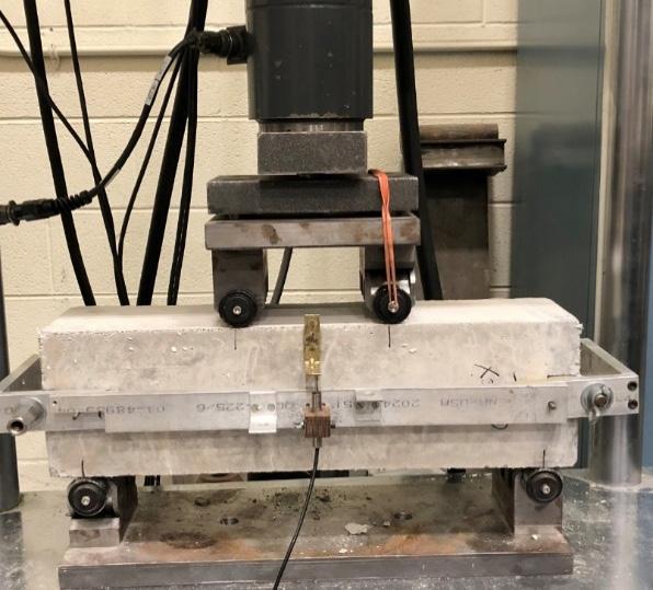
The primary test method used to link the performance benefit of macrofibers on concrete pavement design is ASTM C1609-12 (Figure 6 and Figure 7), which is very similar to flexural beam test (ASTM C78) with several main differences:
• the test is controlled by mid-span vertical displacement instead of load;
• the test is continued beyond when a macro-crack forms to a total displacement equal to L/150, where L is the span length. Typically, this is 0.12 inch (3 mm) deflection. • ASTM C1609 specifies a low friction roller assembly (ASTM C1812); • the 6 inch (150 mm) square cross-section beam is recommended for pavement applications over the 4 inch (100 mm) beam depth; and
the specification should state a testing age (e.g., 14 days)
and identify the target (average) residual strength (f 150 ) for the FRC material. Note: experience has shown that later
testing ages (e.g., 28 days) may require a stiffer and higher capacity testing frame to properly control the ASTM C1609 test.
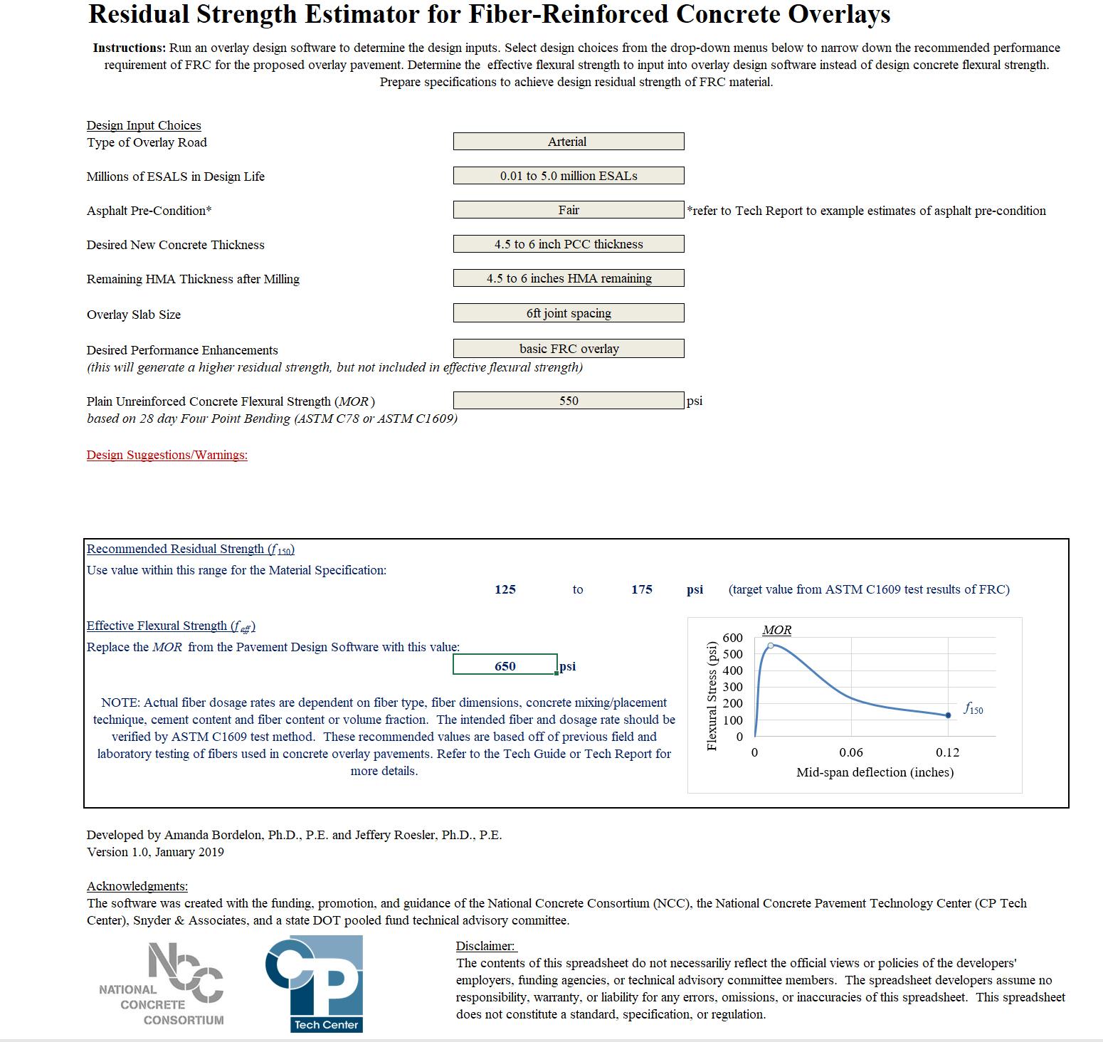
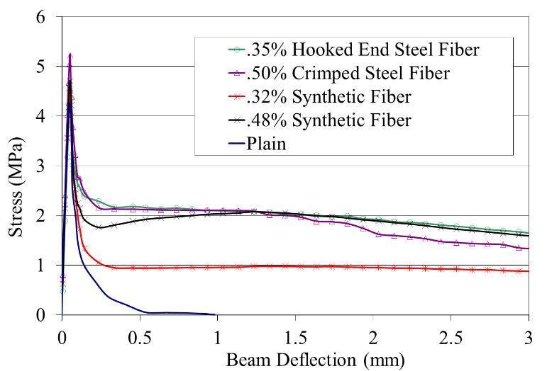
From ASTM C1609-12, the residual strength (f 150 ) is calculated from the load-deflection plot (Figure 7). P 150 is the corresponding load when the displacement reaches a
value of L/150 (Figure 6), L is the span of the beam between the supports, b is the width of the beam, and d is the height of the beam:
f150 = P 150 L bd 2
While alternative test methods to characterize the postcracking performance of FRC have been proposed, it is recommended [12] that ASTM C1609 be used to evaluate the residual strength value for a given concrete mixture, fiber type, and fiber content for concrete pavement overlay designs.
Mixture Proportioning and Construction Modifications for FRC Overlays
In general, for the typical low to moderate fiber dosages used for FRC pavement overlays (e.g., <0.5% by volume), the concrete mix design does not necessarily need to be adjusted except for accommodating the volume of fibers. Best practices for standard proportioning of concrete paving mixtures should be followed. Trial batches are always recommended to assess if the FRC mix design is sufficient for uniform mixing, transporting, casting/placement, consolidation, and finishing.
Figure 6. Geometry of the ASTM C1609 beam setup. Typical dimensions include a cross section depth d of 6 in., width b of 6 in., and span L of 18 in.
Increasing the total cementitious content and/or introducing a water-reducer may be warranted to ensure a good fiber-paste bond and adequate workability. The w/cm ratio should be still selected for the desired workability, strength, and durability performance. As an example, FRC used for concrete overlays have included the following mixture proportions: w/cm ratios of 0.38 to 0.45, air contents of 5% to 7%, supplementary cementitious material (e.g., fly ash or slag) replacements of cement of 15% to 35%, and well-graded aggregates [13].
Macrofibers can be successfully introduced at any phase of the mixing process but the manufacturer’s recommendation should be initially followed. Fiber balling, clumping, or entanglement has occurred with any or multiple combinations of the following conditions: