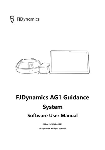
FJDynamics AG1 Guidance System Software User Manual Nov, 2024 | V24.105.1 ©FJDynamics. All rights reserved.
FJDynamics AG1 Guidance System Software User Manual
©FJDynamics. All rights reserved..
FJDynamics AG1 Guidance System Software User Manual
Copyright Notice: FJDynamics reserves the copyright for this manual and all contents herein. No part of this manual may be reproduced, extracted, reused, or reprinted in any form or by any means without the prior written permission of FJDynamics. This manual is subject to change without notice.
Read Before Use: Operate in strict accordance with this manual. If you have any questions during use, contact our customer service.
Disclaimer: The purchased products, services, and features are stipulated by the contract. All or part of the products, services, and features described in this manual may not be within the scope of your purchase or usage. Unless otherwise specified in the contract, all the content in this manual is provided "AS IS" without warranties of any kind, express or implied. The content of this manual is subject to change due to product upgrades and other reasons. FJDynamics reserves the right to modify the content of this manual without notice. This manual only provides guidance for use of this product. Every effort has been made in the preparation of this manual to ensure accuracy of the content, but no information in this manual constitutes a warranty of any kind, express or implied.
©FJDynamics. All rights reserved.
FJDynamics AG1 Guidance System Software User Manual
Safety Instructions Before using this product, ensure that you have read and understood all the operation instructions and precautions in this FJDynamics AG1 Guidance System Software User
Manual.
Safety Instructions Once the control terminal is started, the following popup appears, informing you of safety risks to which you must pay more attention.
Operator 1. People under eighteen or not meeting the age requirement of local laws and regulations are not allowed to operate this product. 2. Do not drive under the influence of medicines, alcohol, and drugs. 3. Do not drive when feeling tired. 4. Operators must hold the driving licenses as required by local laws and regulations.
Operating Environment 1. Drive in an open field far from the crowd and ensure that there are no irrelevant personnel or vehicles in the operation area. 2. Stay away from people, livestock, obstacles, wires, tall buildings, airports, and signal towers to avoid interference with signals. 3. Do not operate in extreme weathers such as heavy rain, thick fog, snow, lightning, and strong wind.
©FJDynamics. All rights reserved..
FJDynamics AG1 Guidance System Software User Manual
Operation 1. Do not get on or off the vehicle during operation. 2. Monitor the operation condition in real time during operation to ensure timely intervention when necessary.
Inspection 1. Ensure that there is sufficient oil in the fuel tank of the vehicle. 2. Ensure that all cables are intact. If any damage is found, stop the operation and replace the cable.
Others 1. Disassembling the product housing without authorization may invalidate the warranty. 2. Damage caused by force majeure events, such as lightning strikes, overvoltage, and collision, is not covered by the warranty. 3. Connect the devices strictly in accordance with this manual. When connecting cables such as data cables, hold the end of the plug and gently plug or unplug it. Do not pull the plug by force or twist it, which may break the pins. 4. Follow the power supply requirements for this product (system). The supply voltage for the control terminal and the electric steering wheel is 9 V–36 V.
©FJDynamics. All rights reserved.
FJDynamics AG1 Guidance System Software User Manual
Preface Use of Manual This manual describes how to use FJDynamics AG1 Guidance System in concise, simple, and clear language, so that users can master each operation procedure easily, quickly, and accurately.
Technical Support Starting from the date of purchase, users will be provided with the technical support and upgrade services from FJDynamics. Contact FJDynamics by any of the following methods: • Tel: +1 833-330-6660 (US) • Tel: +496 931 090 130 (Europe) • Official website: https://www.fjdynamics.com
©FJDynamics. All rights reserved..
FJDynamics AG1 Guidance System Software User Manual
Contents Chapter 1 Product Overview ........................................................................................................................................................ 1 1 Main Components .......................................................................................................................................................... 1 2 Control Terminal Ports ................................................................................................................................................... 1 Chapter 2 Software Operation Instructions .............................................................................................................................. 2 1 Workflow Overview ........................................................................................................................................................ 2 2 Installation and Commissioning .................................................................................................................................. 2 2.1 Selecting a Language ..................................................................................................................................... 2 2.2 Sign-up/Login .................................................................................................................................................. 3 2.3 Entering Installation Information ................................................................................................................. 3 2.4 Home Screen .................................................................................................................................................... 4 2.5 Connecting to a GNSS Receiver ................................................................................................................... 5 2.6 Connecting to a Signal Source ..................................................................................................................... 6 2.7 Setting Vehicle Parameters ........................................................................................................................ 12 2.8 Setting Implement Parameters.................................................................................................................. 15 2.9 Calibrating the Implement ......................................................................................................................... 18 3 Preparations .................................................................................................................................................................. 19 3.1 Checking the Signal Source Connection ................................................................................................. 19 3.2 Checking the Task Configuration .............................................................................................................. 20 3.3 Creating a Boundary and Guidance Line ................................................................................................ 24 4 Starting the Task........................................................................................................................................................... 40 4.1 Home Screen Elements ............................................................................................................................... 40 4.2 Task Operations ............................................................................................................................................ 41 5 Applications................................................................................................................................................................... 52 5.1 Remote Debugging...................................................................................................................................... 52 5.2 Camera (Optional) ........................................................................................................................................ 53 5.3 Data Transfer ................................................................................................................................................. 54 5.4 NMEA (Optional) .......................................................................................................................................... 58 5.5 ISOBUS (Optional) ........................................................................................................................................ 59 6 Others ............................................................................................................................................................................. 60 6.1 Device Settings ............................................................................................................................................. 60 6.2 Field ................................................................................................................................................................. 68 6.3 Diagnostics Center ....................................................................................................................................... 73 6.4 Universal ......................................................................................................................................................... 77 6.5 System............................................................................................................................................................. 84 Chapter 3 Common Faults and Solutions ............................................................................................................................... 88 Chapter 4 Main Hardware Specifications ............................................................................................................................... 89
©FJDynamics. All rights reserved.
FJDynamics AG1 Guidance System Software User Manual
Chapter 1 Product Overview 1 Main Components
Figure 1. Main components 1
Control terminal
2
GNSS receiver
3
Serves as the human-machine interface, and vehicle control and communication terminal. Receives satellite signals to obtain the vehicle location.
ISOBUS
Wireless communication of ISOBUS data with the
module(optional)
control terminal.
2 Control Terminal Ports
Figure 2. Control terminal ports
1 ©FJDynamics. All rights reserved.
FJDynamics AG1 Guidance System Software User Manual
Chapter 2 Software Operation Instructions 1 Workflow Overview This chapter describes the main operation processes and related functions of FJDynamics AG1 Guidance System. Before using the system for the first time, you need to complete the installation, commissioning, and preparations to start the operation successfully.
2 Installation and Commissioning Use the following workflow to install and commission the system for the first time: Select a language → Sign up and log in → Enter installation information → Connect to a GNSS Receiver → Connect to a signal source →Obtain heading* →Set the vehicle parameters → Calibrate the implement → Complete * Drive the vehicle straight ahead for a while, and the heading is obtained automatically. If not, choose MENU > SYSTEM > Heading calibration.
2.1 Selecting a Language Power on the control terminal, select a language, and tap Next to open the sign-up/login screen.
Figure 3. Select a language
©FJDynamics. All rights reserved. 2
FJDynamics AG1 Guidance System Software User Manual
2.2 Sign-up/Login The sign-up/login screen is displayed in the language you selected. Sign up: For the first time use, you need to sign up. Tap Register to open the sign-up screen, enter your email address, verification code, and password, and then read and agree to the User Privacy Agreement. Log in: If you have an account already, you can log in directly by entering your username (email address) and password. Forgot password: If you forgot your password, tap Forgot Password to reset the password. Enter your email address, verification code, and new password, and then tap Login to enter the home screen of the system. Select country/region: The system automatically selects the country or region based on your location, or you can tap
in the lower left corner and select your country or region.
Ensure that the country or region you selected is true, and we bear no responsibility for any consequences arising from your wrong selection.
Figure 4. Sign-up or login screen
2.3 Entering Installation Information For the first time use, you need to enter the user information and installation information. Note that the information you entered may have an impact on your aftersales service, so strictly follow the following procedure: Step 1: Enter the user information, and tap Next.
3 ©FJDynamics. All rights reserved.
FJDynamics AG1 Guidance System Software User Manual
Figure 5. Enter the user information Step 2: Enter the installation information, and tap Confirm.
Figure 6. Enter the installation information
2.4 Home Screen The home screen is displayed upon login. You can view the network connection and operation status in real time. For convenience, your account information is automatically saved locally, so that you are logged in automatically to open the home screen every time the system is powered on. Refer to section 4.1 "Home Screen Elements" for details.
©FJDynamics. All rights reserved. 4
FJDynamics AG1 Guidance System Software User Manual
Figure 7. Home screen
2.5 Connecting to a GNSS Receiver After entering the home screen first time, it will prompt "GNSS Receiver Antenna not connected ", you need to connect the GNSS Receiver before you start other operations. Step 1: Tap the Connect button, it will automatically jump to the GNSS Receiver connection.
Figure 8. Connecting to a GNSS Receiver prompt Step 2: Click the refresh button and select the GNSS Receiver (FJSNxxxxx) to pair and connect from the nearby devices.
5 ©FJDynamics. All rights reserved.
FJDynamics AG1 Guidance System Software User Manual
Figure 9. Pair and connect a GNSS Receiver If the pairing and connection fails, verify that the GNSS Receiver is not too far away or is receiving signal interference and try to re-pair the connection.
2.6 Connecting to a Signal Source After the GNSS Receiver is connected, connect to a correction signal source. Step 1: Choose MENU > DEVICE SETTINGS > Correction Source.
Figure 10. Select Correction Source Step 2: Tap Network RTK, Mobile Base Station RTK, SBAS, or PPP to initiate a connection request or set connection parameters. The connection mode you enabled is selected automatically the next time you log in.
©FJDynamics. All rights reserved. 6
FJDynamics AG1 Guidance System Software User Manual
Figure 11. Connect to a signal source 2.6.1 Network RTK To enable the network RTK mode, tap Network RTK, and the NTRIP and NRTK options are displayed. NTRIP Tap NTRIP, and enter information in the popup dialog. NTRIP host: Enter the host and port, and tap Get Source. The node with the strongest signal strength is displayed automatically in the Source Node box. NTRIP account: Enter your account and password, and tap OK to complete the connection.
Figure 12. Enter NTRIP information NRTK Tap NRTK, and the NRTK account bound is automatically logged in.
7 ©FJDynamics. All rights reserved.
FJDynamics AG1 Guidance System Software User Manual
Figure 13. Select NRTK Note: Network RTK requires inserting a SIM card for use and cannot connect to WIFI. Check whether the mode is available in your region by contacting us as described in section "Technical Support" or contacting the local dealer. 2.6.2 Mobile Base Station RTK For the mobile base station RTK mode, the connection method is selected depending on the base station type. Pairing via Code Tap Mobile Base Station RTK, and select Pairing via Code. In the popup dialog, enter the frequency code of the base station and tap OK. For details about the base station's frequency code, refer to its user manual. Applicable base stations: FJDynamics mobile base stations whose service codes start with BS or BSA. You can also set public frequencies in the popup dialog. The frequencies must be 410 MHz to 470 MHz with a maximum of five decimal places. If the base station's service code starts with BSA, public frequency settings are not supported.
©FJDynamics. All rights reserved. 8
FJDynamics AG1 Guidance System Software User Manual
Figure 14. Pair via code Pairing via Frequency Tap Mobile Base Station RTK, and select Pairing via Frequency. In the popup dialog, enter the frequency of the base station and tap OK. The frequency must be 410 MHz to 470 MHz with a maximum of five decimal places. For details about the base station's frequency, refer to its user manual. Applicable base stations: FJDynamics high-power base stations whose service codes start with FQ.
Figure 15. Pair via frequency Pairing with Base Stations of Other Brands Power on the base station, and set its frequency, over-the-air baud rate, and radio communication protocol on the base station. Tap Mobile Base Station RTK, and select
9 ©FJDynamics. All rights reserved.
FJDynamics AG1 Guidance System Software User Manual
Other Base Station. In the popup dialog, set the same frequency, over-the-air baud rate, and radio communication protocol, and then tap OK. For details about the parameter settings of the base station, refer to its user manual.
Figure 16. Pair with base stations of other brands Base stations of other brands must support the following features: Frequency: 410–470 MHz Baud rate: 4,800 bps/ 9,600 bps/ 19,200 bps Radio communication protocol: Transparent-EOT/ TRIMMARK3/ TRIMTALK Differential data format: RTCM 2.X / 3.X Note: 1. Base station pairing may take up to 3 minutes. 2. If RTK connection keeps failing, try switching the RTK connection mode a few times. 2.6.3 SBAS Tap SBAS, and select WAAS, MSAS, EGNOS, GAGAN, or SDCM. The operation cannot be started until connected is displayed at the right of SBAS. To switch to a different signal source, tap the source, and then tap OK in the popup dialog.
©FJDynamics. All rights reserved. 10
FJDynamics AG1 Guidance System Software User Manual
Figure 17. SBAS connection established Note: The operation cannot be started when RTK Status is 1 in Diagnostics Center > Scenario. Once the connection is established, RTK Status becomes 2 and the signal source icon in the upper right corner becomes "S00-S20". 2.6.4 PPP Tap the PPP option. The operation cannot be started until the PPP has completed configuration and convergence.
Figure 18. Connecting to a PPP PPP connection status Phase
Correction Source
Configuring
11 ©FJDynamics. All rights reserved.
Status bar
Prompt
FJDynamics AG1 Guidance System Software User Manual
Configured
Converging
Converged
Note: The convergence time is about 20min, please wait patiently.
2.7 Setting Vehicle Parameters To add, delete, modify, check, upload and synchronize the vehicle information, choose MENU > DEVICE SETTINGS > Vehicle Library.
Figure 19. Select Vehicle Library 2.7.1 Parameter Settings To enter the vehicle settings screen, tap New or Edit. Enter the basic information on the Information tab, and then tap Next. Measure and enter the vehicle parameters on the Parameters tab, and then tap Next. Check the vehicle information on the Summary tab, and then tap Save.
©FJDynamics. All rights reserved. 12
FJDynamics AG1 Guidance System Software User Manual
Figure 20. Vehicle library
Figure 21. Information tab
13 ©FJDynamics. All rights reserved.
FJDynamics AG1 Guidance System Software User Manual
Figure 22. Parameters tab
Figure 23. Summary tab 2.7.2 Other Actions Delete To delete the vehicle information, tap a vehicle, and then tap Delete. The deleted information cannot be restored. This action is unavailable when there is only one vehicle in the vehicle library. Synchronize Tap the Sync button to synchronize the cloud and local data with each other.
©FJDynamics. All rights reserved. 14
FJDynamics AG1 Guidance System Software User Manual
2.8 Setting Implement Parameters To add, delete, modify, check, upload, synchronize, and calibrate the implement information, choose MENU > DEVICE SETTINGS > Implement Library.
Figure 24. Select Implement Library 2.8.1 Parameter Settings To enter the implement settings screen, tap New or Edit. Select the implement type on the Type tab, and then tap Next. Enter the basic information on the Information tab, and then tap Next. Measure and enter the implement parameters on the Parameters tab, and then tap Next. Check the implement information on the Summary tab, and then tap Save.
Figure 25. Implement library
15 ©FJDynamics. All rights reserved.
FJDynamics AG1 Guidance System Software User Manual
Figure 26. Type tab
Figure 27. Information tab
Figure 28. Parameters tab
©FJDynamics. All rights reserved. 16
FJDynamics AG1 Guidance System Software User Manual
Figure 29. Summary tab 2.8.2 Calibration To enter the implement calibration screen, tap Calibration. Refer to section 2.9 "Calibrating the Implement" for details. 2.8.3 Other Actions Delete To delete the implement information, tap an implement, and then tap Delete. The deleted information cannot be restored. This action is unavailable when there is only one implement in the implement library. Synchronize Tap the Sync button to synchronize the cloud and local data with each other.
17 ©FJDynamics. All rights reserved.
FJDynamics AG1 Guidance System Software User Manual
2.9 Calibrating the Implement Calibrate the implement if there is any skip or overlap between adjacent trajectories. Choose MENU > DEVICE SETTINGS > Implement Calibration.
Figure 30. Calibrate the implement Automatic calculation of correction value The system works out the correction value automatically based on the skip or overlap values you entered. Manual calculation of correction value Alternatively, you can calculate and enter the correction value based on your experience or demand. Correct Tap Correct, and the correction value is added to the cumulative correction value. You can tap Correct repeatedly. Empty To clear the automatic or manual correction value, as well as the cumulative correction value, tap Empty.
©FJDynamics. All rights reserved. 18
FJDynamics AG1 Guidance System Software User Manual
Figure 31. Manual calculation The above installation and commissioning aims to ensure high-accuracy navigation. Before any operation, you still need to make the following preparations.
3 Preparations Make the following preparations before any operation: Check the signal source connection → check the task configuration (create or select a field → create or select a task → create or select a boundary → create or select a guidance line) → check the implement configuration → obtain heading → start the operation.
3.1 Checking the Signal Source Connection Before any operation, check the signal source connection. Refer to section 2.6 "Connecting to a Signal Source" for details.
19 ©FJDynamics. All rights reserved.
FJDynamics AG1 Guidance System Software User Manual
3.2 Checking the Task Configuration To preview and switch the fields, tasks, boundaries, guidance lines, and implements, tap Overview on the home screen. Refer to section 6.2 "Field" for details on how to add, delete, modify, check, and manage the fields, tasks, boundaries, and guidance lines.
Figure 32. Overview 3.2.1 Creating or Selecting a Field The field name, field map, field area, client name, and farm name are displayed on the left of the Overview screen. Tap
to switch to another field or create a field.
Figure 33. Switch the field
©FJDynamics. All rights reserved. 20
FJDynamics AG1 Guidance System Software User Manual
Figure 34. Create a field 3.2.2 Creating or Selecting a Task The task name, task type, operation area, and completion rate are displayed in the Task section on the right of the Overview screen. Tap
to switch to another task bound to
the same field or create a task.
Figure 35. Switch the task
21 ©FJDynamics. All rights reserved.
FJDynamics AG1 Guidance System Software User Manual
Figure 36. Create a task 3.2.3 Selecting a Boundary The boundary name, signal source used, and creation time are displayed in the Boundary section on the right of the Overview screen. Tap
to switch to another boundary bound
to the same field. If no boundary is required for the operation, keep the boundary part empty. Refer to section 3.3 "Creating a Boundary and Guidance Line" for details on boundary creation.
Figure 37. Switch the boundary
©FJDynamics. All rights reserved. 22
FJDynamics AG1 Guidance System Software User Manual
3.2.4 Selecting a Guidance Line The guidance line name and type, signal source used, and creation time are displayed in the Guidance Line section on the right of the Overview screen. Tap
to switch to
another guidance line bound to the same field. If no guidance line is required for the operation, keep the guidance line part empty. Refer to section 3.3 "Creating a Boundary and Guidance Line" for details on guidance line creation.
Figure 38. Switch the guidance line 3.2.5 Checking the Implement Configuration The implement name, working width, and skip/overlap are displayed in the Implement section on the right of the Overview screen. Tap
to switch to another implement. Refer
to section 2.8 "Setting Implement Parameters" for details on implement creation.
Figure 39. Switch the implement
23 ©FJDynamics. All rights reserved.
FJDynamics AG1 Guidance System Software User Manual
3.3 Creating a Boundary and Guidance Line To record the boundary or create four types of guidance lines, tap Line Creation on the home screen. Tap
in the lower left corner to record the operation while the boundary
and guidance line are created.
Figure 40. Create a guidance line 3.3.1 Creating a Boundary Tap
on the right, and select the leftmost, center, or rightmost position as the reference
based on the boundary and implement position relation.
Figure 41. Select the boundary recording reference
©FJDynamics. All rights reserved. 24
FJDynamics AG1 Guidance System Software User Manual
Drive around the field and return to the start point to record a complete boundary.
Figure 42. Record the boundary When recording the boundary, you can tap
in the upper right corner of the Boundary
section to edit the boundary name, headland distance and offset direction.
Figure 43. Set the boundary
25 ©FJDynamics. All rights reserved.
FJDynamics AG1 Guidance System Software User Manual
The system determines whether the boundary recorded can be used. If the boundary cannot be used directly, the system processes it as follows. Boundary
x ≤50 m
start point to point 50 m < x
boundary
Illustration
point and the end point with a straight line.
the end
Special
Processing
Connect the start
Distance x from the
System
Resume the recording.
Boundary
Resume the
length < 80 m
recording.
Boundary too narrow Multiple subareas within
Record the boundary again.
the boundary 3.3.2 Creating a Guidance Line The process to create a guidance line depends on the guidance line mode you select. Now there are the straight line, the A+ line, the curve, the pivot mode, the headland and the diagonal line.
©FJDynamics. All rights reserved. 26
FJDynamics AG1 Guidance System Software User Manual
Figure 44. guidance line modes 3.3.2.1 AB straight line mode Set point A and point B to create a straight line. This mode is applicable to regularly shaped fields. Access the boundary and guidance line creation screen, and tap
to select the AB
straight line mode. Drive the vehicle to the start point, and tap
to set the current
position as point A.
Figure 45. Set point A Stay in the manual mode, and drive the vehicle for at least 10 m. Tap position as point B, or tap
27 ©FJDynamics. All rights reserved.
to cancel point A.
to set the current
FJDynamics AG1 Guidance System Software User Manual
Figure 46. Set point B Tap
to generate and import the AB line, and the system goes to the home screen and
uses the AB line automatically. You can also keep driving the vehicle to another point and tap
to change point B to the new position, or tap
to cancel the guidance line creation.
Figure 47. Import the guidance line When creating a guidance line, you can tap
in the upper right corner of the Guidance
Line section to set the guidance line name.
©FJDynamics. All rights reserved. 28
FJDynamics AG1 Guidance System Software User Manual
Figure 48. Change the guidance line name Creating guidance lines while recording the boundary While recording the boundary, you can create AB straight guidance lines by following the same process mentioned above.
Figure 49. Create a guidance line while recording the boundary After a guidance line is created successfully, you can tap
in the Guidance Line section
to create a new guidance line. All AB lines created during the boundary recording are saved under the current field, and can be switched during a task operation. Refer to section 4.2.3 "Switching Boundaries or Guidance Lines" for details. After the boundary is recorded, the system goes to the home screen and uses the last AB line imported automatically.
29 ©FJDynamics. All rights reserved.
FJDynamics AG1 Guidance System Software User Manual
Figure 50. Record boundary edges as the guidance lines 3.3.2.2 A+ line mode Set point A and the heading of the vehicle to create a straight guidance line. This mode is applicable to large fields and operations by multiple operators. Access the guidance line creation screen, and tap vehicle to the start point, and tap
to select the A+ line mode. Drive the
to set the current position as point A.
Figure 51. Set point A You can use your current heading as the heading for creating an A+ line, or enter the heading manually. a. Tap
on the map to set the current heading as the heading of the A+ line.
©FJDynamics. All rights reserved. 30
FJDynamics AG1 Guidance System Software User Manual
Figure 52. Use the current heading b. To enter a heading manually, tap
on the right panel, and a popup window appears.
Enter a heading relative to the true north in a clockwise direction. The heading must be in the range of 0–360°, with a maximum of four decimal places.
Figure 53. Enter the heading manually Tap
to generate and import the A+ line, and the system goes to the home screen and
uses the A+ line automatically. You can also keep driving the vehicle to another point and tap
to change point A to the new position, or tap
When creating a guidance line, you can tap
to cancel the line creation.
in the upper right corner to change the
guidance line name. 3.3.2.3 Curve mode Use the curved trajectory between point A and point B to generate a guidance line. This
31 ©FJDynamics. All rights reserved.
FJDynamics AG1 Guidance System Software User Manual
mode is applicable to irregularly shaped fields or special fields. Access the guidance line creation screen, and tap vehicle to the start point, and tap
to select the curve mode. Drive the
to set the current position as point A.
Figure 54. Set point A Stay in the manual mode, and drive along a curve for at least 10m. Tap current position as point B, or tap
to set the
to cancel point A.
Figure 55. Set point B When creating a guidance line, you can tap
in the upper right corner to change the
guidance line name. Tap
to import the curve line, and the system goes to the home screen and uses the
curve line automatically. You can also tap
to cancel the line creation.
©FJDynamics. All rights reserved. 32
FJDynamics AG1 Guidance System Software User Manual
Figure 56. Confirm the curve line Note: 1. Point A is the start point and point B is recommended to be a point on the headland at the other side of the field. 2. The system automatically extends the line segments beyond the two end points along the tangent directions of the two end points, so the line segments beyond the end points are straight lines. 3.3.2.4 Pivot mode Record an arc AB to determine the pivot point and radius. This mode is applicable to fields using the center-pivot irrigation method. Access the guidance line creation screen, and tap vehicle to the start point, and tap
to select the pivot mode. Drive the
to set the current position as point A.
Figure 57. Set point A
33 ©FJDynamics. All rights reserved.
FJDynamics AG1 Guidance System Software User Manual
Stay in the manual mode, drive along the circular field edge for at least 20 m, and then tap to set the current positon as point B.
Figure 58. Set point B Tap
to generate the pivot circle, or tap
to cancel the guidance line creation.
Figure 59. Generate the pivot circle After you tap
, a popup window appears. Enter the distance from the implement edge
to the field edge in the popup window, and tap OK to import the pivot circle. The system goes to the home screen and uses the pivot circle automatically. When creating a guidance line, you can tap
in the upper right corner to change the guidance line name and the
distance to the field edge.
©FJDynamics. All rights reserved. 34
FJDynamics AG1 Guidance System Software User Manual
Figure 60. Enter the distance to the field edge Note: During a task operation with a pivot pattern, when you are returning to the start point after finishing one circular path, stop the autosteering operation according to the on-screen instructions 20 m away from the start point, drive the vehicle manually to the next circular path, and repeat the above steps until operations along all circular paths are completed. 3.3.2.5 Headland Generate an inward offset guidance line based on the shape of the boundary. Suitable for work on the edge of the field, especially for irregular field. Access the guidance line creation screen, and tap
to select the Headland mode.
1.If the boundary has already been imported, a Headland will be generated based on the current imported boundary. If the boundary has not been imported or needs to be replaced, you can create or select the desired boundary to generate a Headland. After confirming the boundary, click the next button.
35 ©FJDynamics. All rights reserved.
FJDynamics AG1 Guidance System Software User Manual
Figure 61. Confirm a boundary 2.Select the Generate Headland method.
Figure 62. Two Headland generation methods (1) Generate Headland based on the whole boundary: The shape of Headland is basically the same as that of the boundaries. (2) Generate Headland based on part of the boundary: Select part of the line from the boundary to generate Headland. Tap Partial boundary line to select the two endpoints of a line on the boundary.
©FJDynamics. All rights reserved. 36
FJDynamics AG1 Guidance System Software User Manual
Figure 63. Select a partial edge of the boundary 3.Confirm the Reserved Safety Distance and the Headland Number. Reserved Safety Distance: Safe distance from the boundary during operation. Headland Number: Number of generated headlands.
Figure 64. Confirmation parameters 4.Confirm the settings to generate Headland.
37 ©FJDynamics. All rights reserved.
FJDynamics AG1 Guidance System Software User Manual
Figure 65. Headland operation interface Notes: 1) Headland close to the boundary is Reserved Safety Distance+Half of guidance line width from the boundary. 2) Headland are not available for data transfer via USB. You can choose to generate it again after USB transfer of the boundary. 3) The Headland Number can be modified in Menu-Field- Guidance Line.
Figure 66. Edit Headland 3.3.2.6 Diagonal line Diagonal line is generated for harrowing based on the shape of the boundary. By harrowing the field twice through the cross harrowing operation, the harrowing effect is flatter and the harrowing efficiency is higher. Access the guidance line creation screen, and tap
to select the Diagonal line mode.
1.If the boundary has already been imported, a Diagonal line will be generated based on the
©FJDynamics. All rights reserved. 38
FJDynamics AG1 Guidance System Software User Manual
current imported boundary. If the boundary has not been imported or needs to be replaced, you can create or select the desired boundary to generate a Diagonal line. After confirming the boundary, click the next button.
Figure 67. Confirm a boundary 2.Confirm the Reserved Safety Distance and the Turning Points Number. Reserved Safety Distance: Safe distance from the boundary during operation. Turning Points Number:The number of turns when driving diagonally from one side of the boundary to the other. The optimal number of turns will be automatically recommended during setup.
Figure 68. Confirmation parameters 3.Confirm the settings to generate Diagonal line. There will be a blue dotted line to guide you to the starting point of the job.
39 ©FJDynamics. All rights reserved.
FJDynamics AG1 Guidance System Software User Manual
Figure 69. Diagonal line operation interface Note:Diagonal line is not available for data transfer via USB. You can choose to generate it again after USB transfer of the boundary.
4 Starting the Task 4.1 Home Screen Elements
Figure 70. Home screen elements 1. Offset value: Displays the offset of the current path relative to the guidance line. 2. Signal strength icons: Shows the strength of the satellite signal (satellite tracking), RTK correction signal, or other correction source signals. 3. Error Messages: On the home screen, tap the red square with a number in the upper right corner to view the error messages.
©FJDynamics. All rights reserved. 40
FJDynamics AG1 Guidance System Software User Manual
4. Real-time task operation data: Shows the current task operation data, including, from left to right, the guidance line number, the total field area, the operated area, the completion ratio, the operation efficiency, and the current speed. 5. Camera button: Tap to turn on the Wi-Fi camera. Refer to section 4.2.9 "Turning on the Wi-Fi Camera" for details. 6. View switch button: Tap to switch between the 2D view and the 3D view. 7. Headland marking button: Marks the headlands at both ends of a field when the boundary is not set. The two headlands must be at least 50 m away. Refer to section 4.2.8 "Marking Headlands" for details. 8. Guidance line translation button: Tap to move the guidance line to the vehicle position or to the left or right by the set distance. Refer to section 4.2.4 "Translating a Guidance Line" for details. 9. MENU: Tap to access the device settings, the field management, the general settings, the applications, and the system settings. 10.Overview: Tap to access or change the task configuration, such as the field, boundary, guidance line, task, or implement. 11.Boundary/guidance line creation button: Tap to create a boundary or guidance line. 12.Boundary/guidance line switch button: Tap to switch the boundary or guidance line. Refer to section 4.2.3 "Switching Boundaries or Guidance Lines " for details. 13.Operation recording button: Tap to turn on or off the operation recording. Refer to section 4.2.1 "Turning On or Off Operation Recording" for details.
4.2 Task Operations An operation can be started after the installation, commissioning, and task preparation processes. During a task operation, you can turn on or off the operation recording, switch the boundary or guidance line, translate the guidance line or boundary, scale up or down a pivot guidance line or boundary, mark the headlands, switch the view, and turn on the WiFi camera. 4.2.1 Turning On or Off Operation Recording Tap Record in the lower right corner of the home screen to turn on or off the operation recording. Operation recording off: In this status, the task operation data is not recorded and the operated area is not shown on both the home screen and the task records screen.
41 ©FJDynamics. All rights reserved.
FJDynamics AG1 Guidance System Software User Manual
Operation recording on: In this status, the task operation data is recorded and the operated area is shown on both the home screen and the task records screen. 4.2.2 Guiding Line for Resuming a Task Operation You can start the same task for several times, and the task operation data recorded each time is saved under the task. In case that a task has historical operation data, when the system is powered on or when you resume the task, the system loads the last operation data of that task, and in addition to the operated areas rendered in colors, the mapping guidance panel shows a red dash line to guide you to the end point of the last operation. This line is only for guidance, and you can resume the operation anywhere. Note: The red guiding line disappears after the operation recording is turned on.
Figure 71. Guiding line for resuming a task operation 4.2.3 Switching Boundaries or Guidance Lines Tap Switch at the bottom of the home screen, and change the current boundary or guidance line to another boundary or guidance line under the same field.
©FJDynamics. All rights reserved. 42
FJDynamics AG1 Guidance System Software User Manual
Figure 72. Switch the boundary
Figure 73. Switch the guidance line 4.2.4 Translating a Guidance Line For a straight guidance line, such as an AB line or A+ line, you can translate the guidance line to the left or right in a perpendicular direction to the guidance line you are currently engaging. For a curved guidance line, such as the curve line or pivot circle, you can translate the guidance line to the front, back, left or right relative to your current heading.
Figure 74. Translate a guidance line Translating an AB line or A+ line
43 ©FJDynamics. All rights reserved.
FJDynamics AG1 Guidance System Software User Manual
When you are using a straight guidance line, tap
in the lower right corner of the
mapping guidance panel, and select Translate to the current position or Guidance Line Translation as required. Translate to the current position: Drive the vehicle to an appropriate position, select Translate to the current position, and tap OK to translate the guidance line to the vehicle position. Guidance Line Translation: Select Guidance Line Translation, set the moving direction and distance, and then tap OK to translate the current guidance line to an appropriate position.
Figure 75. Translate to the current position
Figure 76. Translate a straight line Translating a curve line or pivot circle When you are using a curved guidance line, such as a curve line or pivot circle, tap
in
©FJDynamics. All rights reserved. 44
FJDynamics AG1 Guidance System Software User Manual
the lower right corner of the mapping guidance panel, enter the translation distance, and tap a direction button to move the guidance line to an appropriate position. You can use different direction buttons to translate the guidance line for multiple times. Tap Close to end the guidance line translation.
Figure 77. Translate a curve line
Figure 78. Translate a pivot circle 4.2.5 Shifting the Boundary To shift the boundary during a task operation, choose MENU > FIELD > Field > Boundary, tap
at the bottom, and the system goes to the home screen and displays
the boundary shift panel automatically.
45 ©FJDynamics. All rights reserved.
FJDynamics AG1 Guidance System Software User Manual
Figure 79. Boundary Enter the boundary shift distance, and tap a direction button to shift the boundary by the set distance. You can shift the boundary in different directions for multiple times to an appropriate position. Tap Close to end the boundary shift.
Figure 80. Shift the boundary 4.2.6 Scaling Up or Down a Pivot Circle When you are using a pivot circle, you can use the scaling feature to adjust the radius. Tap in the lower right corner of the mapping guidance panel, and select Scale to current position or Scale by specified distance as required.
©FJDynamics. All rights reserved. 46
FJDynamics AG1 Guidance System Software User Manual
Figure 81. Scaling button Scale to current position: Drive the vehicle to the target point, select Scale to current position, and tap OK to scale the pivot circle to the vehicle position. Scale by specified distance: Select Scale by specified distance, set the scaling direction and distance, and then tap OK to scale the pivot circle to an appropriate position.
Figure 82. Scale to current position
Figure 83. Scale by specified distance 4.2.7 Scaling Up or Down the Boundary During a task operation, to scale up or down the boundary according to the actual headland positions, choose MENU > FIELD > Field > Boundary, tap
at the bottom,
and set the scaling direction and distance in the popup window. Note: To edit the current applied boundary, tap
47 ©FJDynamics. All rights reserved.
in the lower right corner to cancel the
FJDynamics AG1 Guidance System Software User Manual
application, edit the boundary as required, and apply this boundary again.
Figure 84. Boundary
Figure 85. Edit the boundary A new black boundary appears on the map on both the boundary information screen and the home screen, and the system plans the operation path and records the operation data based on the new boundary. The original red boundary is displayed only for reference.
©FJDynamics. All rights reserved. 48
FJDynamics AG1 Guidance System Software User Manual
Figure 86. New boundary 4.2.8 Marking Headlands The headlands marked is used to display the field head position on the interface to avoid safety accidents, especially when operating at night.
Figure 87. Headland marking button When a guidance line is imported, drive the vehicle to the headland position, tap
in the
upper right corner of the mapping guidance panel to mark the current position as the headland. The headland line appears as a line perpendicular to the current guidance line.
Figure 88. Headland 1 To mark the next headland, tap
49 ©FJDynamics. All rights reserved.
again, and
appears.
FJDynamics AG1 Guidance System Software User Manual
Figure 89. Mark the next headland Drive the vehicle along the current guidance line for at least 50 m, and tap
to mark the
current position as headland 2.
Figure 90. Headland 2 Note: 1. A maximum of two headlands are allowed. 2. When no guidance lines are imported, headland marking is not supported. 3. The marked headlands are canceled when a new guidance line is used. 4.2.9 Turning on the Wi-Fi Camera A Wi-Fi camera installed on the vehicle body helps to monitor the real view of the operation site, and assists with reversing if installed on the back of the vehicle. When a WiFi camera is turned on, the system splits the screen to show the mapping guidance panel and the camera image.
©FJDynamics. All rights reserved. 50
FJDynamics AG1 Guidance System Software User Manual
Figure 91. Wi-Fi camera button When no Wi-Fi cameras are connected, tap Add a camera on the camera panel, and follow the instructions in section 5.2 "Wi-Fi Camera (Optional)" to connect the camera. When two Wi-Fi cameras are connected, you can tap the number at the bottom of the camera image panel to switch to another camera image.
Figure 92. Screen splitting Tap
at the bottom to expand the camera image to full screen. Tap
screen splitting.
Figure 93. Full screen
51 ©FJDynamics. All rights reserved.
to restore the
FJDynamics AG1 Guidance System Software User Manual
Tap
in the upper right corner or
in the upper left corner of the mapping guidance
screen to close the camera image.
5 Applications Choose MENU > APPLICATIONS to access all the application features.
Figure 94. Applications
5.1 Remote Debugging Remote debugging, supported by the background control program, enables the service personnel to remotely control the screen to perform debugging. Turn on the Remote Debugging switch, and the following popup appears when the service person initiates a debugging request remotely. Tap Agree before the countdown ends, and then tap START NOW to start remote debugging.
Figure 95. Remote debugging request
©FJDynamics. All rights reserved. 52
FJDynamics AG1 Guidance System Software User Manual
Figure 96. Remote debugging in progress
5.2 Camera (Optional) Complete the hardware connection of the Wi-Fi camera and power it on. Tap Camera on the APPLICATIONS screen to open the camera binding screen, and the hotspot is turned on automatically. Use the camera to scan the QR code to identify and bind the camera (refer to the instructions on the screen for details). The bound camera is displayed on the right side of the screen. You can tap the delete icon to unbind the camera.
Figure 97. Bind Wi-Fi cameras After the camera is bound, tap the back arrow to return to the home screen to turn on the camera. Refer to section 4.2.9 "Turning on the Wi-Fi Camera" for details.
53 ©FJDynamics. All rights reserved.
FJDynamics AG1 Guidance System Software User Manual
Note: 1. The Wi-Fi camera is an optional accessory and must be purchased separately. 2. A maximum of two Wi-Fi cameras can be bound.
5.3 Data Transfer Through the Internet or USB, the task files can be exported and shared with other control terminals, and the task files from other control terminals can be imported into the system. The current version supports the sharing of boundary files and guidance line files. 5.3.1 Via the Internet You can transfer data to other users of FJD drive systems via the Internet. Tap Data Transfer on the APPLICATIONS screen, and then select the files to be transferred.
Figure 98. Select the files Note: 1. Each field folder represents a field and contains all the task information of the field. Tap the circle below the folder to select all the boundary files and guidance line files in the folder. 2. Tap the field folder to open it, and then tap the circle below either the boundary folder or the guidance line folder to select all the files in the folder. 3. Tap the boundary folder or the guidance line folder to open it, and then select one or multiple files in the folder. 4. Task data cannot be shared online. Tap Share, and a popup appears. Enter the user account of the recipient, select the SN of the target device, and tap OK.
©FJDynamics. All rights reserved. 54
FJDynamics AG1 Guidance System Software User Manual
Figure 99. Enter the user account and select the SN A confirmation popup appears on the screen of the target device.
Figure 100. Confirmation popup The recipient may tap OK to receive the files, and after the files are received successfully, choose MENU > FIELD > Field > Boundary or Guidance Line to check the boundaries or guidance lines received. Boundaries and guidance lines shared via the Internet are marked with
in front of the name.
55 ©FJDynamics. All rights reserved.
FJDynamics AG1 Guidance System Software User Manual
Figure 101. Check received boundaries and guidance lines 5.3.2 Via USB You can import and export task files via USB. The current version only supports the transfer of SHPFILE, ISOXML, KML and KMZ files. Transmittable content includes datums (AB straight lines, curves and line groups; ISOXML format can also transmit A+ straight lines, pivots), boundaries and task data. Connect the USB flash drive to the Type-C port of the control terminal. An adapter is required if the USB flash drive uses a Type-A connector.
Figure 102. Connect the USB flash drive to the control terminal
©FJDynamics. All rights reserved. 56
FJDynamics AG1 Guidance System Software User Manual
Export files Select the local files to be exported on the left, tap Export, select the format, and tap OK. Then, the selected files are exported to the folder named "Output_DATA" on the right.
Figure 103. Export files
Figure 104. Select the format Import files Select the external files to be imported on the right, tap Import, and tap OK. Then, the selected files are imported into the local field folder with the same name as that of the original field folder. If such local field folder cannot be found, the system automatically creates one. Note: 1. After the USB flash drive is connected to the control terminal, you can only transfer files
57 ©FJDynamics. All rights reserved.
FJDynamics AG1 Guidance System Software User Manual
via USB. 2. When Shapefile imports a line group, you need to make sure that the line group objects have been synthesised into one object.
5.4 NMEA (Optional) When NMEA is enabled, the GPS information, such as GST, HDT, GGA, RMC, VTG, ZDA and GSA, received by the system can be shared with an external device. To enable NMEA, tap NMEA in the application list, and turn on the switch. Then, you can set the baud rate, the data type, and the transfer frequency.
Figure 105. NMEA Content of Different NMEA Data Types Data Type GST (GPGST)
Content GPS pseudo range noise statistics, including the standard deviation information of three-dimensional coordinates.
HDT (GPHDT)
Heading angle, with true north as reference.
GGA (GPGGA)
Position information.
RMC (GPRMC)
Recommended positioning information.
VTG (GPVTG)
Ground speed information.
ZDA (GPZDA)
Time and date information.
GSA (GPGSA)
Current satellite information
Note: 1. To use the NMEA feature, you need to purchase the dedicated NMEA wires separately. 2. Ensure that the baud rate setting is consistent with the external device.
©FJDynamics. All rights reserved. 58
FJDynamics AG1 Guidance System Software User Manual
3. Check the data types needed by the external device and set the appropriate transfer frequency. During the operation, ensure that the data types are enabled.
5.5 ISOBUS (Optional) After the hardware connection of the ISOBUS module is completed, tap ISOBUS in the application list, it will prompt "ISOBUS module not connected ", you need to connect the ISOBUS module before you start other operations.
Figure 106. ISOBUS Ready Pro Harness Step 1: Tap the Connect button, it will automatically jump to the ISOBUS module connection.
Figure 107. ISOBUS module connection prompt
59 ©FJDynamics. All rights reserved.
FJDynamics AG1 Guidance System Software User Manual
Figure 108. ISOBUS module connection Step 2: Click the refresh button and select the ISOBUS module (ISOBUSxxxxx) to pair and connect from the nearby devices. If the pairing and connection fails, verify that the ISOBUS module is not too far away or is receiving signal interference and try to re-pair the connection. After completing the hardware and software connection, you can use the functions related to ISOBUS.
Figure 109. ISOBUS
6 Others 6.1 Device Settings Choose MENU > DEVICE SETTINGS to access features regarding Correction Signal Source, Vehicle Library, Implement Library and diagnosis, as shown below.
©FJDynamics. All rights reserved. 60
FJDynamics AG1 Guidance System Software User Manual
Figure 110. DEVICE SETTINGS screen 6.1.1 GNSS Receiver connection Tap GNSS Receiver connection on the DEVICE SETTINGS screen to connect, rename and unpair GNSS receiver devices.
Figure 111. GNSS Receiver connection
61 ©FJDynamics. All rights reserved.
FJDynamics AG1 Guidance System Software User Manual
Figure 112. Device Setting 6.1.2 Implement Calibration Tap Implement Calibration on the DEVICE SETTINGS screen to calibrate the implement. Refer to section 2.9 "Calibrating the Implement" for details. 6.1.3 Operation Settings Tap the Operation Settings button on the DEVICE SETTINGS screen to set the task settings.
Figure 113. Operation Settings Save As New Guidance Line: Enable this function, the guidance line after translating will be used as a new guidance line, and the original guidance line will be retained; Disable this function, the original guidance line will be directly replaced after translating. Guidance Line Type: Allows you to turn on or off the display and use of Pivot, Headland, and Diagonal Line. After turn off, the corresponding guidance line types will no longer be
©FJDynamics. All rights reserved. 62
FJDynamics AG1 Guidance System Software User Manual
displayed when creating. 6.1.4 Correction Source Tap Correction Source on the DEVICE SETTINGS screen to configure the correction source. Refer to section 2.6 "Connecting to a Signal Source" for details. 6.1.5 Vehicle Library Tap Vehicle Library on the DEVICE SETTINGS screen to configure vehicle parameters. Refer to section 2.7 "Setting Vehicle Parameters" for details.
Vehicle Parameters Parameter
Front wheel track
63 ©FJDynamics. All rights reserved.
Illustration
FJDynamics AG1 Guidance System Software User Manual
Parameter
Illustration
Front to rear wheelbase
Distance from front suspension to front axle
Distance from rear axle to hardpoint
©FJDynamics. All rights reserved. 64
FJDynamics AG1 Guidance System Software User Manual
Parameter
GNSS receiver position relative to central axis; Distance from GNSS receiver to central axis
Distance from GNSS receiver to rear axle
GNSS receiver height
65 ©FJDynamics. All rights reserved.
Illustration
FJDynamics AG1 Guidance System Software User Manual
Parameter
Illustration
Turning radius
Steering wheel
©FJDynamics. All rights reserved. 66
FJDynamics AG1 Guidance System Software User Manual
6.1.6 Implement Library Tap Implement Library on the DEVICE SETTINGS screen to configure implement parameters. Refer to section 2.8 "Setting Implement Parameters" for details. Implement Parameters Parameter
Skip/Overlap
Description
The spacing between two adjacent rows.
Implement
The actual working width of the
working
implement. It is used to plan
width
the guidance line spacing.
The total width of the Implement
implement. It is used to reserve
overall width
the safety distance during automatic path planning.
Distance
The vertical distance between
between
the working point of the
hitch point
implement and the hitch point
to working
of the tractor. It is used to
point of
determine the accurate position
implement
of the working point.
67 ©FJDynamics. All rights reserved.
Illustration
FJDynamics AG1 Guidance System Software User Manual
Parameter
Distance between hitch point to rear of implement
Description
Illustration
The total length of the implement. It is used to reserve the safety distance during automatic path planning.
Offset from the implement Implement offset
centerline to the tractor centerline. It is used to determine the accurate position of the working point.
6.2 Field Choose MENU > FIELD > Field to view and manage fields, boundaries, guidance lines, and tasks.
Figure 114. Select Field
©FJDynamics. All rights reserved. 68
FJDynamics AG1 Guidance System Software User Manual
6.2.1 Field
Figure 115. Field tab Boundaries, guidance lines, and tasks are bound with fields. On the Field tab, you can view, create, modify, delete, and apply a field, and synchronize field information. 1. Field Search: Search for existing fields. 2. Field list: Shows all the fields, including the name and the creation time. 3. Basic information of field: Shows the field name, client name, and farm name. 4. Field map: Shows the locations of the vehicle and the applied boundary and guidance line. 5. Synchronize field information: Tap Sync to synchronize field information in the cloud to the control terminal. 6. Create a field: Tap
, and enter the field name, client name, and farm name.
7. Modify field information: Tap
to modify the field name, client name, and farm
name. 8. Delete a field: Tap
to delete the field and all the associated boundaries, guidance
lines, and task data, and they cannot be restored. 9. Apply a field: Tap
to apply the field to the operation.
69 ©FJDynamics. All rights reserved.
FJDynamics AG1 Guidance System Software User Manual
6.2.2 Boundary
Figure 116. Boundary tab 1. Boundary Search: Search for existing Boundaries. 2. Boundary list: Shows all the boundaries, including the name and the creation time. 3. Basic information of boundary: Shows the boundary name, headland position, headland distance, and area. 4. Boundary map: Shows the boundary location. 5. Shift the boundary: Refer to section 4.2.5 "Shifting the Boundary" for details. 6. Modify boundary information: Tap
to modify the boundary name, and move the
boundary inside or outside by the set distance to mark the position to turn around or the real position of the headland. Refer to section 4.2.7 "Scaling Up or Down the Boundary" for details 7. Delete a boundary: Tap
to delete the boundary. Deleted boundaries can be restored
in the recycle bin within 30 days. Refer to section 6.5 "System" for details about the recycle bin. 8. Apply a boundary: Tap
to apply the boundary to the operation.
Note: To create a boundary, tap Line Creation on the home screen.
©FJDynamics. All rights reserved. 70
FJDynamics AG1 Guidance System Software User Manual
6.2.3 Guidance Line
Figure 117. Guidance Line tab 1. Guidance line Search: Search for existing Guidance lines. 2. Guidance line list: Shows all the guidance lines of different types, including the name, angle, and length. 3. Basic information of guidance line: Shows the guidance line name, creation time, length, and angle. 4. Guidance line map: Shows the guidance line location. 5. Modify guidance line information: Tap 6. Delete a guidance line: Tap
to modify the guidance line name.
to delete the guidance line. Deleted guidance lines can
be restored in the recycle bin within 30 days. Refer to section 6.5"System" for details about the recycle bin. 7. Apply a guidance line: Tap
to apply the guidance line to the operation.
Note: To create a guidance line, tap Line Creation on the home screen.
71 ©FJDynamics. All rights reserved.
FJDynamics AG1 Guidance System Software User Manual
6.2.4 Task
Figure 118. Task tab 1. Task Search: Search for existing tasks. 2. Task list: Shows all the tasks, including the name and type. 3. Basic information of task: Shows the task name, cumulative operation time, total area, operation area, effective operation area, creation time, start time, and end time. 4. Task map: Shows the operation trajectories. 5. Create a task: Tap
, and then enter the task name and select a task type.
6. Modify task information: Tap 7. Delete a task: Tap
to modify the task name and type.
to delete the task. Deleted tasks can be restored in the recycle
bin within 30 days. Refer to section 6.4 "System" for details about the recycle bin. 8. Apply a task: Tap
to apply the task to the operation.
9. Task progress: Shows the percentage of operated area to the total area enclosed by the applied boundary. 10.Operation data: Tap
to view the historical data of each operation.
11.Tasks into Line Groups: Tap to convert a task track into a line group for use. After successful conversion, it can be found in the list of line groups of guidance lines. 6.2.5 Record Mode Tap Record Mode to switch task record strategy according to task scenario and user habits.
©FJDynamics. All rights reserved. 72
FJDynamics AG1 Guidance System Software User Manual
Figure 119. Record Mode
6.3 Diagnostics Center
Figure 120. Diagnostics Center 6.3.1 Status Tap Diagnostics Center on the DEVICE SETTINGS screen to view the version information, scenario information, hardware status, and parameter information.
Version information
73 ©FJDynamics. All rights reserved.
FJDynamics AG1 Guidance System Software User Manual
Figure 121. Version tab Scenario information
Figure 122. Scenario tab
Hardware status
©FJDynamics. All rights reserved. 74
FJDynamics AG1 Guidance System Software User Manual
Figure 123. Hardware tab Parameter information
Figure 124. Parameters tab Upload logs When a software or system fault occurs, upload the logs immediately to facilitate the troubleshooting of the service personnel.
75 ©FJDynamics. All rights reserved.
FJDynamics AG1 Guidance System Software User Manual
Figure 125. Upload logs Upload observation data logs At the request of the service personnel, upload observation data logs to facilitate the analysis of technical problems regarding satellite positioning.
Figure 126. Upload observation data logs 6.3.1 GNSS Tap the GNSS or the GNSS icon at the top of the home page to view GNSS key status.
©FJDynamics. All rights reserved. 76
FJDynamics AG1 Guidance System Software User Manual
Figure 127. GNSS key status
6.4 Universal Choose MENU > UNIVERSAL to access the User Information, System Upgrade, Board Upgrade, and Add to Farm Management System features.
Figure 128. UNIVERSAL screen 6.3.1 User Information Tap User Information on the UNIVERSAL screen to view and edit account and device information, and view privacy agreements.
77 ©FJDynamics. All rights reserved.
FJDynamics AG1 Guidance System Software User Manual
Figure 129. User Information Tap My device to view and add Device user and Guest.
Figure 130. My device Device user: Can use other registered accounts for this device. The generated information will be synchronized to the user account when it is synchronized.
©FJDynamics. All rights reserved. 78
FJDynamics AG1 Guidance System Software User Manual
Figure 131. Device user Guest:Can use non-registered accounts for this device. The information generated will be synchronized directly to the owner's account.
Figure 132. Guest
6.3.2 System Upgrade Tap System Upgrade on the UNIVERSAL screen. When a new version is available and the control terminal is connected to the Internet, the system automatically displays a popup for upgrade. If no popup is displayed, tap Check behind Upgrade via Network to check whether a new version is available. You can also upgrade the system via USB.
79 ©FJDynamics. All rights reserved.
FJDynamics AG1 Guidance System Software User Manual
Figure 133. Popup for upgrade The upgrade progress is displayed on the screen, and no operation can be done during the upgrade.
Figure 134. Upgrade in progress If the upgrade is successful, the system displays an upgrade success message, and automatically runs the new version.
©FJDynamics. All rights reserved. 80
FJDynamics AG1 Guidance System Software User Manual
Figure 135. Upgrade completed Note: 1. Ensure stable network connection throughout the upgrade process. 2. Before the upgrade, ensure that all the components are connected properly and there is stabilized voltage supply throughout the upgrade process. 3. If any problem occurs during the upgrade process, contact us as described in section "Technical Support", or contact the local dealer. 6.3.3 Board Upgrade Tap Board Upgrade on the UNIVERSAL screen, and the system automatically checks whether a new version is available for the GNSS receiver board.
Figure 136. Check for new versions When a new version is available and the control terminal is connected to the Internet, the system automatically displays a popup for upgrade. If no popup is displayed, tap Check to
81 ©FJDynamics. All rights reserved.
FJDynamics AG1 Guidance System Software User Manual
check whether a new version is available.
Figure 137. Popup for upgrade The upgrade progress is displayed on the screen, and no operation can be done during the upgrade.
Figure 138. Upgrade in progress If the upgrade is successful, the system displays an upgrade success message.
©FJDynamics. All rights reserved. 82
FJDynamics AG1 Guidance System Software User Manual
Figure 139. Upgrade completed Note: 1. Ensure stable network connection throughout the upgrade process. 2. Before the upgrade, ensure that all the components (especially the GNSS receiver) are connected properly and there is stabilized voltage supply throughout the upgrade process. 3. If any problem occurs during the upgrade process, contact us as described in section "Technical Support", or contact the local dealer.
83 ©FJDynamics. All rights reserved.
FJDynamics AG1 Guidance System Software User Manual
6.3.4 Add to Farm Management System Tap Add to Farm Management System on the UNIVERSAL screen, tap Farm Management System, enter the check code generated on the Farm Management System, and tap OK.
Figure 140. Enter the check code Tap YES on the popup to bind the control terminal with the designated farm on the Farm Management System.
Figure 141. Bind the control terminal
6.5 System Choose MENU > SYSTEM to access features regarding system settings, as shown below.
©FJDynamics. All rights reserved. 84
FJDynamics AG1 Guidance System Software User Manual
Figure 142. SYSTEM screen System Settings Feature
Description
Volume &
Adjust the system volume
Brightness
and brightness.
Select Metric Unit or Unit Setting
British Unit, or customize according to your preferences.
Offset Range Alert: If the Alert
vehicle offset exceeds the set value, the system issues an alert.
85 ©FJDynamics. All rights reserved.
Screen
FJDynamics AG1 Guidance System Software User Manual
Feature
Description
Screen
Change the system language. Over twenty Language
languages are available, such as Chinese, English, and Japanese.
Technical Support
RTK One Touch Optimize
Night Mode
Use this feature under the guidance of the service personnel.
Use this feature if the RTK signal is poor during the operation.
Use this feature when working at night.
Deleted boundaries, Recycle Bin
guidance lines, and task data can be restored in the recycle bin within 30 days.
©FJDynamics. All rights reserved. 86
FJDynamics AG1 Guidance System Software User Manual
Feature
Description
Tap Start Optimization, and Heading calibration
then drive forward at a relatively high speed until it prompts that the heading is calibrated.
87 ©FJDynamics. All rights reserved.
Screen
FJDynamics AG1 Guidance System Software User Manual
Chapter 3 Common Faults and Solutions No.
Fault
Solution Check if GNSS Receiver is on
1
WIFI of GNSS Receiver not connecting
Check if the GNSS Receiver has been interfered with by the signal Check if the GNSS Receiver is too far away from the flat panel display terminal.
2
No 4G signal
Check whether the SIM card is inserted. Check that the GNSS Receiver WIFI is connected When the mobile base station is connected, check whether the base station is powered on and operating
3
No RTK signal
normally. When the Network RTK is enabled, check whether the network signals are normal. When the Network RTK is enabled, check whether the Ntrip account is valid.
4
5
Inconsistent working width in multi-line mode Slight offset in straight line mode
Check whether the vehicle parameters entered are correct. Calibrate the implement again. Check whether the roll angle changes in real time.
©FJDynamics. All rights reserved. 88
FJDynamics AG1 Guidance System Software User Manual
Chapter 4 Main Hardware Specifications Hardware
Component
Module
Screen
Specifications 10.1-inch, resolution: 1280×800 pixels, brightness: 500 nits
Control terminal
Wireless GNSS receiver
CPU
Clock speed: 2.0 GHz
Operating system
Android 13
Storage
6 GB RAM,128 GB ROM
4G
Global
Wi-Fi
802.11a/b/g/n/ac, 2.4G/5G
Bluetooth
BT 5.0
Mounting bracket
Bolt fixed, size and angle adjustable
GNSS module
Receives SBAS, PPP, and RTK signals.
IMU
Six-axis high-performance IMU
Radio
400 MHz or 900 MHz, magnetic base antenna
Mounting bracket
Metal part that can be attached to the roof by dovetail screws or 3M tape
Main power wiring
Connected to the vehicle battery to power all
harness
other system components.
Control terminal power
Connected to the main power wiring harness
wiring harness
or to the vehicle's cigarette lighter to power the control terminal.
Wiring
GNSS receiver wiring
Connected to the main power wiring harness
harness
harness
to power the wireless GNSS receiver, or connected to an external radio to use base station RTK.
ISOBUS wiring harness
Contains a wireless ISOBUS module for wireless
(optional)
communication of ISOBUS data with the control terminal.
89 ©FJDynamics. All rights reserved.
© 2024 FJDynamics. All rights reserved.