
11 minute read
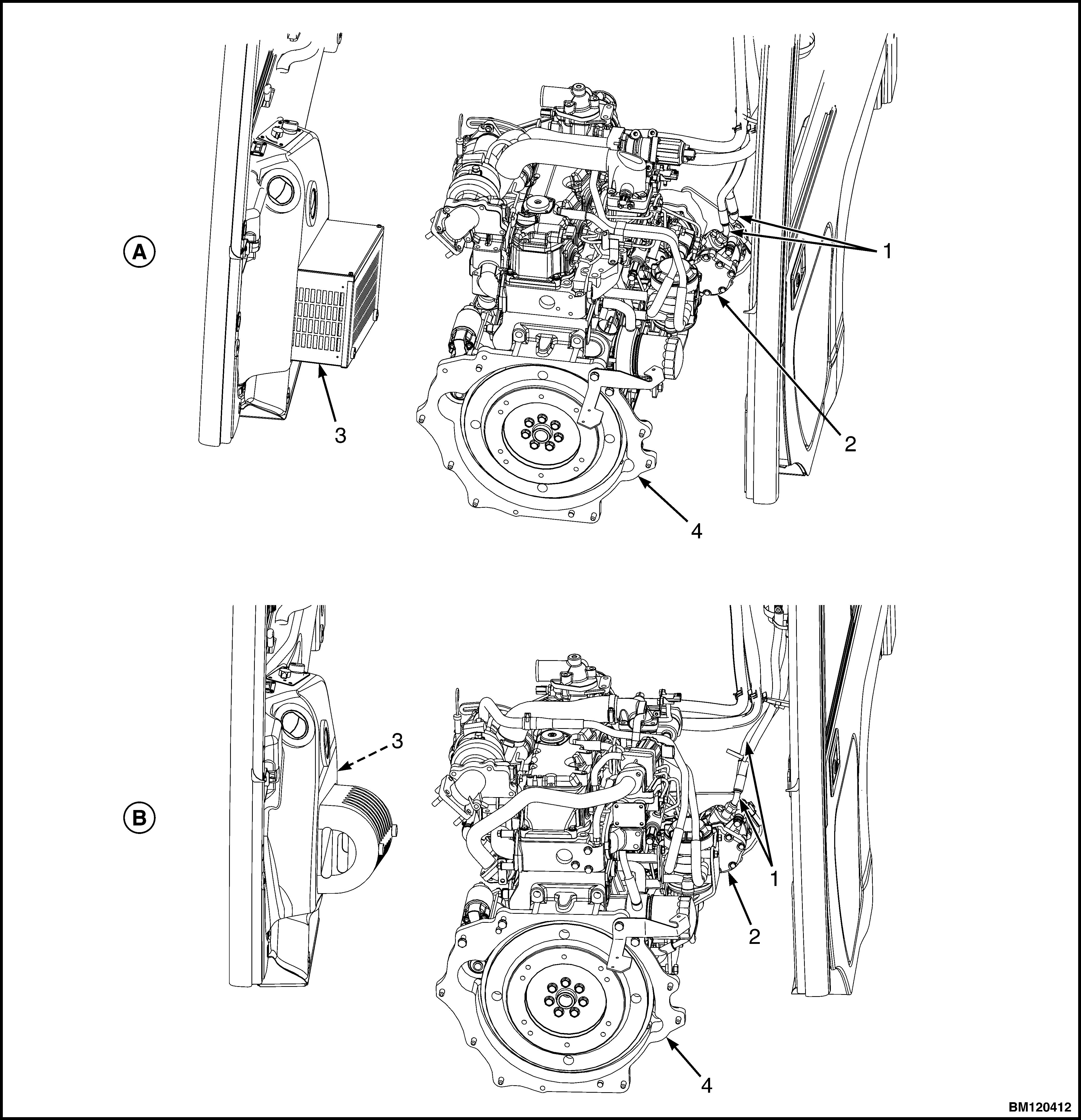
HEATER HOSES


Figure 6. Heater Hose Connection
Legend for Figure 6
Advertisement
NOTE: ART SHOWN MAY NOT REFLECT ENGINE IN LIFT TRUCK.
NOTE: MAJOR COMPONENTS OF CAB HAVE BEEN REMOVED FOR CLARITY.
A. LIFT TRUCK MODELS GLP/GDP16VX, GLP/
GDP18VX, GLP/GDP20SVX, GLP/GDP030VX (C810) B. LIFT TRUCK MODELS GLP/GDP20-35VX (GP/GLP/GDP040-070VX) (B875, C875) C. LIFT TRUCK MODELS GLP/GDP20-35VX (GP/GLP/GDP040-070VX) (B875, C875)
1. QUICK DISCONNECT FITTING 2. INNER REAR COVER 3. RADIATOR COVER D. LIFT TRUCK MODELS GLP/GDP40VX5/VX6;
GLP/GDP45SVX5, GLP/GDP45VX6; GLP/
GDP50-55VX (GP/GLP/GDP080, 090, 100, 110, 120VX) (F813, G813) E. LIFT TRUCK MODELS GLP/GDP40VX5/VX6;
GLP/GDP45SVX5, GLP/GDP45VX6; GLP/
GDP50-55VX (GP/GLP/GDP080, 090, 100, 110, 120VX) (H813, J813) 4. RIGHT SIDE DOOR ASSEMBLY 5. HEATER HOSES

NOTE: MAJOR COMPONENTS OF CAB HAVE BEEN REMOVED FOR CLARITY.
1. HOSE FITTING 2. REFRIGERANT COMPRESSOR 3. AC/HEATER UNIT 4. ENGINE
Figure 7. AC Refrigerant Hose Connections, Lift Truck Models GLP/GDP40VX5/VX6; GLP/GDP45SVX5, GLP/GDP45VX6; GLP/GDP50-55VX (GP/GLP/GDP080, 090, 100, 110, 120VX) (G813) with Cummins QSB 3.3L Engine
NOTE: MAJOR COMPONENTS OF CAB HAVE BEEN REMOVED FOR CLARITY. KUBOTA 3.8L DIESEL ENGINE SHOWN, 3.6L DIESEL ENGINE SIMILAR.
A. LIFT TRUCK MODELS GLP/GDP40VX5/VX6; GLP/GDP45SVX5, GLP/GDP45VX6; GLP/GDP50-55VX (GP/GLP/GDP080, 090, 100, 110, 120VX) (H813) B. LIFT TRUCK MODELS GLP/GDP40VX5/VX6; GLP/GDP45SVX5, GLP/GDP45VX6; GLP/GDP50-55VX (GP/GLP/GDP080, 090, 100, 110, 120VX) (J813) 1. HOSE FITTING 2. REFRIGERANT COMPRESSOR 3. AC/HEATER UNIT 4. ENGINE
Figure 8. AC Refrigerant Hose Connection, Lift Truck Models GLP/GDP40VX5/VX6; GLP/GDP45SVX5, GLP/GDP45VX6; GLP/GDP50-55VX (GP/GLP/GDP080, 090, 100, 110, 120VX) (H813, J813) with Kubota Diesel Engine
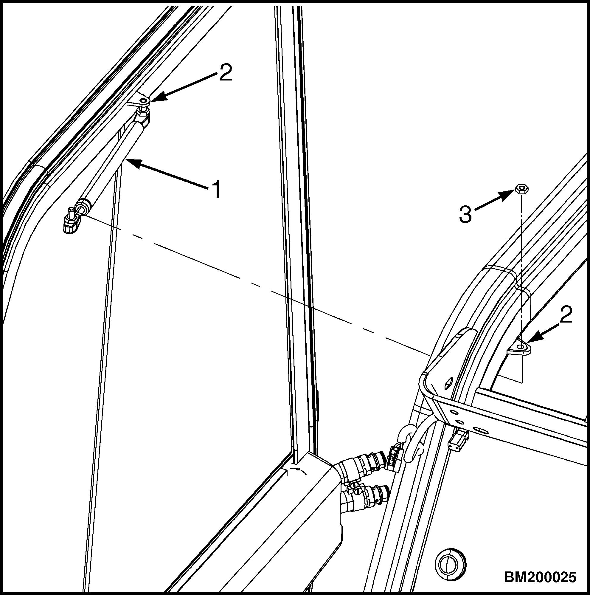
NOTE: RIGHT SIDE DOOR SHOWN.
1. GAS SPRING 2. CAB MOUNTING BRACKET 3. LOCK NUT
Figure 9. Gas Spring Mounting Removal

Figure 10. Door Removal Legend for Figure 10
NOTE: RIGHT SIDE DOOR HINGE SHOWN.
1. HINGE PIN 2. DOOR HINGE
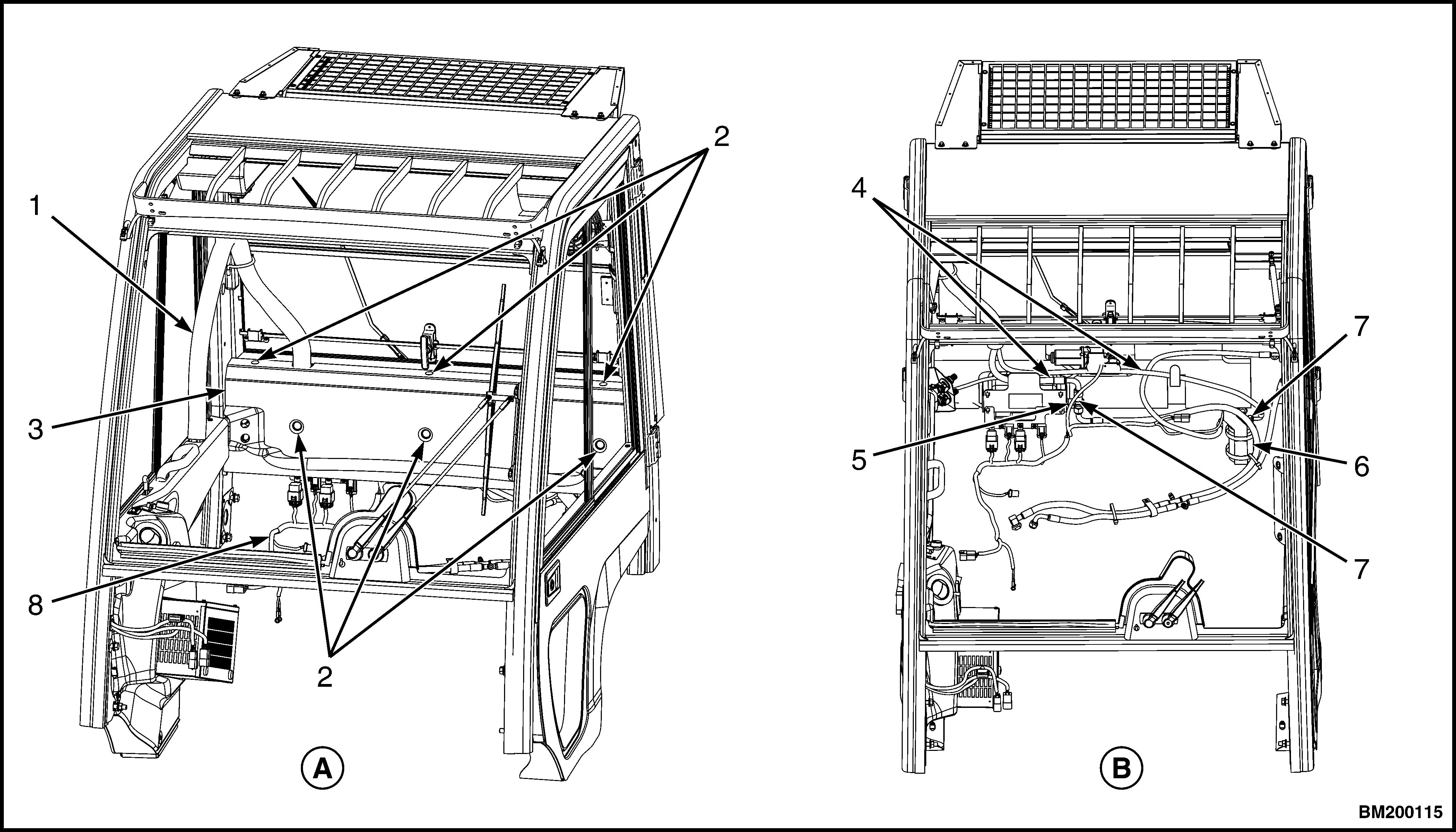
NOTE: MAJOR COMPONENTS OF CAB HAVE BEEN REMOVED FOR CLARITY.
1. HEATER WIRE HARNESS CONNECTOR 2. REAR GRAB HANDLE HORN BUTTON CON-
NECTOR (TO RIGHT-HAND CHASSIS HAR-
NESS)
Figure 11. Heater Wire Harness and Rear Grab Handle Horn Button Connectors

11. For lift truck models GLP/GDP40VX5/VX6; GLP/
GDP45SVX5, GLP/GDP45VX6; GLP/
GDP50-55VX (GP/GLP/GDP080, 090, 100, 110, 120VX) (G813, H813, J813) with a Cummins QSB 3.3L or Kubota diesel engine, if lift truck cab is equipped with an air conditioner/heater unit, disconnect AC hoses.
a. Remove six fasteners and remove rear cover.
See Figure 12 for lift truck models • GLP/GDP40VX5/VX6; GLP/GDP45SVX5, GLP/GDP45VX6; GLP/GDP50-55VX (GP/GLP/GDP080, 090, 100, 110, 120VX) (G813)
See Figure 13 for lift truck models • GLP/GDP40VX5/VX6; GLP/GDP45SVX5, GLP/GDP45VX6; GLP/GDP50-55VX (GP/GLP/GDP080, 090, 100, 110, 120VX) (H813)
See Figure 14 for lift truck models • GLP/GDP40VX5/VX6; GLP/GDP45SVX5, GLP/GDP45VX6; GLP/GDP50-55VX (GP/GLP/GDP080, 090, 100, 110, 120VX) (J813)
b. Disconnect air conditioner hoses at bulkhead bracket and at receiver/drier.
See Figure 12 for lift truck models • GLP/GDP40VX5/VX6; GLP/GDP45SVX5, GLP/GDP45VX6; GLP/GDP50-55VX (GP/GLP/GDP080, 090, 100, 110, 120VX) (G813)
See Figure 13 for lift truck models • GLP/GDP40VX5/VX6; GLP/GDP45SVX5, GLP/GDP45VX6; GLP/GDP50-55VX (GP/GLP/GDP080, 090, 100, 110, 120VX) (H813) See Figure 14 for lift truck models • GLP/GDP40VX5/VX6; GLP/GDP45SVX5, GLP/GDP45VX6; GLP/GDP50-55VX (GP/GLP/GDP080, 090, 100, 110, 120VX) (J813)
c. Disconnect air conditioner wire harness.
See Figure 12 for lift truck models • GLP/GDP40VX5/VX6; GLP/GDP45SVX5, GLP/GDP45VX6; GLP/GDP50-55VX (GP/GLP/GDP080, 090, 100, 110, 120VX) (G813)
See Figure 13 for lift truck models • GLP/GDP40VX5/VX6; GLP/GDP45SVX5, GLP/GDP45VX6; GLP/GDP50-55VX (GP/GLP/GDP080, 090, 100, 110, 120VX) (H813)
See Figure 14 for lift truck models • GLP/GDP40VX5/VX6; GLP/GDP45SVX5, GLP/GDP45VX6; GLP/GDP50-55VX (GP/GLP/GDP080, 090, 100, 110, 120VX) (J813)
12. Remove lock nut and disconnect gas spring from cab mounting bracket. See Figure 9.
13. Lift door up and over hinge pin and set aside. See
Figure 10.
NOTE: Wiper motor cover must be removed before dash assembly can be removed.
14. Unclip and remove front wiper motor cover. See
Figure 15 for lift truck models • GLP/GDP16VX, GLP/GDP18VX, GLP/ GDP20SVX, GLP/GDP030VX (C810) • GLP/GDP20-35VX (GP/GLP/ GDP040-070VX) (B875, C875)
NOTE: MAJOR COMPONENTS OF CAB HAVE BEEN REMOVED FOR CLARITY.
A. FRONT VIEW
1. HOSE WRAP 2. FASTENERS 3. REAR COVER 4. AIR CONDITIONER HOSES 5. BULKHEAD BRACKET 6. RECEIVER/DRIER 7. FITTINGS 8. AIR CONDITIONER WIRE HARNESS
B. TOP VIEW
Figure 12. AC System Arrangement and Hose Connections, Lift Truck Models GLP/GDP40VX5/VX6; GLP/ GDP45SVX5, GLP/GDP45VX6; GLP/GDP50-55VX (GP/GLP/GDP080, 090, 100, 110, 120VX) (G813) With a Cummins QSB 3.3L Diesel Engine
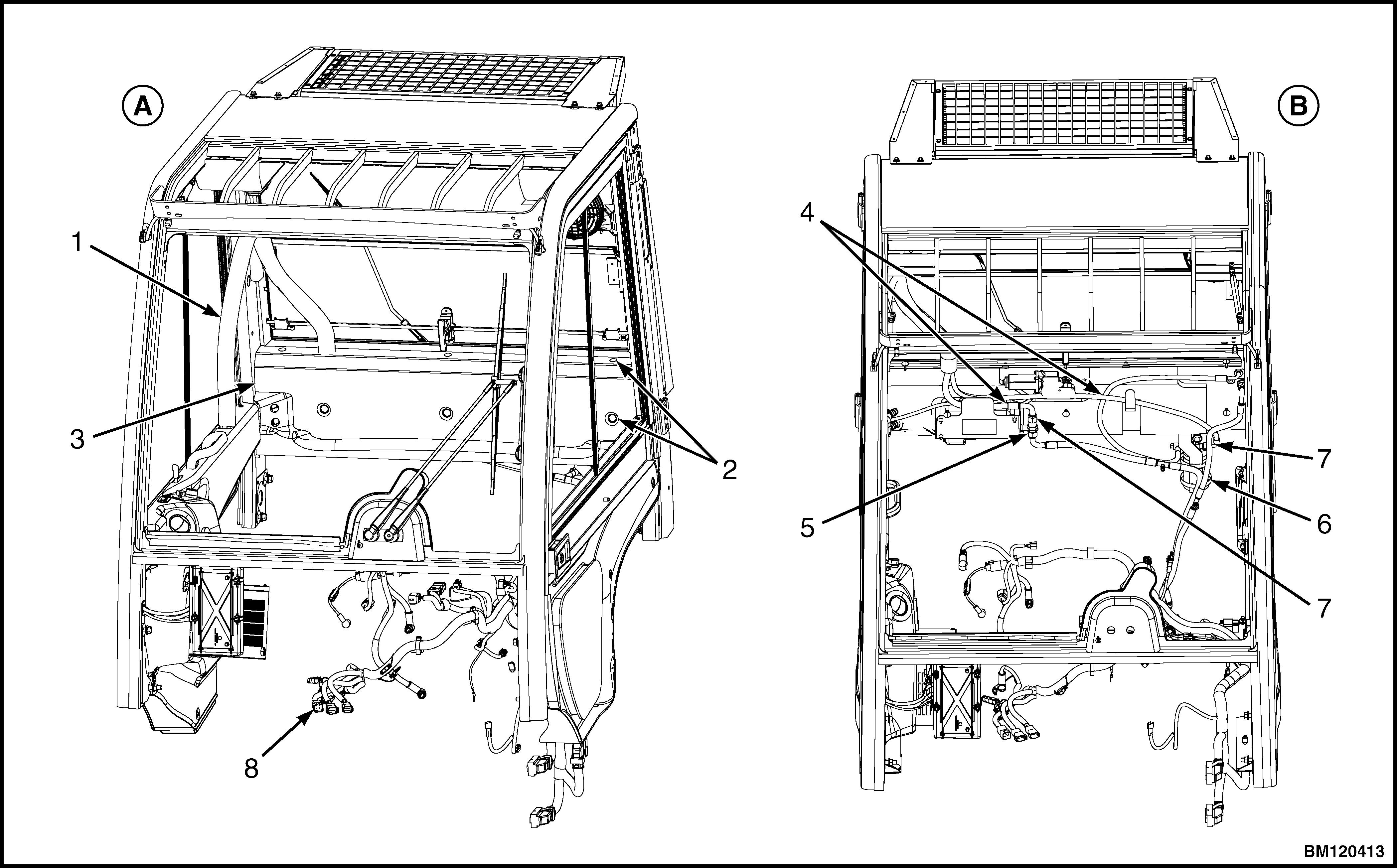
NOTE: MAJOR COMPONENTS OF CAB HAVE BEEN REMOVED FOR CLARITY.
A. FRONT VIEW
1. HOSE WRAP 2. FASTENERS 3. REAR COVER 4. AIR CONDITIONER HOSES 5. BULKHEAD BRACKET 6. RECEIVER/DRIER 7. FITTINGS 8. AIR CONDITIONER WIRE HARNESS
B. TOP VIEW
Figure 13. AC System Arrangement and Hose Connections, Lift Truck Models GLP/GDP40VX5/VX6; GLP/ GDP45SVX5, GLP/GDP45VX6; GLP/GDP50-55VX (GP/GLP/GDP080, 090, 100, 110, 120VX) (H813) With a Kubota Diesel Engine

NOTE: MAJOR COMPONENTS OF CAB HAVE BEEN REMOVED FOR CLARITY.
A. FRONT VIEW
1. HOSE WRAP 2. FASTENERS 3. REAR COVER 4. AIR CONDITIONER HOSES 5. BULKHEAD BRACKET 6. RECEIVER/DRIER 7. FITTINGS 8. AIR CONDITIONER WIRE HARNESS
B. TOP VIEW
Figure 14. AC System Arrangement and Hose Connections, Lift Truck Models GLP/GDP40VX5/VX6; GLP/ GDP45SVX5, GLP/GDP45VX6; GLP/GDP50-55VX (GP/GLP/GDP080, 090, 100, 110, 120VX) (J813) With a Kubota Diesel Engine

Figure 15. Dash Installation
Legend for Figure 15
NOTE: MAJOR COMPONENTS OF CAB HAVE BEEN REMOVED FOR CLARITY.
A. GLP/GDP16VX, GLP/GDP18VX, GLP/GDP20SVX (GP/GLP/GDP030VX, GP/GLP/GDP035VX, GP/GLP/
GDP040SVX) (C810) AND GLP/GDP20-35VX (GP/GLP/GDP040-070VX) (B875, C875) B. GLP/GDP40VX5/VX6; GLP/GDP45SVX5, GLP/GDP45VX6; GLP/GDP50-55VX (GP/GLP/GDP080, 090, 100, 110, 120VX) (F813, G813, H813, J813) 1. CAPSCREWS 2. FRONT WIPER MOTOR COVER 3. DASH ASSEMBLY 4. KICK PANEL 5. COWL PANEL 6. FRONT OPERATOR CAB LEGS 7. LOCK NUT 8. FLANGE BOLT
15. For lift truck models GLP/GDP40VX5/VX6; GLP/
GDP45SVX5, GLP/GDP45VX6; GLP/
GDP50-55VX (GP/GLP/GDP080, 090, 100, 110, 120VX) (F813, G813), remove two lock nuts from front wiper motor cover. Remove front wiper motor cover. See Figure 15.
16. For lift truck models GLP/GDP40VX5/VX6; GLP/
GDP45SVX5, GLP/GDP45VX6; GLP/
GDP50-55VX (GP/GLP/GDP080, 090, 100, 110, 120VX) (H813, J813), remove three lock nuts from front wiper motor cover. Remove front wiper motor cover. 17. Remove five capscrews from top of dash assembly and cowl panel.
18. Remove two flange bolts securing cowl panel to front operator cab legs.
19. Unclip dash assembly from kick panel. Remove dash assembly.
20. Remove kick panel from seal plate assembly. See
Figure 16.

Figure 16. Seal Plate Assembly, Kick Panel, and Floor Plate Removal
NOTE: CAB REMOVED FOR CLARITY.
Legend for Figure 16
A. GLP/GDP16VX, GLP/GDP18VX, GLP/
GDP20SVX, GLP/GDP030VX (C810) AND GLP/
GDP20-35VX (GP/GLP/GDP040-070VX) (B875,
C875) 1. CAPSCREWS 2. KICK PANEL 3. SEAL PLATE ASSEMBLY 4. SEAL B. GLP/GDP40VX5/VX6; GLP/GDP45SVX5, GLP/
GDP45VX6; GLP/GDP50-55VX (GP/GLP/
GDP080, 090, 100, 110, 120VX) (F813, G813,
H813, J813) 5. FLOOR PLATE (LEFT SIDE) 6. FLOOR PLATE (RIGHT SIDE) 7. FLOOR PLATE
21. Remove capscrews and seal plate assembly from lift truck frame.
22. Disconnect rear grab handle horn button connector from right-hand chassis harness, located in right rear corner leg of cab frame. See Figure 11.
23. Disconnect light harness connector from Vehicle
Systems Manager (VSM) and right-hand chassis harness connector. See Figure 17.
NOTE: Perform Step 24 and Step 25 for lift truck models GLP/GDP40VX5/VX6; GLP/GDP45SVX5, GLP/GDP45VX6; GLP/GDP50-55VX (GP/GLP/ GDP080, 090, 100, 110, 120VX) (J813) equipped with Diesel Particulate Filter (DPF).
24. Disconnect light harness connector from Vehicle
Systems Manager (VSM) and right-hand chassis harness connector. See Figure 18.
25. Disconnect Diesel Particulate Filter (DPF) display harness connector from cowl harness. See Figure 18.
26. Remove rear panels, front panels, and fender covers to access cab mounting capscrews and flange nuts. See Figure 19.
27. Remove front and rear cab capscrews and flange nuts from lift truck frame. See Figure 20. NOTE: KICK PANEL REMOVED FOR CLARITY.

1. VSM 2. LIGHT HARNESS CONNECTOR (TO VSM) 3. HARNESS CONNECTOR (TO RIGHT-HAND
CHASSIS HARNESS)
Figure 17. Light Harness Connection to Vehicle System Manager (VSM) for Lift Truck Models GLP/ GDP16VX, GLP/GDP18VX, GLP/GDP20SVX, GLP/
GDP030VX (C810), GLP/GDP20-35VX (GP/GLP/ GDP040-070VX) (B875, C875) and GLP/GDP40VX5/
VX6; GLP/GDP45SVX5, GLP/GDP45VX6; GLP/
GDP50-55VX (GP/GLP/GDP080, 090, 100, 110, 120VX) (F813, G813, H813)

NOTE: KICK PANEL REMOVED FOR CLARITY.
1. VSM 2. DPF DISPLAY HARNESS CONNECTOR (TO
COWL HARNESS) 3. LIGHT HARNESS CONNECTOR (TO VSM) 4. HARNESS CONNECTOR (TO RIGHT-HAND
CHASSIS HARNESS)
Figure 18. Electrical Harness Connection to
Vehicle System Manager (VSM) for Lift Truck
Models GLP/GDP40VX5/VX6; GLP/GDP45SVX5,
GLP/GDP45VX6; GLP/GDP50-55VX (GP/GLP/ GDP080, 090, 100, 110, 120VX) (J813)
NOTE: LEFT SIDE DOOR REMOVED FOR CLARITY.

1. REAR PANEL (LPG) 2. REAR PANEL (GAS AND DIESEL) 3. FRONT PANEL 4. FENDER COVER 5. SCREWS 6. CAPSCREWS
Figure 19. Front and Rear Panels and Fender Cover Removal

NOTE: ILLUSTRATION FOR REFERENCE PURPOSES ONLY. ACTUAL LIFT TRUCK MAY BE SLIGHTLY DIFFERENT.
A. FRONT VIEW B. REAR VIEW
1. CAPSCREWS 2. FLANGE NUTS
Figure 20. Front and Rear Cab Mounting WARNING
Make sure that the lifting device has a minimum capacity to lift 500 kg (1100 lb).
28. Connect a lifting device to a spreader bar or lift strap, that is through door openings at top of operator's cab (under overhead guard structure).
Place material that will be a cushion at top of door opening to prevent damage. Operate lifting device just enough to correctly position spreader bar or lifting strap on operator's cab. See Figure 21.
CAUTION
Lift the operator cab carefully. Check that all electrical wires and attachments are disconnected and are not damaged.
29. Carefully lift operator cab away from lift truck. Set operator cab in a storage area and place blocks under operator cab to make it stable and prevent damage to parts still attached.

Figure 21. Lift Strap Connection
INSTALL, FOR LIFT TRUCK MODELS GLP/GDP16VX, GLP/GDP18VX, GLP/ GDP20SVX, GLP/GDP030VX (C810); GLP/ GDP20-35VX (GP/GLP/GDP040-070VX) (B875, C875); AND GLP/GDP40VX5/VX6, GLP/GDP45SVX5, GLP/GDP45VX6, GLP/ GDP50-55VX (GP/GLP/GDP080, 090, 100, 110, 120VX) (F813, G813, H813, J813)
1. Connect a lifting device to a spreader bar or lift strap, that is through door openings at top of operator's cab (under overhead guard structure).
Place material that will be a cushion at top of door opening to prevent damage. Operate lifting device just enough to correctly position spreader bar or lifting strap on operator's cab. See Figure 21.
2. Carefully lift operator cab onto lift truck frame making sure that front and rear leg mounting holes are aligned with frame mounting holes.
3. Install capscrews and flange nuts to rear operator cab legs. Tighten capscrews to 66 N•m (49 lbf ft).
See Figure 20.
4. Install capscrews and lock nuts to front operator's cab legs. Tighten capscrews to 66 N•m (49 lbf ft).
5. Install fender covers, front panel, and rear panels to frame. See Figure 19. Tighten capscrews to 10.8 N•m (7.96 lbf ft).
6. Connect light harness connector to Vehicle Systems Manager (VSM) and right-hand chassis harness. See Figure 17.
NOTE: Perform Step 7 and Step 8 for lift truck models GLP/GDP40VX5/VX6; GLP/GDP45SVX5, GLP/ GDP45VX6; GLP/GDP50-55VX (GP/GLP/GDP080, 090, 100, 110, 120VX) (J813) equipped with Diesel Particulate Filter (DPF).
7. Connect light harness connector to Vehicle Systems Manager (VSM) and right-hand chassis harness. See Figure 18.
8. Connect Diesel Particulate Filter (DPF) harness connector to cowl harness. See Figure 18.
9. Connect right-hand chassis harness to rear grab handle horn button connector. See Figure 11.
10. Install seal plate assembly to lift truck frame and tighten capscrews. See Figure 16. 11. Install floor plate and floor mat. Tighten capscrews to 10.8 N•m (7.96 lbf ft).
12. Install kick panel onto seal plate assembly.
13. Install two flange bolts securing cowl to front operator cab legs. See Figure 15.
14. Install dash assembly onto kick panel and install five capscrews to secure dash assembly to cowl panel.
15. Install and clip front wiper motor cover for lift truck models • GLP/GDP16VX, GLP/GDP18VX, GLP/ GDP20SVX, GLP/GDP030VX (C810) • GLP/GDP20-35VX (GP/GLP/ GDP040-070VX) (B875, C875)
16. Install front wiper motor cover and tighten two lock nuts for lift truck models GLP/GDP40VX5/
VX6, GLP/GDP45SVX5, GLP/GDP45VX6, GLP/
GDP50-55VX (GP/GLP/GDP080, 090, 100, 110, 120VX) (F813, G813).
17. Install front wiper motor cover and tighten three lock nuts for lift truck models GLP/GDP40VX5/
VX6, GLP/GDP45SVX5, GLP/GDP45VX6, GLP/
GDP50-55VX (GP/GLP/GDP080, 090, 100, 110, 120VX) (H813, J813).
18. Install right side door onto cab by lifting door up and over top and bottom hinge pins. See Figure 10.
19. Connect gas spring and lock nut to cab mounting bracket. See Figure 9.
20. Connect heater hoses to heater assembly and connect heater wire harness connection. See Figure 6 and Figure 11.
21. For lift truck models GLP/GDP40VX5/VX6; GLP/
GDP45SVX5, GLP/GDP45VX6; GLP/
GDP50-55VX (GP/GLP/GDP080, 090, 100, 110, 120VX) (G813) with a Cummins QSB 3.3L engine and equipped with an air conditioner/heater unit, connect AC hoses. Tighten AC hose at bulkhead bracket to 29 to 37 N•m (21 to 27 lbf ft) and AC hose to receiver/drier to 15 to 18 N•m (133 to 159 lbf in). See Figure 12.


