1 minute read
Figure 8


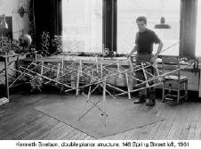
shown by accompanying drawings. In this way, he avoided the difficult task of giving a strict description. Perhaps Kenneth Snelson is clearer in his definition. In his patent, he describes: “The present invention relates to structural framework and more particularly, to a novel and improved structure of elongate members which are separately placed either in tension or in compression to form a lattice, the compression members being separated from each other and the tension members being interconnected to form a continuous tension network.” (1965, p.1) Some year later, Anthony Pugh gave the following definition of tensegrity, which was accepted by specialists, “A tensegrity system is established when a set of discontinuous compressive components interacts with a set of continuous tensile components to define a stable volume in space” (1976, p.3).
It was not until the 90s that Daniel L. Schodesk (1993) explain tensegrity as rigid structure made of discontinuous rods in compression and continuous cords in tension in which each component has one degree of member redundancy. Bin-Bing Wang, Li-Yan-Yun (1998,2003) went ahead with pervious definition, identifying other important characteristics: “Tensegrity systems are free-standing pin-jointed cable networks in which a connected system of cables is stressed against a disconnected system of struts and extensively, any free-standing pin-jointed cable networks composed of building units that satisfy aforesaid definition.” (pp. 93) There are further and more complex definitions depending on the perspective of the authors. Kanchanasaratool and Williamson (2002) state that a tensegrity system is a stable connection of axially-loaded members, being a Class k tensegrity structure if at most “k” compressive
Advertisement
Figure 8


