62 minute read
Using Advanced Sensors With VEX — Feel the Heat

from downmagaz
by Hiba Dweib

By Daniel Ramirez
Discuss this article in the SERVO Magazine forums at http://forum.servomagazine.com.
Advertisement
Remember the movie comedy “The Nutty Professor” — a Dr. Jekyll and Mr. Hyde comedy spoof starring Jerry Lewis and Stella Stevens that came out in the late ‘50s (see Figure 1)? Scenes from the movie showed beakers full of colorful mixtures bubbling up in Bunsen burners, and spinning centrifuges all working together. Just think how great it would have been for the nutty professor if he had the advantage of automatic timer controls.
FIGURE1. A still from the movie comedy "The Nutty Professor" — a Dr. Jekyll and Mr. Hyde spoof starring Jerry Lewis and Stella Stevens that came out in the late ‘50s.
Did you know that VEX Robotics kits could be used in chemistry or biology labs? With the timers, digital I/O, and analog I/O, we can control almost any kind of experiment that requires mixing at specific time intervals, temperature monitoring, or even measuring light levels. Using VEX components, we can make useful lab equipment such as motorized paddles to stir liquids or timers to control chemical processes. Instead of having to constantly watch an experiment, the VEX microcontroller can monitor it and record the data for you. Think of how much time you would save, so that you could move on to other experiments and learn so much more. In previous articles, we’ve talked about how to use the microcontroller to track the sun using astronomical equations. Now, it’s time to introduce the VEX microcontroller to the chemistry, physics, or even the biology lab.
The VEX microcontroller provides the timers and electronic control needed for your experiments. It rivals older electronic controllers that are far more costly. Individual VEX microcontrollers can be purchased used on eBay at a lower cost.
A VEX microcontroller has the following features that make it ideal for use in the lab:
• Built-in timers that can measure durations in microseconds to days. • Reacts very quickly to real time events triggering interrupts, using its internal timers. • Responds by using its PWM (pulse width modulation) outputs to control motors, servos, relays, or solenoids. • Can switch electronic devices connected to it on or off, depending on events or sensor readings using
the 16 digital I/Os. • Senses various physical properties including temperature, humidity, voltages, currents, light levels, sound levels, etc., using the 16 analog inputs (ADC).
In this article, we will experiment with analog temperature sensors. Temperature sensors include thermocouples, thermistors, and solid-state devices. Temperature sensors are associated with the sense of touch and/or feeling.
We use temperature sensors every day to monitor the indoor/outdoor temperature; for weather applications; commercial appliances, industrial applications, and scientific applications. In HVAC, thermostats control the room temperature by measuring the ambient room levels and comparing those to the set temperature. This way, the furnace activates when the temperature is below the set point. In automation, factory process control and robotics are used everywhere. Even your laptop or PC uses a sensor to monitor the CPU temperature. You can see then how important this sensor is to us.
Types of Analog Temperature Sensors
There are various types of analog temperature sensors, including lab glass thermometers; these include biological sensors such as our own nerve cells near the surface of the skin and electronic temperature sensors including analog and digital kinds. One of the early analog temperature sensors was developed in 1821, by the German-Estonian physicist Thomas Johann Seebeck who discovered that when any conductor is subjected to a thermal gradient, it will generate a voltage. This is known as the thermoelectric effect or Seebeck effect used in thermocouples.
Thermocouples have many commercial and research uses including process control and factory automation. These kinds of sensors can also be used for consumer and commercial high temperature applications such as ovens, furnaces, and stoves. For more information on the thermoelectric effect, see the article relating to it on Wikipedia (www.wikipedia.com).
Type K or type J thermocouples (shown in Figure 2A) are made by welding two wires of dissimilar metals together; they measure high temperatures and are accurate to within ±1 degree Celsius. They do require signal conditioning using op-amps and a Wheatstone bridge, since they generate a very weak voltage. This requires an op-amp to amplify the signal to a range that our microcontroller can read using the 10-bit ADC. Thermocouples measure the temperature difference between two points, not the absolute temperature. In order to measure a single temperature, one of the junctions — normally the cold one — is maintained at a known reference temperature; the other junction is at the temperature to be sensed.
Thermistors shown in Figure 2B are another type of analog temperature sensor similar to a resistor but whose resistance varies significantly with temperature. They are low-cost sensors that can be used for high temperature measurements. Although I was able to use them with the VEX microcontroller, I found them to not be as accurate as the LM34 temperature sensor shown in Figure 2C .They are not recommended for these experiments since they are not as accurate, and are much harder to use.
The low-cost LM34 Fahrenheit temperature sensor is a solid-state device with three wire leads that return the temperature readings in millivolts proportional to the current ambient temperature surrounding the sensor. For example, a temperature reading of 650 indicates a temperature of 65.0 degrees Fahrenheit. These analog readings are digitized using the microcontroller’s 10-bit analog-to-digital converter (ADC). LM34s are linear in nature and do not require calibration. Although they read temperature in degrees Fahrenheit to ±1 degree precision, SERVO 05.2012 57

FIGURE2A. A type K thermocouple used for scientific consumer and factory automation applications.
FIGURE2B. This is what thermistors look like. These are low-cost sensors but a bit more difficult to use due to their non-linear nature.
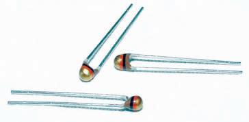
FIGURE2C.
The low-cost LM34 Fahrenheit temperature sensor is a solid-state device with three wire leads that return the temperature readings in millivolts proportional to the ambient temperature surrounding the sensor.
they can easily be converted to degrees Celsius. This sensor is perfect for VEX scientific explorations. Although it is not currently sold by Innovations First, Inc. (IFI), it can be found from other sources at a very low cost (check All Electronics at www.allelectronics.com).
Through some simple experiments, you can see how using the VEX microcontroller in the chemistry or biology lab can help in automating more complicated experiments that would normally be too time-consuming to carry out by hand, given a very heavy class schedule. This application could also be a good starting point for a science fair project in Chemistry or Biology. We’ll start by carrying out the temperature experiment described next which will show you how to use the LM34 with VEX.
Temperature Experiment: The Great Dead Sea Experiment
While it is rare to see temperature sensors used for VEX robotics applications, we see that this sensor is very important to our everyday lives (medical applications, heating, cooling, global warming, etc.). In chemistry, for example, a chemist can measure the temperature of various solutions and chemical reactions to monitor a particular experiment. Let’s learn more about chemistry ourselves by carrying out this experiment.
Setup is shown in Figure 3 and the necessary parts are listed in the Bill of Materials in Table 1. The LM34 (which will be immersed in a measuring cup) is protected from liquids and corrosive chemicals short-circuiting or corroding it by its coating of high temperature epoxy glue applied to the base of the sensor with the three wire leads. The mixing rod connected to the motor can also be protected in this manner.
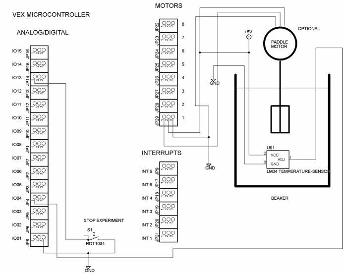
To carry out this experiment, we need to wire the circuit shown in the Figure 4 schematic. As you can see, the microcontroller and other VEX parts used here make it easy to carry out automated experiments. Interfacing analog temperature sensors to the microcontroller (such as the LM34) is a simple matter of connecting it to one of the 16 analog I/O pins or digital/analog I/O block using a three-pin .001 header or jumper wires, so that we can read it using one of the 10-bit analog-to-digital inputs; in this case, IO04. When building the circuit, make sure that you connect the correct power, ground, and signal wires to the LM34 as shown in the schematic. In order to reduce noise and get more accurate readings, we could connect up to 16 LM34 sensors and average the readings across all of the sensors.
To begin this experiment, fill a medium sized beaker or measuring cup with two cups (473 ml) of warm water at 122 degrees Fahrenheit or 50 degrees Celsius as measured from a calibrated lab thermometer from a sink faucet. Immerse the epoxy sealed LM34 into the measuring cup full of warm water and immediately run the Easy C application to start collecting readings to a text file using the text capture on the Easy C terminal. Run the Easy C application until the water temperature has dropped to room temperature. Verify these temperatures using a calibrated lab thermometer.
Next, we monitor the temperature of the water at 20 second intervals until the water reaches room temperature. Again, we collect this data using the Easy C debug window and save these results.Collect the data over a period of time until the water temperature has cooled to room temperature as measured by the lab thermometer.
TABLE1. Bill of Materials needed for our experiment.
ITEM QTY DESCRIPTION SOURCE
1 1 VEX microcontroller Innovation First, Inc. (IFI) www.vexforum.com 2 1 VEX 7.2 volt battery Innovation First, Inc. www.vexforum.com 3 1 Wire-wrap cable RadioShack www.radioshack.com 4 1 *VEX motor Innovation First, Inc. www.vexforum.com 5 1 *VEX pushbutton Innovation First, Inc. www.vexforum.com 6 1 Medium size VEX gear Innovation First, Inc. www.vexforum.com 7 1 LM34 temperature sensor All Electronics
www.allelectronics.com
8 1 Large glass beaker or measuring cup Local grocery store or chemistry lab
9 1 Salt (NaCl) Kitchen
10 1 Calibrated lab thermometer *Items are optional. Chemistry lab or local drug store
FIGURE3. The setup for our experiment is shown here. Note the temperature sensor; in this case, a solid-state LM34 connected to analogI/O pin IO04 in the digital/analog I/O block using a three-pin .001 header or jumper wires.

Figure4. This schematic shows how to connect the components needed for this experiment, including the LM32 temperature sensor and the optional stirring motor to the VEX microcontroller.
We will now repeat the same experiment described above, but dissolve one tablespoon of salt (or sodium chloride) in the warm water [H20 + NaCl]. Try to keep the starting and ending temperatures the same. Record temperature readings captured by the Easy C terminal to another file, since we will use both data files for analysis.
Finally, use the optional motor with a plastic gear or paddle attached (which is described next) to stir the pure water and salt water at 20 second intervals. Again, we use the microcontroller to monitor the temperature of the water at these 20 second intervals until the water reaches room temperature. Collect this data using the Easy C debug window and save the results.
Safety Warning: Use only warm
Figure5. The measuring cup, temperature sensor, and optional VEX motor used to stir the solution are shown here. Most of these components are available from the VEX kit or around the house.
water from the sink so as to avoid getting scalded. Wear goggles for this experiment. Place a splash guard over the measuring cup. Don’t boil the water on the stove to heat it; just use warm water from the faucet.

void main ( void ) {
long Resistance = 0; // Assuming a 10K Thermistor double Temperature = 0.0; // Scaled temperature reading in Degrees long Cycle = 0; // Number of cycles int Period = 0; // Measure temperature every n seconds int SetPoint = 75; // Set water temperature to 75 degrees double Sum_Temperature = 0.0; // Compute average temperature
Cycle=0 ; // Initialize the temperature reading cycle // count (every n seconds)
Sum_Temperature = 0.0 ; // Initialize the temperature sum
while ( 1 ) // Main control loop for temperature // experiment #1
// Read the temperature from the LM34 solid // state temperature sensor Temperature_Sensor_1 = GetAnalogInput ( LM34 ) ;
// Display the raw temperature sensor 1 // reading // PrintToScreen ( "Temperature 1 = %d\n" , // (int)Temperature_Sensor_1 ) ;
// Convert raw temperature to degrees // Fahrenheit Temperature = ConvertToFahrenheit (Temperature_Sensor_1) ;
// Accumulate the temperature sum for // 20 readings Sum_Temperature += Temperature ;
// Compute average temperature and display // every 20 Cycles
The Mixer Assembly
The optional mixer assembly shown in Figure 5 provides a means of stirring solutions at periodic intervals under control of the microcontroller. It is mounted on top of the beaker or measuring cup to prevent the liquid from splashing around. Most of the components used for this assembly are available from the VEX kit or from around your house. You may want to repeat the first experiment using the optional mixer to periodically stir the solution and see how it affects the liquid cooling rates.
The mixing motor is mounted centrally on a discarded CD or DVD by drilling two holes for the motor mount (refer to Figure 5 again). It is used as a splash guard to waterproof the motor. A chemical-resistant plastic paddle is attached to the motor axle and is used to stir chemical solutions at periodic time intervals as needed.
The mixing rod connected to the motor is coated with epoxy glue or plastic tubing to prevent it from exposure to corrosive chemicals; in this case, salt. A VEX three-wire motor is connected to the Motor 1 input on the motor block so that it can be switched on or off by the microcontroller at periodic intervals, as specified in the Easy C application. The motor activation periods are measured using the microcontroller’s internal timers, making it the perfect control timer. The optional pushbutton switch shown in the schematic can be used to start/stop the experiment.
PrintToScreen ( "Cycle = %d" , (int)Cycle/20 ) ;
// Compute the average temperature for // 20 cycles Temperature = Sum_Temperature / 20.0 ;
// Display the converted temperature // sensor 1 reading PrintToScreen ( " Temperature F = %ld" , (long)Temperature ) ;
// Convert temperature in degrees // Fahrenheit to degrees Celsius Temperature = ConvertToCelsius (Temperature) ;
// Display the converted temperature // sensor 1 reading PrintToScreen ( " Temperature C = %ld\n" , (long)Temperature ) ;
// Wait a bit between temperature // readings Wait ( 1000 ) ;
Sum_Temperature = 0.0 ; / // Initialize the temperature sum
// Increment the temperature reading cycle // count (every n seconds)
Cycle++ ;
Wait ( 50 ) ; // Wait a bit between temperature readings
LISTING1. This code demonstrates how you can read
the LM34 using the VEX microcontroller's ADC port. Remember it reads analog values and converts them to 10-bit digital values ranging from 0 to 1,023. It also shows you how to convert the digital values to specific temperatures in floating point in degrees Fahrenheit and Celsius, and shows you how to signal condition (filter) the LM34 using data collected from it at specific time intervals and then averaging them.
Data Collection
The temperature is read as a raw digital value between 0 and 1,023, representing the current analog temperature. So how do we scale these values to readings that we commonly use, such as degrees Fahrenheit or Celsius? The
Figure6. A plot of the cooling curve of warm water vs. the cooling curve of warm water with salt added to it. You can see for yourself what the effect of adding salt to water is and how it changes the heating/cooling characteristics.
answer to this question is the Easy C application used to collect the necessary temperature data shown in Listing 1. Data is captured to a text file using the Easy C terminal. Listing 1 provides answers to these questions. It also shows you how to convert the digital values to specific temperatures in floating point for degrees Fahrenheit and Celsius. Listing 1 shows you how to perform signal conditioning for the LM34 by using data collected from it at specific time intervals and averaging them. The Easy C source code is available with the article downloads.
The Easy C application Temperature_Experiment_1.c will collect the data for us and average every 20 readings per cycle in order to reduce noise in the temperature readings (this process is signal conditioning). Other techniques can be applied including using multiple temperature sensors, since up to 16 can be connected to the VEX microcontroller’s analog/digital inputs. In addition, using shielded wire such as microphone or coaxial video cable, or twisted pair wire can help to cancel out the electrical noise. Sometimes electronic RC filters are used on the analog inputs. Each temperature reading cycle takes 20 seconds to complete.
The period and number of samples taken before averaging can be easily modified in the Easy C application.
Data Analysis
After completing these experiments, we can plot the data using data analysis tools such as Microsoft Excel, Open Office Calc, Matlab, or even Open Octave (which is very similar to Matlab). Plot the cooling curve of warm water vs. the cooling curve of warm water with salt added to it as shown in Figure 6. It shows the plot of the cooling curve of warm water vs. the cooling curve of warm water with salt added to it so you can see the effect adding salt has and how it changes the heating/cooling characteristics. It also helps to explain why salt is added to water for cooking and is spread on roads during icy weather conditions.
Listing 1 demonstrates how you can read the LM34 using the microcontroller’s ADC port. Remember it reads analog values and converts them to 10-bit digital values ranging from 0 to 1,023. It also shows you how to convert the digital values to specific temperatures in floating point in degrees Fahrenheit and Celsius, and shows you how to signal condition (filter) the LM34 using data collected from it at specific time intervals and averaging them.
Applications
A VEX microcontroller on its own makes a great timer/intervalometer. Using the temperature sensor, we can control fans, heaters, and other types of equipment requiring thermal sensing. We can use it to heat or cool liquids for specific time periods or intervals depending on the experiment requirements. In fact, in photography, developing black and white or color film or slides requires a very accurate time and temperature process. These processes could be automated similar to the color labs at department stores or photography shops. The LM34 temperature sensor can also be used for weather or medical applications. For example, you can record the outdoor temperature over a period of days and plot it using the tools described in this article.
Conclusion
We discussed how analog temperature sensors work and what they can be used for. We showed how to use the LM34 analog temperature sensors with the VEX microcontroller by carrying out a simple experiment to measure liquid cooling rates with pure water, and then added sodium chloride to the water to see how it changed the heating/cooling properties. We also demonstrated how we can use VEX in the lab to help automate experiments. Next time, we will continue with analog temperature sensors and another temperature experiment. SV SERVO 05.2012 61

BASIC Atom Pro 28. By offloading the servo pulse generation and sequence movement timing to the SSC-32, the BASIC Atom has plenty of power.
The included Phoenix program allows the robot to walk with variable speed in any direction (translation), or turn in place (rotation), or any combination of the two. The leg lift and ride height is adjustable, as well as the gait walking speed. The body can rotate in every axis.
There are preset walking modes and gaits to choose from. All of these are accessible from the controller. Lynxmotion recommends the wireless PS2 controller (RC-01) to get the robot up and running quickly. The Phoenix code also supports a serial control mode for controlling the robot via a serial connection. The Phoenix code was written by Jeroen Janssen.
Programming is already done for the robot. The control options are: PS2 remote control; Xbee/DIY R/C stick radio control; and TTL serial control. The robot is compatible with the NiCad and Ni-MH Universal Smart Charger batteries and a 6.0 volt Ni-MH 2,800 mAh battery pack, both available from Lynxmotion.
For further information, please contact:
Lynxmotion
Website: www.lynxmotion.com
Is your product innovative,less expensive,more functional, or just plain cool? If you have a new product that you would like us to run in our New Products section,please email a short description (300-500 words) and a photo of your product to:
newproducts@servomagazine.com
Continued from page 29
DRIVE ME CRAZY

Robot cars are getting pretty good at parking themselves without crashing,or abducting their passengers.Robot cars also know how to drive like maniacs and even how to powerslide.These are all very neat tricks,but what's going to happen when all cars are this “talented?”
It's not just the sensor-driven skills that will soon be common to individual cars that will shape the future of automotive transportation, but also the ability for cars to communicate with each other,sharing constant updates about exactly where they are and where they're going.With enough detailed information being shared at a fast enough pace between all vehicles on the road,things like traffic lights will become completely redundant.
So,how close are we to something like this? It's hard to say.We have cars now that can drive themselves just about as reliably as a human can,and many automakers are working at inter-car communication.However,there are a lot of legal and social issues standing in the way of widespread adoption,and it's going to take a concerted effort to provide a framework in which we can safely allow progress to be achieved.
“The technology is pretty much already there,” says Peter Stone,a computer scientist at the University of Texas at Austin. Stone is thinking of the advantages for the disabled and elderly who can’t currently drive;for parents who don’t have time to take their kids to soccer (they can take themselves!);and above all,for traffic safety and the more efficient movement of people everywhere.It’s one thing,though,to realize that Google engineers have been zipping through our midst in autonomous concept cars. It’s another to picture what will happen when we’re all in these things – when the eye contact and social rules that currently govern urban driving are replaced by computer systems chatting with each other.“When they do interact,” Stone says,“it will be at intersections as much as anywhere else on the road.” Stone and one of his doctoral students,Kurt Dresner,realized intersections will change not just because they’ll need to accommodate driverless cars,but because driverless cars will make intersections much more efficient.Right now,you might wind up sitting at a red light for 45 seconds even though no one is passing through the green light in the opposite direction.You won’t have to do that in a world where traffic flows according to computer communication instead of the systems that have been built with human behavior in mind,however.


Attention Subscribers ask about your discount on prices marked with an *
CD-ROM SPECIALS


Robot Builder's Bonanza, Fourth Edition by Gordon McComb
Robot Builder’s Bonanza, Fourth Editionincludes stepby-step plans for a number of motorized platforms. The book is described as a compendium of robotics topics, containing more than 100 projects, including 10 robot designs new to the fourth edition. These modular robots are low cost, and are made to be reproduced by readers with no training in mechanical construction. $29.95*
ROBOTICS
In Making Things Move: DIY Mechanisms for Inventors, Hobbyists, and Artists, you'll learn how to successfully build moving mechanisms through non-technical explanations, examples, and do-it-yourself projects — from kinetic art installations to creative toys to energy-harvesting devices. Photographs, illustrations, screenshots, and images of 3D modelsare included for each project. $29.95*
Mechanisms and Mechanical
Devices Sourcebook 5th Edition by Neil Sclater N NE EW! W!
Fully revised throughout, this abundantly illustrated reference describes proven mechanisms and mechanical devices. Each illustration represents a design concept that can easily be recycled for use in new or modified mechanical, electromechanical, or mechatronic products. Tutorials on the basics of mechanisms and motion control systems introduce you to those subjects or act as a refresher. Reg $89.95 Sale Price $79.95
Build Your Own Humanoid Robots by Karl Williams
GREAT 'DROIDS, INDEED! This unique guide to sophisticated robotics projects brings humanoid robot construction home to the hobbyist. Written by a well-known figure in the robotics community, Build Your Own Humanoid Robots provides step-by-step directions for six exciting projects, each costing less than $300. Together, they form the essential ingredients for making your own humanoid robot. $24.95*
NEW RELEASE
O ONL NLY Y $39.95!* $39.95!*
Robot Programmer's Bonanza by John Blankenship,
Samuel Mishal
The first hands-on programming guide for today's robot hobbyist! Get ready to reach into your programming toolbox and control a robot like never before! Robot Programmer's Bonanzais the one-stop guide for everyone from robot novices to advanced hobbyists who are ready to go beyond just building robots and start programming them to perform useful tasks. $29.95
Robotics Demystified
by Edwin Wise YOU DON'T NEED ARTIFICIAL INTELLIGENCE TO LEARN ROBOTICS! Now anyone with an interest in robotics can gain a deeper understanding — without formal training, unlimited time, or a genius IQ. In Robotics Demystified, expert robot builder and author Edwin Wise provides an effective and totally painless way to learn about the technologies used to build robots! $19.95
We accept VISA, MC, AMEX, and DISCOVER Prices do not include shipping and may be subject to change.
SERVO Magazine Bundles
Save $10.00 Save $10.00 Onl Only $57.95! y $57.95!
Now you can get one year’s worth of all your favorite articles from SERVO Magazine in a convenient bundle of print copies.
Available for years 04, 05, 06, 07, 08, 09, 10 and 2011. RobotBASIC Projects For Beginners by John Blankenship,
Samuel Mishal
If you want to learn how to program, this is the book for you. Most texts on programming offer dry, boring examples that are difficult to follow. In this book, a wide variety of interesting and relevant subjects are explored using a problemsolving methodology that develops logical thinking skills while making learning fun. RobotBASIC is an easy-to-use computer language available for any Windowsbased PC and is used throughout the text. Price $14.95
LEGO MINDSTORMS NXT Idea Book by the Contributors to The NXT Step Blog
If you're serious about having fun with LEGO® robotics, you've come to the right place. The team behind The NXT STEP blog — the authoritative online source for MINDSTORMS® NXT information and advice — has packaged its considerable skills and experience in this book. Inside, you'll find some of the team's best ideas for creating cool and sophisticated models, including instructions for eight robots you can build yourself. Reg $29.95 Sale Price $24.95
Any bot builders out there? Get cool robotics stuff from my store! Call me at my order desk!
Visit m Visit my online stor y online store @ e @ www www.ser .ser vvomagazine omagazine.com .com
Linux Robotics by D. Jay Newman
If you want your robot to have more brains than microcontrollers can deliver —if you want a truly intelligent, high-capability robot — everything you need is right here. Linux Roboticsgives you stepby-step directions for “Zeppo,” a super-smart, single-boardpowered robot that can be built by any hobbyist. You also get complete instructions for incorporating Linux single boards into your own unique robotic designs. No programming experience is required. This book includes access to all the downloadable programs you need. $34.95
SPECIAL OFFERS CNC Machining Handbook: Building, Programming, and Implementation by Alan Overby
The CNC Machining Handbookdescribes the steps involved in building a CNC machine and successfully implementing it in a real world application. Helpful photos and illustrations are featured throughout. Whether you're a student, hobbyist, or business owner looking to move from a manual manufacturing process to the accuracy and repeatability of what CNC has to offer, you'll benefit from the in-depth information in this comprehensive resource. $34.95

Technology Education Package for Everyone Starting in Electronics This lab -- from the good people at GSS Tech Ed -- will show you 40 of the most simple and interesting experiments and lessons you have ever seen on a solderless circuit board. As you do each experiment, you learn how basic components work in a circuit. Along with the purchase of the lab, you will receive a special password to access the fantastic online interactive software to help you fully understand all the electronic principles.
For a complete product description and sample software, please visit our webstore.
Regular Price$99.95 Subscriber’s Price $95.95
SERVO 05.2012 65
Or order online www.servomagazine.com

SPECIAL OFFERS


The SERVO Buddy Kit
An inexpensive circuit you can build to control a servo without a microcontroller.
For more information, please check out the May 2008 issue or go to the SERVO webstore.
Includes an article reprint. Subscriber’s Price $39.55
Non-Subscriber’s Price $43.95 66 SERVO 05.2012
PROJECTS 3D LED Cube Kit
From the article “Build the 3D LED Matrix Cube” as seen in the August 2011 issue of Nuts & Volts Magazine.
This kit shows you how to build a really cool 3D cube with a 4 x 4 x 4 monochromatic LED matrix which has a total of 64 LEDs. The preprogrammed microcontroller that includes 29 patterns that will automatically play with a runtime of approximately 6-1/2 minutes. Colors available:Green,Red,Yellow & Blue. Jig and plastic cases also available.
Subscriber’s Price $57.95 Non-Subscriber’s Price $59.95 Forbidden LEGO by Ulrik Pilegaard / Mike Dooley Forbidden LEGOintroduces you to the type of free-style building that LEGO’s master builders do for fun in the back room. Using LEGO bricks in combination with common household materials (from rubber bands and glue to plastic spoons and ping-pong balls) along with some very unorthodox building techniques, you’ll learn to create working models that LEGO would never endorse. Reg $24.95 Sale Price $19.95

PS2 Servomotor Controller Kit
This kit accompanied with your own PlayStation controller will allow you to control up to six servomotors.
Includes all components and instruction manual. For more information,please see the February 2011 edition of SERVO Magazine. Assembled units available! Subscriber’s Price
$79.95
Non-Subscriber’s Price
$84.95

THIS MONTH: The Sensor Olympics 2 –Going the Distance

Discuss this article in the SERVO Magazine forums at http://forum.servomagazine.com
THE SCRIBBLERISLOOKINGTOTURNITS OPENINGVICTORYINTOAWINNINGSTREAK.
www.servomagazine.com/index.php?/magazine/article/may2012_TwinTweaks
Last time, we pitted some members of our robot menagerie against each other in a thrilling contest for infrared sensor supremacy. The slow and steady Scribbler came out on top with its enigmatic IR sensors, and the perennial competitor — the Mark III — is hungry for redemption this month. For the second event of the Sensor Olympics, we’ll be testing sensors used for obstacle avoidance – namely infrared rangefinders. Will the Scribbler extend its winning streak, or will the Mark III pull a surprise upset?
Open Rangefinder
Obstacle avoidance sensors are a popular feature for robot kits. A classic ingredient for a maze navigating bot, obstacle avoidance sensors generally work by sending out some sort of pulse, waiting for it to reflect off of an obstacle, and sensing the reflected pulse. The strength and delay of the reflected pulse give valuable clues as to the distance of an obstacle. The Scribbler and the Mark III both come with a classic solution for obstacle detection: infrared sensors. Both robots use a combination of infrared transmitters to send out a beam of infrared light and an infrared detector to sense the reflected beam. The Scribbler uses transmitters and detectors that are mounted in the very front of the bot, while the Mark III uses the extremely popular 2YOA21 Sharp rangefinders. Before we devised some tests for the sensors, we wanted to get a bit more acquainted with them.
The Scribbler obstacle avoidance sensors are a bit more accessible than the line following sensors, and can be reached simply by removing the Scribbler’s lid. Much like the line following sensors, the components themselves lacked any identifying information that might lead to a datasheet or other specifications. The official Scribbler information from Parallax is also less than illuminating – the Scribbler page describes the sensors as IR phototransistors, and the schematic does not indicate whether the sensors are implemented as digital or analog inputs. We wanted to know whether the sensors were used as digital or analog inputs because that would affect the way we
THE MARK III ISLOOKINGFORREDEMPTION.

THE SCRIBBLER'S IR SENSORSAREREADYTO STAREDOWNSOMEOBSTACLES.
A LOOKINSIDEREVEALSLITTLEABOUTTHEENIGMATICSENSORS. compared the Scribbler to the Mark III. Surely other tinkerers have had similar burning questions about the artistic bot, so the answers could likely be found on a robotics forum somewhere. However, we preferred to live by the sage mantra of Reading Rainbow’s LeVar Burton, so we wanted to see for ourselves instead of taking their word for it.
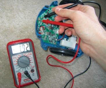
We pulled out our trusty multimeter to do a simple test that would determine if the sensors were analog or digital. We pressed the contacts against the ground and signal pins of the infrared receiver and moved an obstacle in front of the bot. If the multimeter gave a reading that jumped from zero volts to five volts once an obstacle got close enough, then it was treated like a digital input. If the multimeter gave a reading that gradually increased from zero to five volts as an obstacle approached, then the sensor was being used as an analog input. The results of our test were somewhat difficult to interpret given the difficulty in placing the contacts only on the individual legs of the infrared receiver, but we did only see dramatic jumps from zero to about five volts and no gradual change.
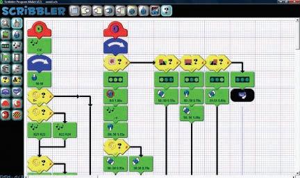
To seal the deal, we inspected the Scribbler program itself. The specialized Scribbler GUI — even with all of its colorful building blocks and images of brick walls that flagged the blocks dealing with obstacle avoidance — was about as forthcoming with technical details as Raj Koothrappali is with conversation around attractive women. Thankfully, the Scribbler program offers the option to see the code in Basic form, and that is where we found our definitive answer. The IR sensors were treated as either true or false — the hallmark of a digital input. Now that we had solved the mystery, the next question was what were we going to do with that prized knowledge.
A Sharper Image
One of the challenges in assessing the rangefinder sensors was to devise a test that would allow us to accurately track the results. Very often, rangefinding sensors are used for obstacle avoidance, usually in the context of a maze challenge. So when the sensor works, the robot doesn’t hit the obstacle. Sometimes when the sensor doesn’t work, the robot might miss the obstacle anyway out of pure luck or happenstance. So, what we needed was an obstacle directly in the path of the bot and a behavior that would unambiguously indicate sensing of the obstacle. For the Scribbler, this was an easy task. The LEDs could light up when an obstacle was sensed, and we could have the robot back up. A similar behavior could be programmed into the Mark III, minus the helpful LEDs.
The other challenge with devising a test was to determine a way to fairly compare the digital inputs on the Scribbler with the analog rangefinders on the Mark III. The Mark III uses two 2YOA21 Sharp rangefinders. The 2YOA21 sensors are the de facto successors to the


ubiquitous GP2D12 sensors, with comparatively improved range and reduced output fluctuations. The 2YOA21 sensors can sense obstacles in the range between 5 cm and 150 cm. The output voltage from the sensor can be converted into a range in centimeters using a simple calculation. The comprehensive datasheet for the sensor comes with all of this information and more, just as much a font of useful physics info and unsolicited trivia as Dr. Sheldon Cooper.
To compare this sophisticated sensor to the Scribbler’s more rudimentary array seemed like comparing apples to oranges. It seemed like a foregone conclusion that the 2YOA21 would have a better range, which was the intuitive metric for comparison. However, that very conflict inspired us as to what a useful comparison would be. The 2YOA21 was the type of top shelf sensor one might order specifically for a project, knowing that it will be up to snuff and super effective but the mysterious phototransistors in the Scribbler were more akin to the type of sensors that you might find buried in your toolbox –incidental discoveries when you are looking for something just good enough to get the job done.
It seemed like a useful question to have answered – can random toolbox sensors compete with cutting-edge improvements on popular designs? We wouldn’t necessarily look at range and other metrics often covered in datasheets, but rather we wanted to see how these sensors dealt with non-ideal conditions. Sure the Scribbler and Mark III can avoid bright walls well enough, but what about more ephemeral obstacles?
PROGRAMMINGTHE SCRIBBLERWITHANOBSTACLEAVOIDANCEPROGRAM.
PROGRAMMINGTHE MARK III WITHANOBSTACLEAVOIDANCEPROGRAM.
No Block on the Horizon
Before we moved on to more whimsical obstacles, we wanted to get a baseline for performance using a standard obstacle – something bright, something solid, something to bring relief on those sniffly days. A tissue box suited our purposes perfectly. To accurately track when our bots saw the obstacle, we marked distances in centimeters on the back of our line following track, and then we were ready to let the arch rivals duke it out once again. We started with the Scribbler. The LEDs and sudden backtracking made it obvious when the bot saw the box, and we marked off the distance over a number of trials. The Scribbler sensed the obstacle at distances ranging from 35 cm to 45 cm away, but showed a lot of variation within that range. The Scribbler did, however, always sense the obstacle and did not make the embarrassing gaffe of running headlong into the box.
TESTINGWITHOURSTANDARDOBSTACLE.
Up next was the Mark III. Even without LEDs, the robot’s sudden backtracking made it easy to note when it saw the obstacle. The Mark III also consistently spotted the obstacle, and it did so at a far more consistent distance than the Scribbler. Every trial resulted in the bot starting its moonwalk at about 34 to 35 cm. A little variation is to be expected. The motors aren’t perfectly calibrated, so the slightly different angle of approach could mean slightly different distances when the object is detected. This was a very pleasing result, however, given that the obstacle avoidance program we downloaded to the Mark III dictated that the bot take evasive maneuvers once an obstacle was 36 cm away. The discrepancy between the program and our measurements could be explained by the fact that our measurements used the front wedge of the Mark III as a guide while the rangefinders were set slightly back (about a centimeter) into the bot.
After our first round, it looked like the Mark III was ahead based on its excellent consistency. Now, we wanted to devise a test that would really separate the winners from the also-rans.

Once Upon a Time in the West
Much like with our light box last time, we wanted to test the sensor’s vulnerability to interference and non-ideal conditions. With the infrared sensors, we wanted to do something similar with our disappearing track but in a way that seemed more practically relevant to obstacle avoiders. Pondering what a problematic obstacle would look like conjured memories regarding a certain race through the desert in 2004.
It was a brisk March morning in Barstow, CA when a lumbering mechanical beast struck out on its ill-fated journey across the desert, doomed never to reach its destination at the gateway to the hedonist’s paradise in Primm, NV. The lumbering beast was TerraMax — the impressive entry from Big Truck Robotics. TerraMax was easily the biggest entry in the 2004 DARPA Grand Challenge, as it was based on a tactical military vehicle. The robot was outfitted with LIDAR and cameras for navigation, and when we first watched TerraMax at the qualifying races it exemplified the adage that slow and steady wins the race.
On race day, however, TerraMax’s dreams of greatness were stymied shortly into the race. After lumbering along for a little while, the massive bot stopped in its tracks. Had it gone off course and come face to face with an impassable ravine or massive boulder? Had some catastrophic mechanical failure crippled the behemoth to stop its inevitable march to the finish line? No, the reason for the robot’s stoppage was much smaller than that – a bush was in the way. A small, unsuspecting, prickly desert bush turned out to be the David that slayed the Goliath.
This was not because TerraMax was a die-hard environmentalist, but rather because the bot’s sensors
overestimated the solidity of the obstacle. Of course, the vehicle could trample a prickly bush without a second thought, but a boulder in the middle of the road was another matter entirely. If it was larger than the bot’s ground clearance, it could cause a major problem.
Fortunately, TerraMax returned in 2005 and completed the race but the experience in 2004 is illustrative of a real problem that obstacle avoidance sensors can have: They can overestimate the solidity and danger of ephemeral obstacles — things that could easily be gone through instead of around. An ephemeral obstacle would be a good way to test whether the IR sensors on the Scribbler and Mark III were sensitive, and perhaps overly so.
We didn’t have any tumbleweeds handy, so instead we repurposed some of our apartment décor. A peacock decoration with a feathery tail provided a perfect ephemeral obstacle – one that the Scribbler or Mark III could plow right through, but might prefer not to. We set up our testing ground and readied the Scribbler. After just a few tests, we were surprised at just how apparent the effects of changing the obstacle were. Before, the Scribbler sensed the tissue box at about 40 cm away. Now, however, the Scribbler was only taking evasive maneuvers at 10 cm if at all. Ambivalent as to whether this was a positive or a negative for the Scribbler’s sensors, we set about to test the Mark III.
A Force Majeure Interrupts the Sensor Olympics
We expected the Mark III to start its tests much like it did with the ephemeral obstacle – a steady approach followed by sudden backtracking when the obstacle was detected. This, however, is not what we saw. When we turned on the Mark III, it started moving backwards at a brisk pace. Afraid that perhaps a hand had been in front of a rangefinder when we activated the bot, we tried again. Again, the Mark III made a hurried retreat, and no amount of hand waving in front of the Sharp sensor would change its mind. We tried again, but this time the Mark III was spinning around in a counterclockwise motion. We weren’t playing dizzy bat, so we tried again, only to have the Mark III drive around in larger circles. Every new activation of the Mark III led to a random selection of these behaviors which struck us as extremely odd given that none of them really resembled the behavior we had programmed.
Our first instinct was to check the website for Savage Innovations, the creators of the OOPic. Unfortunately, the Savage Innovations website no longer exists, so support for the Mark III has become somewhat of an oral history of which this article may become a part. A quick bit of searching on the Internet led us to the proper diagnosis. Our Mark III exhibited the signs and symptoms of what has been termed by OOPic extraordinaire Richard Stofer as a “cosmic wedgie.” A
TESTINGWITHANEPHEMERALOBSTACLE.

ANTI-ECHOIC? cosmic wedgie occurs when the EEPROM doesn’t have enough time to reset at the beginning of a program. When this happens, the robot wanders off to never never land and engages in odd behaviors like we were seeing. Fortunately, there is an easy fix: All you need to do is reset the EEPROM.
This was an easier fix for us than it is for a lot of folks. All of the chips on our Mark III were socketed because it was always built as a platform for expansion. Some folks, however, insist on soldering the OOPic brain directly into the board. We personally think that sockets as a general policy are a good thing, but if the brain is directly soldered to the board it can be removed if you are a fan of desoldering. The whimsical novelty of solder suckers and solder braid wear off quickly though, and thankfully there is another solution for those that want to reset the EEPROM without having to remove the chip itself. The Mark III board includes two jumpers, and when the jumpers are shorted together before resetting the board and trying to download a new program, it will be treated the same as if you had removed the EEPROM. We tried both methods and they both worked like a charm.
Resetting the EEPROM, however, was only enough to bring the bot back from never never land temporarily. To keep the cosmic wedgie from becoming a chronic condition, we had to treat the cause. The cause, fortunately, is simple. The treatment for a cosmic wedgie is to give the OOPic enough time to reset at the beginning of the program. The consensus is that five seconds is sufficient, so one of the most important lines of code in an OOPic program is oopic.delay = 500 at the beginning of the program. The offending line in our program was easy to find, and it read oopic.delay = 50. Just as with the IRS or SEC, being one zero off is indeed a big deal. We added a zero, reprogrammed the bot, and finally resumed the Sensor Olympics.
We like to include these experiences because we think dealing with unexpected problems is a part of the process experienced by all tinkerers. Working with a kit is never as smooth as following the step-by-step instructions. There will always be things left unmentioned by the manual; there will always be unexpected speed bumps on the road to your completed project.
Once we were able to test the Mark III with our ephemeral obstacle, we were surprised that once again it gave a result markedly different from the Scribbler. The Mark III consistently spotted the obstacle from a distance of 36 cm and evaded it accordingly. On one hand, this was an impressive result for the Mark III. The sensors were sensitive enough so that they even spotted our feathery simulacrum of the bush that foiled TerraMax. On the other hand, too much sensitivity to ephemeral obstacles could leave the bot feeling trapped when, in fact, it could plow obliviously through like the Scribbler.
We decided that the Mark III’s result was the better


Infinitely Modifiable.e.


Extraordinarily Durable. All-Terrain Robotics.


one. There are numerous ways to compensate for oversensitivity. The program could average a few readings to sort of gauge the solidity of an obstacle. Presumably, an ephemeral obstacle will inconsistently reflect the IR beams leading to a low average, while a solid obstacle will consistently reflect the beams. Also, an array of sensors would be able to provide more information, and that may be one reason why the Mark III did indeed see the obstacle – it is outfitted with two of the Sharp rangefinders.
Closing Ceremonies
After our ephemeral obstacle, we had grand plans for a third challenge based on our anticipation of receiving a third type of sensor to test – the SRF05 from Devantech, an ultrasonic rangefinder that we would equip to the Mark III. Unfortunately, Devantech seems to be the Matt Damon to our Jimmy Kimmel Live, and we just ran out of time because the sensor didn’t arrive. We have heard nothing but good things about Devantech from other tinkerers, but we always seem to have bad luck. In any event, stay on the lookout for a future project involving the SRF05. We still tested the Scribbler with our rendition of an anti-echoic obstacle meant to stymie an ultrasonic sensor, but both bots had no problem avoiding that obstacle as easily as the tissue box.
Our goal with the Sensor Olympics is fairly straightforward: to gain an intuitive understanding of the advantages and disadvantages of different types of sensors. Sure, many sensors have nicely detailed datasheets, but many of these stats about peak voltage and power consumption don’t necessarily reveal whether this sensor will work to get you through that maze. Datasheets often don’t reveal how the sensor will react to non-ideal conditions. This, however, is an understandable limitation because it would be foolish to expect concise datasheets to comprehensively list all of the ways in which conditions can stray from the ideal.
Of course, many times intrepid tinkerers are left without the guidance of datasheets. Sometimes, you’ll be rummaging through your toolbox or cannibalizing old kits for parts, and the sensors you find may not have the identifying marks necessary to lead you to a datasheet. In that case, it is very useful to know how sensitive sensors are to different situations. Are most sensors dramatically affected by the reflectivity of the obstacles? Or, will most sensors be good enough to get my robot through the labyrinth safely?
In the end, we had no reservations about declaring the Mark III the winner of this event. The 2YOA21 Sharp rangefinders are impressive sensors that proved to us why they are, in fact, the standard in many kits. The Scribbler’s simple IR phototransistors were a bit more flummoxed by changes in obstacle type, but it still gave a respectable effort that would be enough to get it through most mazes. SV
Then and NOW
Discuss this article in the SERVO Magazineforums at http://forum.servomagazine.com
Sensors For Mobile Robots
b y T o m C a r r o l l
That is exactly the title of Bart Everett’s great sensor book from 1995, shown in Figure 1. Well, it’s no coincidence because Bart’s book has literally been a ‘bible’ for me in robot writing and consulting, as well as for thousands of other experimental robot builders. Bart is a friend of mine and works in one of the most enviable positions for a robotics enthusiast at the Navy’s SPAWAR Systems Center in San Diego, CA. I have visited the site on several occasions and have seen some of the most amazing robot creations you could imagine.
In his book, Bart starts out discussing robots that he built as a kid, starting with Walter back in 1965. Bart’s teleoperated anthropomorphic robot met its untimely demise when the household cleaning lady went into young Bart’s bedroom (he was a sophomore in high school at the time) and turned on an old vacuum cleaner that emitted so much electromagnetic static that the five foot tall radiocontrolled robot went berserk. When he came home and saw his decapitated robot on the floor, the dented vacuum cleaner on its side still running, and the front screen door off its hinges, it was obvious that the maid had ‘killed it’ with one mighty swing of the vacuum and left in such a hurry as to never be seen again.
Walter had no onboard sensors for perceiving its physical surroundings. Its successor was Crawler I — a small tracked robot equipped with tactile feelers made from looped guitar strings, and barely enough onboard intelligence to support a very primitive bump-and-recover mobility behavior. Non-contact sensing had to wait for Everett’s first computer-controlled robot — ROBART I — which was his thesis project at the Naval Postgraduate School in the early 1980s. This robot utilized two types of sensors. One was an active ranging system based on the National Semiconductor LM-1812 monolithic sonar transceiver chip used in underwater fish finders and the other was a modified near-infrared proximity sensor from surplus circuit boards used on toys. ROBART I also had considerable collision detection capability in the form of an extensive array of tactile sensors, along with over-current sensing for its tandem drive motors.
The big sensing breakthrough on ROBART II came in 1982 with the introduction of Polaroid’s ultrasonic ranging system which employed a novel electrostatic transducer specifically designed for operation in air; the original application, of course, being automatic camera focusing. The LM-1812 compatible transducers were designed for underwater use and had trouble achieving an effective impedance match with air. Thanks to the high-volume camera application, the Polaroid system was both small and inexpensive which allowed a total of 36 of these sensors to ultimately be incorporated on ROBART II (Figure 2). These were augmented with a number of improved near-infrared
FIGURE 1. Sensors for Mobile Robots by Bart Everett. FIGURE 2. Bart Everett's Robart II.
proximity sensors for enhanced collision avoidance.
According to Everett, “The basic idea was synergistic fusion of two different inexpensive sensor modalities to increase the chances of target detection and improve the accuracy. The slow speed of sound facilitates time-of-flight range measurements, but the associated beam divergence makes for poor angular resolution. Optical energy is easy to focus into a tight beam, but the speed of light is much harder to measure over short ranges.”
Everett’s long-time friend Anita Flynn — then an MIT coop student working for the Navy — wrote her Master’s thesis on this concept using ROBART II’s sonar and optical sensors to collect empirical data for a variety of target sources.
Sensors Have Unlimited Applications
Sensors are part of almost every electro-mechanical device, whether industrial or commercial devices for the home. Robots — as mechanical devices that move — need all sorts of sensors, especially mobile robots. For those with interests in the more technical aspects of sensors, the NASA Tech Briefs SENSORS Tech Forum this October in Anaheim, CA is just one of many conferences dealing with sensors.
Simple toy robots may not have sensors, but they certainly could use sensors to allow them to detect a wall and make a turn, rather than continually trying to go through it. An edge-detecting sensor might help a simple robot from rolling off a table top and smashing itself on the floor. iRobot certainly was aware that they would have to place a lot of sensors in their Roomba vacuuming robot to allow it to perform even the simplest of room cleaning tasks. The Roomba has both of the sensor types mentioned above, and many more.
Active IR sensors detect wall proximity and slow the robot down or cause it to turn. An edge-detecting sensor allows it to see a dangerous top of the stairs and causes it to back and turn before it can perform a dive to its death. I wrote about robot sensors five years ago in SERVO but many new types have been developed since then. This time, I’d like to concentrate on sensors that detect objects and barriers, and as a result of this detection, are motion controlled. We’ll concentrate on just active and passive object locator sensors.
Switches are the Earliest Examples of Robot Obstacle Detection
In the early days of robotics and for more simple robots these days, the use of bumper switches and whiskers to detect objects is a simple solution. My first robot (eons ago) used two four-pole double-throw switches — one at each end of the robot to change the polarity of the motors, thus changing the direction of the robot. All it could do was bang back and forth when it hit a wall in the front or back. That seemed stupid to me, so I changed things a bit with four separate double-pole double-throw (DPDT) switches — one at each corner with a bumper. A curved bumper around the front part of the robot’s base had a single DPDT switch behind it that would trigger when that part of the bumper was depressed. That really screwed up the works because the robot would sometimes spin out of control, so I tried a stepping relay, then a small bank of logic relays, and so on.
Later, I added a set of small coat-hanger wire whiskers attached to the front of the robot that could detect an object if one of the whiskers was moved. Rather than using sensitive micro-switches attached to each of the whiskers, I found it easier to have a conductive whisker surrounded by a circular ring contact surface so that any motion of the whisker up/down or right/left would cause the whisker to contact the circular ring and trigger a circuit. The Parallax Boe-Bot uses a similar set of whiskers mounted in front of two sets of conductive pins as shown in Figure 3. These early examples of sensors worked, but other builders and I found many better ways for our robots to detect and respond to the outside world.
FIGURE 3. Parallax Boe-Bot whisker arrangement.
Detecting Obstacles Away From the Robot
It is nice for your robot to be able to detect an object or obstacle before it slams into it or even gently touches it. There are many types of sensors that can accomplish this detection, with the most popular two being active ultrasonic and active infrared. The word ‘active’ implies that the sensor sends out a signal and then receives a returned echo. Detection before contact allows the robot to easily make a course change, or at least slow down (like the Roomba). Non-contact detection also prevents scaring or nicking of walls, molding, furniture, and objects. There are still a few marks on the lower moldings in my house where SERVO 05.2012 75
my first Roomba slammed into them a bit too hard.

Ultrasonic Object Detection and Ranging
Let’s examine some different distance measuring transducers. Consumer ultrasonic systems have been around for decades, such as intrusion alarms and early TV remote controls. These intrusion systems were adapted by some robot experimenters for object detection since many used simple time delay measurements for determining distance. Doppler frequency shift techniques can be used for speed sensing when an object is drawing closer; the returning signal’s frequency shifts higher with shorter wavelengths, and vice versa on moving away. When Polaroid came out with their series of autofocus cameras (mentioned earlier) that used a single electrostatic transducer, robot builders and hackers were just waiting to tear into them and use them for robot detection methods. Polaroid has since gone through difficult financial times. The company has been shredded and one small company is trying to supply the instant film portion while another — FIGURE 4. Polaroid sensor SensComp — purchased the OEM development kit. products division of Polaroid and has expanded its line of electrostatic and piezoelectric technologies. The electrostatic type of transducer requires a bit more circuitry to complete the overall system but has much longer distance measuring capability of six inches to 35 feet. I still have four of the original Polaroid development kits from the ‘80s, one of which is shown in Figure 4. The original angled camera circuit board has the transducer attached, and the large development board has a three-digit LED display for the distance readout. The black Polapulse battery holder was for the six volt battery developed especially by Polaroid; it’s a flat, high current battery that was inside each pack of instant film. When I received these, I immediately inserted one of the supplied batteries and turned the system on. Holding the transducer in my hand, I was aiming it around my room when I accidentally touched the back of the transducer and was zapped by 300 volts. One only does that once. SensComp now makes an excellent sonar unit (shown in Figure 5) based on the original Polaroid design. It’s available at AcronameRobotics. It combines the 600 series transducer and a SensComp 6500 series ranging module. The system costs $56 and is Acroname part number R14-SONAR1. If you need the extended range for your robot design, I highly recommend this sonar. It has a very narrow beam width of 15º with a drop of 6 dB which is great for distancing smaller objects. As you might know, these active sonar systems use the delay of an ultra-high frequency sound (ultrasonic) pulse that travels at the speed of sound at 1,126 feet per second, or 768 mph to and from the target object. The further away, the longer the delay. The SensComp 6500 operates on 4.5V to 6.8V at 100 mA current draw. I found out that it works just fine on five and six volts with a crude bench setup I used. I could get reliable return reflected signals at 30 or more degrees from a painted wall. The system has 80 mS recycle cycles with FIGURE 5. SensComp R14 sonar 16- 49.4 kHz bursts. It’s larger and more expensive than thefrom Acroname. smaller two-transducer units but has much greater range.FIGURE 6. Parallax Ping))) with Gadget Gangster The Acroname site (acroname.com/robotics) has a link to cyperbolic reflector. the code and hookup of the sensor system to a BrainStem microcontroller (“Data Logging with a BrainStem GP 1.0”); links to other controllers can be found on search engines.
Piezoelectric Distance-Ranging Transducers
The more popular piezoelectric transducers are sold by many companies and robot suppliers. These types of sensors emit an ultrasonic frequency sound burst in the


FIGURE 7. Ping))) reflector performance.
range of 40 to 42 kHz that travels to the target and is reflected back into either the same transducer that sent the pulse or into another transducer. In the same manner as the electrostatic system, a microcontroller measures the elapsed time from the time that the pulse is sent until it is received, and converts it to a digital representation of the distance measured.
The Parallax Ping)))
One of the more popular ultrasonic distance sensors used by many robot experimenters is the Ping))) by Parallax (shown attached to an optional Gadget Gangster $15 cyperbolic reflector in Figure 6). The ultrasonic distance sensor’s sensitivity performance with and without the reflector is shown in Figure 7. Ultrasonic sensing cannot be compared with visual sighting because a 3.5” diameter cylinder does not reflect anywhere the same amount of sound waves back to the sensor as would a 3.5” square/flat object at the same distance, whereas the two objects would appear about the same to a video system. Soft objects as well as slanted surfaces also reflect a much attenuated signal. The sensor provides an output pulse to the robot’s microcontroller at the time the sensor sends the 40 kHz, 200 µS pulse that will terminate when the return echo is received and the time differential is calculated to determine the distance.
Parallax Ping))) specifications include: • Supply Voltage – 5 VDC • Supply Current – 30 mA typical; 35 mA max • Range – 2 cm to 3 m (0.8 in to 10 ft) • Input Trigger – Positive TTL pulse, 2 µS min, 5 µS typical • Echo Pulse – Positive TTL pulse, 115 µS to 18.5 mS • Echo Hold-off – 750 µS from fall of trigger pulse • Burst Frequency – 40 kHz for 200 µS pulse • Burst Indicator LED shows sensor activity • Delay before next measurement – 200 µS • Size – 22 mm H x 46 mm W x 16 mm
Single-Transducer Range Finders
extensive line that is very appropriate for people detection, remote monitoring, industrial applications, as well as mobile robotics. With over 30 different sensors in their arsenal, I have selected and tested just a few that I feel are great for entry to mid-level mobile robot platforms.
The MB7060 shown in Figure 8 is a weatherproof unit that is intended for outdoor use. I found it actually works in the rain. The only time that the unit began to not work was when I was out in the rain and tried facing it upwards to detect the bottom of my upper deck. This was because the cone started to fill with water and distorted the pattern.
This would be a great robot transducer for RoboMagellan robots that can operate in foul weather. With a 42 kHz output and a fairly narrow beam width, it has a resolution of 1 cm and has a range of 25 feet. Operating on 3.0V to 5.5V @ 3.4 mA, the output into a BASIC Stamp or Arduino microcontroller can be a straight analog voltage, serial output, or a pulse width measurement. The mounting is a typical 3/4” NP thread.

FIGURE 8. MaxBotix MB-7060 WR1 sonar.
FIGURE 9. MaxBotix MB 1200 and 1240 sonar.
FIGURE 10. MaxBotix MB1010 EZ-1 sonar. FIGURE 11. Devantech SRF01 ultrasonic range finder from RobotShop. FIGURE 12. Dagu compound IR sensor from RobotShop.


The MB1200 shown in Figure 9 is a wide beam, indoor sensor with similar characteristics to the 7060, and would make a great sensor for a mobile robot that needs a broad pattern for people and object detection. The wide beam is quite adept at detecting small targets, such as the plastic ruler stuck in my grass at 20 feet away. It is a very small sensor mounted on a 7/8” x 3/4” board; it’s 5/8” long and would be great on a very small robot, as well as a larger FIRST-type build.
The MB1240 is virtually identical to the 1200, but has the narrowest beam of any MaxBotix sensor and seems to work the best with a larger, hard target. The MB1010 EZ-1 shown in Figure 10 is their most popular indoor sensor, and the least expensive at $29.95. It is appropriate for any indoor robot. It has a lower operating voltage range of 2.55.5V @ 2.0 mA. The MaxBotix site has detailed specs and links for more information.
RobotShop — the large Canadian robot hobbyist supply company — has a large selection of robot sensors. Their popular British-made Devantech SRF01 ultrasonic range finder shown in Figure 11 can be calibrated to measure from zero distance to almost 20 feet. Operating from 3.3 to 12 volts @ 11 to 25 mA, the 5/8” dia by 3/4” long transducer is a perfect match for smaller robots that need a bit of measurement range. A rubber mounting grommet is also supplied. At $35.99 US, the 2.7 gram unit communicates on a single pin serial output at 9600 baud.
RobotShop also has a unique IR sensor called the Dagu compound infrared sensor shown in Figure 12. Designed to be with their Dagu Mr. General robot kit, the $9 US board is a series of four IR LEDs, each paired with two focused IR transistors. The sensor board can be mounted on a $14.99 US pan & tilt mount; the kit (shown in Figure 13) is for use on any small robot.
Another popular IR range finder is the GP2YOA710YK module made by Sharp and handled by Acroname for $19.50. With a range of three to 18 feet operating on 4.5V to 5.5V @ 33 to 50 mA, the sensor shown in Figure 14 includes a connector kit and has been a perfect match for
FIGURE 14. Sharp GP2Y0A710YK IR sensor from Acroname.
FIGURE 15. Tiangulation method used with IR sensors.


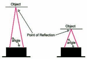
FIGURE 13. Dagu mini pan & tilt kit from RobotShop.
FIGURE 16. Parallax laser range finder. FIGURE 17. Parallax LRF camera cube structure.
many small robot platforms. Figure 15 shows a sketch of the triangulation method this and most IR range finders use. Very complete information can be found at “Demystifying the Sharp IR Rangers” on the Acroname site.

Parallax Laser Range Finder
Many of us have longingly looked at the Hokuyoand SICK laser range finders and wish that we could shovel out $1,200 to over $5,000 for one of these quality units. They’ve adorned the fronts of DARPA Grand Challenge vehicles, as well as top-of-the-line industrial robots. Some builders have taken the laser range finders that hunters or golfers use and have converted them for robot use. However, Parallax — in conjunction with Grand Idea Studio — has produced an affordable $129.99 laser range finder that is made to use on robots. Shown in Figure 16, the 3.95” x 1.55” x 0.67” module operates off of 5.0V @ 150 mA. Communication is by an asynchronous serial 300115,200 baud output.
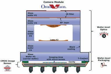
The Arima laser on the right in Figure 16 is tiny enough, but the tiny object with the red dot on the left is a full VGA camera that detects the projected red 635 nm (visible) red laser dot’s position angle to determine distance by triangulation. Note in Figure 15 how the dot’s position appears at a greater angle at a closer range for the Sharp linear array. The difference here is that the camera and laser are 78 mmapart, and the detector is a VGA camera rather than a linear array (as in the Sharp sensor). Figure 17 shows the inner structure of the tiny 1/13” camera with two filters and two lenses. Check out the Parallax, GrandIdea Studio, and OmniVision sites for some very interesting information, and also the October and November ‘11 issues of SERVO in which Joe Grand (President of Grand Idea Studio) wrote a complete description of the board.


Final Thoughts

I have covered only a small portion of the many sensors used just for object detection and range finding for robots. I will cover compass, location, and robot positional sensors in next month’s column. I would like to thank my friend Bart Everett, Technical Director for Robotics at the SPAWAR Systems Center, for help with my intro about him and his friendship. Personnel at Parallax, MaxBotix,theRobotShop, andAcroname have been most helpful in assisting me with their products and specific information. It is companies like these (and others) that allow us to build the robots of our dreams. SV
FREE Stencil
with every prototype order
EAGLE order button
pcb-pool.com/download-button on your first order 20% off!
Call Tyler: 1 707 447 7744 sales@pcb-pool.us
PCB-POOL® is a registered trademark of Tom Carroll can be reached at TWCarroll@aol.com. www.pcb-pool.com