AIR-ANT2535SDW-R Datasheet
Overview
2.4 GHz 3dBi/5 GHz 5dBi Low Profile Antenna, White, RP-TNC
Quick Specification
Product Code
AIR-ANT2535SDW-R
Enclosure Color
White
Antenna Type
Omnidirectional
Operational Frequency Ranges
2.4-2.5 GHz & 5.15-5.925 GHz
Nominal Input Impedance*
50 Ohms
Diameter
1.25 in. (3.18 cm)
Height
3.3 in. (8.4 cm)
Weight
1.7 oz. (0.05 kg)
Product Details:
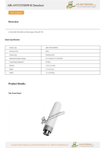
The Front Panel:
Copyright © 2022 Hi-Network.com | HAILIAN TECHNOLOGY CO., LIMITED | All Rights Reserved.
AIR-ANT2535SDW-R Datasheet System Requirements
This antenna is designed for use with Cisco access points having dual-band antenna ports. These include the Cisco Aironet 1600, 2600, 3600, 3700, and Cisco Catalyst 9120AXE series access points. The antenna is intended solely for indoor deployments. The Self Identifying Antenna model AIR-ANT2535SDW-RS= is supported only on Cisco Catalyst 9800 Series Wireless Controllers running an IOS-XE 17.4.1 release or a later release. This antenna model is not supported on Cisco AireOS Wireless Controllers.
Safety Precautions
For your safety, read and follow these safety precautions: 1. Before you install an antenna, contact your Cisco account representative to explain which mounting method to use for the size and type of antenna that you are about to install. 2. Find someone to help you—installing an antenna is often a two-person job. 3. Select your installation site with safety, as well as performance, in mind. Remember that electric power lines and phone line s look alike. For your safety, assume that any overhead line can kill you. 4. Contact your electric power company. Tell them your plans and ask them to come look at your proposed installation. 5. Plan your installation carefully and completely before you begin. Each person involved in an installation should be assigned to a specific task and should know what to do and when to do it. One person should be in charge of the operation to issue instructions and watch for signs of trouble. 6. When installing your antenna, follow these guidelines: a. Do not use a metal ladder. b. Do not work on a wet or windy day. c. Do dress properly—wear shoes with rubber soles and heels, rubber gloves, and a long-sleeved shirt or jacket. 7. If the assembly starts to drop, move away from it and let it fall. Because the antenna, mast, cable, and metal guy wires are all excellent conductors of electrical current, even the slightest touch of any of these parts to a power line completes an electrical path through the antenna and the insta ller. 8. If any part of the antenna system should come in contact with a power line, do not touch it or try to remove it yourself. Call your local power company to have it removed safely. 9. If an accident should occur with the power lines, call for qualified emergency help immediately.
Installation Notes The antenna is designed to connect to a dedicated antenna connector on the access point. No special tools are required to install the antenna.
Choosing a Mounting Location
The antenna radiates an omnidirectional pattern in the plane of the access point. To achieve this pattern, the access point should be mounted clear of any obstructions to the sides of the radiating element. If the mounting location is on the side of a building or tower, the antenna pattern is degrad ed on the building or tower side.
Copyright © 2022 Hi-Network.com | HAILIAN TECHNOLOGY CO., LIMITED | All Rights Reserved.
AIR-ANT2535SDW-R Datasheet Tools and Equipment Required
No tools are required to mount the antenna to the access point. For information about tools required to mount the access point, see the appropriate access point documentation.
Mounting the Antenna
To connect the antenna to the access point, follow these steps: Step 1 Align the antenna’s RP-TNC connector with the appropriate antenna port. Step 2 Gently push the antenna into the port. Step 3 Hand tighten the antenna to the port using the metal knurled ring only. Warning: Do not use the plastic body to tighten. This may damage the antenna.
Get more information: Do you have any question about the AIR-ANT2535SDW-R? Contact us now via e-mail: info@hi-network.com
Specific Data Sheet: Antenna Type
Omnidirectional
Operational Frequency Ranges
2.4-2.5 GHz & 5.15-5.925 GHz
Nominal Input Impedance*
50 Ohms
VSWR*
2.0:1
Polarization
Vertical
2.4 - 2.5 GHz Nominal Peak Gain*
3 dBi
5.15 - 5.925 GHz Nominal Peak Gain*
5 dBi
2.4 - 2.5 GHz Elevation Plane Beamwidth*
35°
5.15 - 5.925 GHz Elevation Plane Beamwidth*
35°
2.4 - 2.5 GHz Port-to-Port Isolation*
> 20 dB
5.15 - 5.925 GHz Port-to-Port Isolation*
> 23 dB
Connector Type
Male RP-TNC
UV Stability
ASTM D-4674 Method 1
Diameter
1.25 in. (3.18 cm)
Height
3.3 in. (8.4 cm)
Weight
1.7 oz. (0.05 kg)
Operating Temperature Range
-30° C to 70° C
Storage Temperature Range
-40° C to 85° C
Copyright © 2022 Hi-Network.com | HAILIAN TECHNOLOGY CO., LIMITED | All Rights Reserved.
AIR-ANT2535SDW-R Datasheet *When the antenna is mounted to a Cisco Aironet 1600, 2600, 3600, 3700, or Cisco Catalyst 9120AXE access points.
Want to Buy
Learn More about Hi-Network
Search our Resource Library
Follow us on LinkedIn
Contact HI-NETWORK.COM For Global Fast Shipping
HongKong Office Tel: +00852-66181601 HangZhou Office Tel: +0086-571-86729517 Email: info@hi-network.com Skype: echo.hinetwork WhatsApp Business: +8618057156223
Copyright © 2022 Hi-Network.com | HAILIAN TECHNOLOGY CO., LIMITED | All Rights Reserved.
Contact for Sales or Support