AIR-ANT24120 Datasheet
Overview
2.4 GHz,12 dBi Omni Mast Mt. Antenna w/RP-TNC Connector
Quick Specification
Antenna type
Vertical colinear array, Omnidirectional
Operating frequency range
2400-2500 MHz
Nominal input impedance
50 Ohms
Dimensions
42 x 1.5 in (106 x 3.8 cm)
Weight
3 lb (1.36 kg)
Connector type
RP-TNC plug
Peak gain
12 dBi
Product Details:
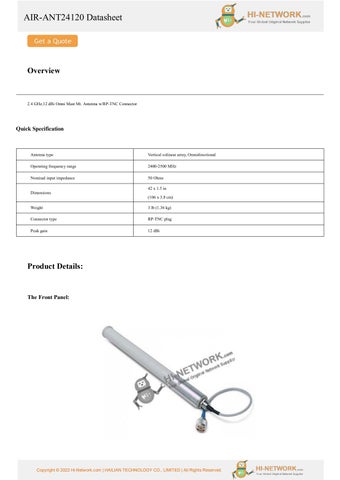
The Front Panel:
Copyright © 2022 Hi-Network.com | HAILIAN TECHNOLOGY CO., LIMITED | All Rights Reserved.
AIR-ANT24120 Datasheet E-Plane Pattern
H-Plane Pattern
System Requirements This antenna is designed for use with Cisco Aironet access points and bridges but can be used with any 2.4-GHz Cisco Aironet radio device that uses a reverse-polarity threaded naval connector (RP-TNC).
Installing Notes
Choosing a Mounting Location
The antenna is designed to create an omni-directional broadcast pattern. To achieve this pattern, the antenna should be mounted clear of any obstructions to the sides of the radiating element. If the mounting location is on the side of a building or tower, the antenna pattern will be blocked on the building or tower side.
Tools and Equipment Required
To install the antenna, you will need the following tools and equipment. • A 7/16 in. (11 mm) open end or combination wrench • A 1/2 in. (13 mm) open end or combination wrench The following sections contain procedures for installing the antenna. Choose the procedure that applies to your situation. Use Figure 1 as a guide.
Copyright © 2022 Hi-Network.com | HAILIAN TECHNOLOGY CO., LIMITED | All Rights Reserved.
AIR-ANT24120 Datasheet Mounting the Antenna
The antenna is provided with a mounting kit. This kit allows you to mount the antenna to masts up to three inches in diameter. The antenna is vertically polarized. Since the antenna has vertical gain, it is very important to mount the antenna in a vertical (not leaning) position for optimal performance. Follow these steps to mount the antenna to a mast. Step 1 Position the sandcast bracket on the mast. Step 2 Secure the sandcast bracket to the mast using two 5/16-18 U-bolts, split lock washers, and hex nuts. Step 3 Use a 1/2 in. (13 mm) wrench to tighten each hex nut to full compression of the split lock washers. Step 4 Slide the antenna in the sandcast bracket and align it so that the 1/4-20 hex bolts fit into the grooves on the antenna base. Step 5 Use a 7/16 in. (11 mm) wrench to tighten the hex bolts until they secure the antenna to the sandcast bracket. Do not overtighten. Step 6 Use a 7/16 in. (11 mm) wrench to tighten the 1/4-20 jam nuts. Do not overtighten. Step 7 Connect the antenna's pigtail coaxial cable to the transmission line.
Suggested Cable Specifications for Cisco Aironet Low-Loss Antenna Cable Feature
AIR-CAB020LL-R
AIR-CAB050LL-R
AIR-CAB100ULL-R
AOR-CAB150ULL-R
Cable length
20 ft (6 m)
50 ft (15 m)
100 ft (30 m)
150 ft (46 m)
Transmission loss
1.3 dB
3.4 dB
4.4 dB
6.6 dB
Get more information: Do you have any question about the AIR-ANT24120? Contact us now via e-mail: info@hi-network.com
Specific Data Sheet: Antenna type
Vertical colinear array, Omnidirectional
Operating frequency range
2400-2500 MHz
Nominal input impedance
50 ohms
Nominal VSWR
1.5:1
Peak gain
12 dBi
Polarization
Linear, vertical
Dimensions
42 x 1.5 in (106 x 3.8 cm)
Weight
3 lb (1.36 kg)
Connector type
RP-TNC plug
Coax type
RG-213
Environment
Outdoor
Copyright © 2022 Hi-Network.com | HAILIAN TECHNOLOGY CO., LIMITED | All Rights Reserved.
AIR-ANT24120 Datasheet Operating temperature range Wind rating
-40oF to 158oF (-40oC to 70oC) 125 mph (201 kmh)
Want to Buy
Learn More about Hi-Network
Search our Resource Library
Follow us on LinkedIn
Contact HI-NETWORK.COM For Global Fast Shipping
HongKong Office Tel: +00852-66181601 HangZhou Office Tel: +0086-571-86729517 Email: info@hi-network.com Skype: echo.hinetwork WhatsApp Business: +8618057156223
Copyright © 2022 Hi-Network.com | HAILIAN TECHNOLOGY CO., LIMITED | All Rights Reserved.
Contact for Sales or Support