57 minute read
HYDRAULIC EXCAVATOR MAINTENANCE MANUAL

First Edition of January 2013
To users
Dear users, thank you for choosing Zoomlion hydraulic excavator. Before maintain this machine, please read and fully understand this manual and strictly comply with the relevant provisions in it.
Regular inspection, maintenance and repair on the machines are the essential means to ensure that the machines can give full play to their excellent performance, work safely and reliably and have their service lives prolonged. In order to make it convenient for you to do inspection, maintenance and repair for the machines, we provide this Maintenance Manual for you.
The maintenance manual gives you a detailed introduction on the rules and explanations about the inspection, maintenance and repair of hydraulic excavators and also introduces methods of troubleshooting for the common faults.
In order to make the machines work normally and to ensure you and other people’s personal safety, make sure that you have read up on the manual and other attached documents carefully and thoroughly before maintaining and repairing the machines. If you have any doubts or questions, please contact the local service engineers and we will provide technical support for you timely and effectively. The company will not bear any undesirable consequences resulted in disobeying the rules of this maintenance manual.
In the process of maintaining the machines, any person without authorization cannot dismantle or adjust the hydraulic components. When any hydraulic components are broken down or any parts are damaged, please call our local service engineers.
Because of the constant improvement and upgrades of product design as well as differences in the product specifications and models, the details of some pictures and text content in the manual may be a little different from the products that you possess. The company reserves the right to revise the content of this Maintenance Manual due to technical improvement. We are subject to change without prior notice and we hope that all users can understand us.
This maintenance manual is suitable forZE205E/ZE230E hydraulic excavators.
Thank you very much for your trust and support for Zoomlion products. We sincerely wish you all the best!
Safety Instructions
The manual involves the following safety and warning icons:
Danger
High risk of danger: there is risk of death or heavy injuries.
Warnings
Middle risk of danger: there is risk of heavy injuries.
Attention
Slight risk of danger: there is risk of light injuries or moderate injuries.
CautionCaution
Safety sign: there is risk of property loss.
Prompt
This icon marks instructions for particular information.
Importance
The icon is for showing the importance of particular information.
It shows that this operation does not conform to the safety specification and easily causes death and injuries, so it is forbidden.
Chapter One: Safety Criterion for Excavator
Chapter One: Safety Criterion for Excavator Maintenance
1.1 Basic Safety Requirements for Maintenance
It is of great significance to carry out maintenance and repair for the excavators, for this can extend the machines’ service lives, ensure the personnel and machines’ safety, improve work efficiency and increase economic benefits. Except reading the "Safety Tips", maintenance staff should comply with the following regulations: a) The staff in charge of maintenance should not perform the maintenance work unless they have fully understand the structure, performance, assembly and disassembly procedures, technical requirements and precautions of the complete vehicle. b). For difficult maintenance items, you'd better consult the manufacturer. c). Routine maintenance is usually carried out before starting the vehicle and after completing the work every day. Park the vehicle on level ground, lock the locking mechanism, and then carry out maintenance. d). Before maintenance, the surrounding area of the parts to be maintained should be cleaned and scrubbed thoroughly, especially the surrounding area of oil filling port, filter, fuel injectors and box cover, so as to prevent dust from entering into the oil. e). Always remember that there is high pressure in the hydraulic circuit and release the pressure first before refueling, fuel discharging or inspection and maintenance. f). Before changing engine oil, start the vehicle and let the oil temperature rise to 30℃~40℃ before draining the old oil. g). Use clean oil and grease. The inspection or change of oil should not be performed at dusty place, otherwise the dust will enter into the oil. h). The electrical system can not be handled in the rain. i). When checking or adding coolant, take care not to let the hot water spray out and hurt people. j). After the replacement of engine oil filter element or coarse strainer, air in the oil circuit should be discharged. k). It is prohibited to refuel with the filter screen on the oil filling port being removed. l). Before overhauling the gearbox, empty the pockets. Take care not to let wrenches, nuts and other things fall into the cabinets, resulting in unnecessary troubles. m). Keep oil far away from fire and do not use a torch instead of lighting. n). When replacing O-rings, gaskets or other seals, the parts surface should be cleaned and installed carefully.
1.2 Precautions for Maintenance
Carry out technical maintenance correctly and timely, that is, perform such technical maintenance works as inspection, cleaning, lubrication, adjustment and fastening etc. for the machines frequently and regularly. This will not only increase the production efficiency, reduce wear and avoid unexpected failures, but also improve excavators’working efficiency, extend machines’service lives and reduce maintenance costs.
The machine’s maintenance period is recorded by the hour meter. Under poor operating conditions, maintenance should be done earlier than the required time.
Attention
1. Comply with relevant provisions of the "Safety Operation Specification" during maintenance.
2. When maintenance is performed under the vehicle, put up signs at the driver's seat or around the vehicle when necessary.
3. Before cleaning or refueling the machine, checking the tension of the fan belt or inspecting the moving parts and their nearby parts, shut down the engine.
4. Before maintaining, inspecting or charging the batteries, shut down the engine and remove the battery clips at the same time. Before dismantling the connector between the batteries and the charger, switch off the charger switch.
5. Keep away from open fire during maintenance (no smoking and no electrical sparks).
6. Before carrying out oil feeding, oil draining or other inspections and maintenance for the hydraulic system, release the pressure first.
7. Special adjusting tools should be used when adjusting oil pressure, or else failures will occur when performing difficult maintenance items.
8. During inspection and maintenance, only essential personnel can approach.
9. All oil filling ports, surface of oil dipstick and all fuel containers should be kept clean; only oil of brands specified by Zoomlion should be used; the inspection and replacement of various oils should be performed in environments with few dusts, so as to maintain high degree of cleanliness.
ZE205E/ZE230E HYDRAULIC EXCAVATOR
Maintenance Manual
Chapter Two: General Drawing and Main Parameters of Excavator
Chapter Two: Outline and Main Parameters of Excavator
2.1 Outline of Excavator
The appearances of hydraulic excavators ZE205E/ZE230E introduced in this manual are generally the same, as seen in Figure 2-1.
2.2 Main Technical Parameters of Excavator
See Table 2-1 for the main technical parameters of ZE205E/ZE230E hydraulic excavators, Figure 2-2 for the outline dimension and Figure 2-3 and Figure 2-4 for the working range
Table 2-1
Main technical parameters of ZE205E/ZE230E hydraulic excavators


ZE205E/ZE230E
Hydraulic Excavator Maintenance Manual
Chapter Three: Maintenance of Excavator
Chapter Three: Maintenance of Excavator
3.1 Maintenance Information of Excavator
When operating or steering the machines, users must carry out regular maintenance and repair work for them, so as to guarantee safety. In addition, to further improve safety, users should also replace the key parts regularly, because the materials of these parts will change as time passes by and these parts are prone to wear down or deteriorate. Since it is hard to determine the conditions of parts through regular maintenance, you should change the parts when the prescribed time for replacement arrives, which is essential to guarantee that these parts are in good condition all the time. These parts are closely related to safety and fire prevention.
If these parts are abnormal before the replacement cycle arrives, they must be repaired or changed instantly. Please contact Zoomlion or Zoomlion dealers to replace the key safety parts. Before maintaining and repairing excavators, please read the “Operation Manual” and the following maintenance guidelines first.
Prompt
1. Don’t carry out any inspection and maintenance not described in this manual.
2. Maintenance and repairs should be done on flat and firm ground.
3.1.1. Hour Meter’s Readings
Check the readings of the hour meter every day and see whether they have arrived the required time to carry out maintenance.
3.1.2. Genuine Wearing Parts of Zoomlion
Use the genuine parts of Zoomlion specified in the “Parts Catalogue” for replacement.
3.1.3. Lubricating Oil
Use the engine oil and lubricating oil designated by Zoomlion. Choose the engine oil and lubricating oil with suitable viscosity according to ambient temperature.
3.1.4. Windshield Washer Fluid
Use car-used windshield washer fluid and make sure that no contaminations go inside.
3.1.5. Clean Engine Oil and Lubricating Oil
Use clean engine oil and lubricating oil and keep the oil or the grease container clean. Don’t let any impurities mix into the oil and the grease.
3.1.6. Check the Discharged Oil and the Used Filter Cartridge
After changing the oil or the filter cartridge, check if there is metal debris or impurities in the old oil and the filter cartridge. If a mass of metal debris and impurities are found, report to the executive stuff and take proper measures.
3.1.7. Coarse Fuel Filter Cartridge
If the machine is assembled with coarse fuel filter cartridge, don’t remove the filter cartridge when adding fuel.
3.1.8. Notes for Welding
a) Disconnect the starter switch of the engine and disconnect the battery cathode.
b) Don’t use a voltage over 220V continuously.
c) Connect grounding cables within 1m from the welding location. If the grounding cables are close to the apparatus or connectors etc., failures may occur.
d) Avoid sealing elements or bearings between the welding location and the ground point e) Don’t use the pin of working device or the surrounding regions of the hydraulic cylinder as the ground point.
3.1.9. Prevent Dropping Things into the Interior of the Machine
a) When opening the inspection window or the oil filling port of the oil tank, pay attention not to drop any nuts, bolts or tools into the interior of the machine. If these things fall into the machine, machine damage or fault may occur, resulting in accidents. If something falls into the machine, take out it at once.
b) Don’t put unessential things in your pockets, just necessary things for inspection.
3.1.10. Working Sites with Much Dirt
When working at places with much dirt, please do as the following procedures: a) The dirt indicator should be used frequently to check whether the air filter is blocked and clean the filter cartridge more frequently. b) The dirt indicator should be used frequently to check whether the air filter is blocked and clean the filter cartridge more frequently. c) Clean and replace the fuel filter cartridge regularly. d) Clean the electrical parts, especially the starter motor and the alternator to avoid dirt accumulation. e) When checking or changing oil, move the machine to a place without dirt so as to prevent the dirt from entering the oil.
3.1.11. Avoid Mixing Different Lubricating Oils
Don’t mix oils of different brands together. If you need to add oils of different brands, please discharge all the old oil and add oil of new brand.
3.1.12. Lock the Engine Cover and the Left and Right Doors
When doing maintenance with the engine cover and the left and right doors open, use the locking lever to lock the engine cover and the left and right doors firmly. If inspection or maintenance is done they are open but not locked, there is risk of their being closed suddenly by blowing wind and causing personal injury.
3.1.13. Hydraulic System Exhausting
When the hydraulic system is repaired or changed or the hydraulic pipeline is dismantled or installed, air must be discharged from the oil circuit. See section “Discharge the Air in the Hydraulic System” for the relevant details.
3.1.14. Installation of the Hydraulic Hose
a) When dismantling parts at positions with O-rings or sealed with sealing gaskets, please clean the installing surface and replace them with new parts. Do not forget to install the O-rings and sealing gaskets.
b
) When installing the hoses, don’t twist the hoses or bend them into circles with minor diameters because this will damage the hoses and shorten the hoses’ service life significantly.
3.1.15. Checks after Maintenance and Inspection
If no checks are done after inspection and maintenance, accidental faults may occur and cause severe injuries or damage. You must do as the following procedures: a) Inspections after shutting down the machine (after shutting down the engines)
1) Whether the maintained parts have been checked;
2) Whether the inspection and maintenance of all items have been done correctly (Refer to the chapter “Maintenance Schedule for Excavator” of the manual);
3) Whether there are tools or parts falling into the interior of the machines;
4) Whether there is water leak or oil leak; b) Inspection when operating the engine
5) Whether all the bolts are fastened.
The inspection details about operating the engines can be seen in relevant chapter of the “Operation Manual”, and pay attention to safety.
1) Whether the inspection and maintenance items have been done normally;
2) Whether there is oil leak when the engine speed rises and load is imposed.
3.1.16. Choose the Fuel and Lubricating Oil Suitable for the Ambient Temperature
Use the fuel and lubricating suitable for the ambient temperature. Relevant details can be seen in the section “Choose the suitable lubricating oil, fuel and coolant”.
3.2. Maintenance of Electrical System
a) It is very dangerous if the electrical devices are damp or the wire insulation layers are damaged, because this will result in electricity leak and machine faults. Don’t use water to wash the interior of the cab. When washing the machines, pay attention not to let water enter the electrical parts.
b) For the maintenance of electrical system, check the tension of the fan belt, check whether the fan belt is damaged or worn down and check the liquid level of the storage battery.
c) Don’t install any electrical elements which are not specified by Zoomlion to install.
d) The disturbance of the external signals will cause fault of controller in the control system. When installing radio receiver or other wireless devices, please contact Zoomlion or Zoomlion dealers e) When working in the beach, clean the electrical system carefully to prevent corrosion. f) When installing air cooler or other electrical devices in the cab, connect it to the specialized power connector, and the selected power can’t be connected to the fuse, the starter switch or the electrical relay of the storage battery.
3.3. Maintenance of Hydraulic System
The hydraulic system is at high temperature during and after work. During operation, there is also high pressure in it. Therefore, when doing inspection and maintenance to the hydraulic system, comply with the following procedures: a) Park the machine on flat ground, lower the bucket down to the ground and release the pressure in the hydraulic cylinder and pipeline. b) Shut down the engine. c) Before starting maintenance, please wait for the system to cool down. d) Even if the temperature decreases, there is still pressure in the interior. When loosening the plug screws, screws or hose connectors, don’t stand in front of the parts. Before dismantling the parts, loosen them gradually to release the internal pressure. e) When doing inspection and maintenance to the hydraulic oil pipeline, the internal pressure must be discharged. f) The inspection or maintenance items include: check the oil level of the hydraulic oil, change the filter cartridge and add the hydraulic oil. g) When dismantling the high pressure hose, check whether the O-ring is damaged. If it is damaged, replace it.
3.4 Oil for Main Parts of Excavator and Coolant
3.4.1. Deal with Lubricating Oil, Fuel and Cooling Liquid andAnalyze the Oil Quality
3.4.1.1 Lubricating Oil
The lubricating oil is used for engine and working device under poor working conditions (high temperature and high pressure), and it will deteriorate in use. Use the oil brand specified in Table 3-1.
a) When the specified time arrives, even if the oil is not dirty, it should be changed.
b) The lubricating oil is like the blood in human body, so pay attention to prevent any impurities (water, metal particles and dust etc.) from entering it when dealing with it. Most of machine’s problems are caused by impurities, so please pay special attention to prevent any impurities from entering the oil when it is stored or refueled.
c) Refuel according to the specified oil mass. Too much or too little oil will both cause faults.
d) If the oil in the working device is not clean, some water or air must have entered the oil circuit. In this case, please contact Zoomlion or Zoomlion dealers.
e) When changing oil, change relevant filter cartridge. Especially when changing the engine oil filter cartridge, add fresh, clean and specified engine oil into the new filter cartridge before the installation.
f) It is recommended to make regular analysis for oil quality, so as to check the machines’ conditions. Please contact Zoomlion or Zoomlion dealers for to apply for this service.
g) The hydraulic system uses Mobil Nuto H46 oil when leaving the factory.
1. If hydraulic oil not recommended by our company is used, the filter cartridge may be blocked, so do not use it.
2. When changing the hydraulic oil, please clear away the remaining oil in the pipeline and the oil cylinder.
3.4.1.2 Fuel
a) The injection pump is a precision component which cannot work properly if the fuel used contains water or contaminations.
b) When storing or adding the fuel, pay special attention not to let impurities mix into it.
c) Be sure to use the fuel specified in Table 3-1.
When using the fuel, select it according to the ambient temperature. Otherwise, the fuel is easy to solidify in a low temperature (especially lower than -15℃ (5℉)).
d) To avoid condensation and water formation of moisture in the air inside the fuel tank, fully refuel the fuel tank after the finishing works every day.
e) Before starting the engine, or in the ten minutes after refueling, discharge the sediments and water in the fuel tank.
f) If the fuel in the engine is used up, or the filter cartridge is changed, discharge the air in the oil circuit.
3.4.1.3 Coolant
a) There is a large amount of calcium and other matters in the river water. If this water is used, the scale will affix on the engine and the radiator, which causes fault of heat exchange and overheating. Don’t use any water unfitted to drink.
b) When using the antifreeze, comply with the notes in the “Maintenance Manual”.
c) Zoomlion uses specified antifreeze in the coolant. This kind of antifreeze can effectively prevent the cooling system from corrosion and it can be used continuously for 2 years or 4000 hours. Besides, this antifreeze can be used even in hot areas.
d) The antifreeze is flammable, so it should be kept away from open fire.
e) The mixture ratio of the water and the antifreeze varies with the ambient temperature. For details about the mixture ratio, please see “Recommended oil for common parts”.
f) If engine overheating occurs, please wait for the engine to cool down before adding coolant.
g) Apart from resulting in engine overheating, shortage of coolant will also cause corrosion of the cooling system due to the incoming air.
3.4.1.4 Grease
The grease is used for preventing the joint from being twisted and for preventing noise. After a long time’s use, grease should be added to parts which are not flexible or make noise.
1. Pay special attention to wipe off the old grease squeezed out when adding new grease. The sand or dirt which affixes on the grease will cause abrasion of the rotating parts.
3.4.1.5 Storage of the Lubricating Oil and the Fuel
a) Put them indoors to avoid water, dirt or other foreign matters from entering into them.
b) If an oil drum is to be stored for a long time, you should lay it on its side with the oil filling port on the side, so as to avoid sucking moisture. If the oil drum has to be put outdoors, the waterproof cloth should be used to cover it or take other protecting measures.
c) In order to prevent the oil from deteriorating in the long process of storage, first-come-first-go principle must be adopted (the lubricating oil or the fuel with the longest storage time should be used first).
3.4.1.6 Filter Cartridge
a) The filter cartridges are very important safety components which can prevent impurities in the oil pipeline and the air pipeline from entering the important devices and cause faults. Replace all the filter cartridges regularly.
b) Don’t use the cleaned filter cartridge again (filter cartridge type). Replace it with a new one.
c) When changing the filter cartridge, check whether there are metal particles on the old filter cartridge. If any metal particles are found, please contact Zoomlion or Zoomlion dealers.
d) Before use, don’t open the package of spare filter cartridges.
e) Use the filter cartridges specified by Zoomlion.
3.4.2 Choose Suitable Lubricating Oil, Fuel and Cooling Liquid
1. Please choose the oil specially used for Zoomlion excavators at the designated place.
2. When starting the engine in a temperature below 0°C, make sure to use the multi-level oil recommended by Zoomlion as the engine oil even if the temperature may rise to above 10°C in the daytime. You’d better limit your use of low-viscosity lubricating oil, because though it can improve the cold-start performance, but will shorten the engine’s service life if used for a long time.
3. The coolant is essential in whatever climate. The antifreeze can reduce the coolant’s freezing point and increase the coolant’s boiling point. Even in warm regions, we still recommend you to choose antifreeze coolant specified by Zoomlion, because it not only has the antifreeze function, but also prevents the cooling system from corrosion and prolongs the parts’life.
4. If you have any questions on the selection of oil, please consult Zoomlion or Zoomlion dealers.
3.4.2.1 Recommended Oil and Coolant for Main Parts of Excavator
Slewing reducer, travel reducer, carrier roller and track roller Gear oil
Cooling system Antifreeze
Hinge points of working device, tensioning cylinder and slewing ring
SAE 85W-140
SAE 80W-90
SAE 80W-140
The water and ethylene glycol mixture (50:50)
The water and ethylene glycol mixture (40:60)
Grease No. 2 general lithium grease (GB7324-2010)
SAE: Society ofAutomotive Engineers
API: American Petroleum Institute
ISO: International Standardization Organization
3.4.2.2Add the Oil When New Machines
Are Out of Factory
Add the oil products listed in Table 3-2 when new machines are out of factory.
Table 3-2 List of oil and coolant added when new machines are out of factory
Parts Technical specifications of the oil products Engine oil pan API CH-4 15W-40 Fuel tank No.0 diesel oil ( for summer)/ No.-10 diesel oil (for winter)
Sllewing reducer
Travel reducer
SAE 85W-140
Hydraulic oil system ISO HM 46 Cooling system Mixture of water and ethylene glycol (50:50)
3.5 Wearing Parts
Table 3-3 Wearing Parts List
The wearing parts (as seen in Table 3-3), such as the filter cartridge and the bucket teeth, should be replaced during regular maintenance or before reaching wearing limits. In order to use the machines economically, change the wearing parts correctly and select Zoomlion parts with high quality for replacement. Before ordering parts, please check the part No. in the “Parts Catalogue” of the corresponding machines. Notes: the parts in the bracket should be replaced as well.
3.6 Technical Specification of Tightening Torques
1. If the nuts, bolts or other parts are not tightened to the specified torques, the tightened parts will be loose or damaged, resulting in machine faults or causing problems during operation.
2. Pay special attention when tightening parts.
Tightening torque is decided according to the width across flats of the nut or bolt. Unless otherwise specified, tighten the metric nut and bolt to the torque seen in Table 3-4. If any nuts or bolts need to be changed, replace them with Zoomlion parts of the same size. The tightening torques of the commonly-used hydraulic hoses’metric nipples can be seen in Table 3-5.
3.7 Regular Replacement of Key Safety Parts
In order to further improve safety, users should regularly change the parts listed in Table 3-6. These parts are closely related to safety and fire prevention.
The materials of these parts will change as time passes by and these parts are prone to wear down or deteriorate. Since it is hard to determine the conditions of parts through regular maintenance, you should change the parts when the prescribed time for replacement arrives, which is essential to guarantee that these parts are in good condition all the time. If these parts are abnormal before the replacement cycle arrives, they must be repaired or changed instantly. Please contact Zoomlion or Zoomlion dealers to replace the key safety parts.
Prompt
1. If deterioration, deformation or crack appears on the hose clamp, replace it when replacing the hose.
2. When changing the hose, change the O-ring, the sealing gasket and other similar parts at the same time.
ZE205E/ZE230E HYDRAULIC EXCAVATOR MAINTENANCE MANUAL
Chapter Four: Maintenance Schedule of Excavator
Chapter Four: Maintenance Schedule of Excavator

4.1 Daily Maintenance
4.1.1 Daily Inspection Items
The details about the following items can be seen in the section of Chapter 4 “Inspection before Starting the Engine” in the operation manual.
·Check the coolant level and add coolant.
·Check the oil level of the engine oil pan and add oil.
·Check the fuel level and refuel.
Discharge the water and sediments in the fuel tank
·Check the water and sediments in the oil-water separator and discharge the water
·Check the oil level of the hydraulic oil tank and add oil.
Check the wires
·Check the horn’s function.
Lubricate the working device (every 8~10 hours when working)
·Check whether the radiator and insect-proof screen are clean and clean them when necessary. Check whether there is noise in the slewing ring.
4.1.3 Lubricate the Work Device
Attention
1. If abnormal noise appears at the lubricating places, do extra lubrication for them except that included in the maintenance schedule.
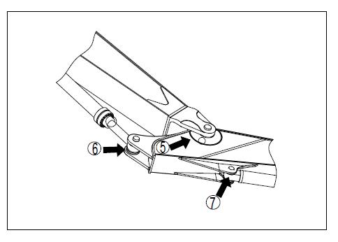
2.After excavating in the water, lubricate the pin soaking in the water. The working devices are lubricated according to the following steps: a) Adjust the working device to the posture shown below (seen in Figure 4-1), then lower the working device down on the ground and shut down the engine. b) Use the grease gun. Press the grease through the grease gun indicated by the arrow. c) Erase the squeezed old grease after adding the grease.
(1) The two hinge pins of the boom cylinder , are shown in Figure 4-2.
(2) The two hinge pins of the boom;
(3) The two ends of the piston rod of the boom cylinder;
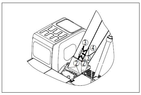
(4) The root pin of the bucket arm cylinder is shown in Figure 4-3.
(5) The two connecting pins of the boom and the bucket arm;
(6) The end of the piston rod of the arm cylinder;
(7) The root pin of the bucket cylinder is shown in Figure 4-4.
(8) The connecting pin of the arm and the connecting rod;
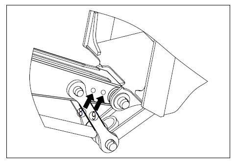
(9) The connecting pin of the arm and the bucket is shown in Figure 4-5

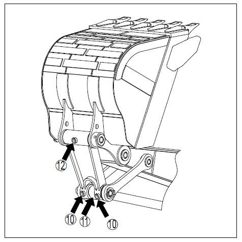
(10) The two connecting pins of the connecting rod;
(11) The end of the piston rod of the bucket cylinder;
(12) The connecting pin of the bucket and the connecting rod is shown in Figure 4-6.
4.2 Every 250 hours
4.2.1 Check the Oil Level in the Oil Pan and Refuel
Warnings a) Pull out the dipstick and wipe off the oil on the dipstick with cloths b) Insert the dipstick into the conduit completely. c) When pulling out the dipstick, the oil level is appropriate if it is between the Mark H and Mark L. d) If the oil level doesn’t reach the Mark L on the dipstick, open the oil filling port and add engine oil. e) If the oil level is higher than the Mark H, loose the oil drain plug and discharge the superfluous oil. f) After checking the oil level or refueling, insert the dipstick into the hole and install the cover of the filling port.
1. After shutting down the engine, the parts and the oil are still hot, which may cause serious scalding. Before starting operation, wait until the temperature drops.
4.2.2 Check the Oil Level in the Reducer of the Travel Motor and Refuel
Warnings
1. After shutting down the engine, the parts and the oil are still hot, which may cause serious scalding. Before starting operation, wait until the temperature drops.
2. If there is remaining pressure in the case, the oil or the screw-plug will fly out. So loose the screw-plug slowly to release the pressure. Prepare a hex wrench.

a) Lay the traveling reducer to have the Mark TOP be at the top and have the mark and the screw-plug (P) be perpendicular to the ground, seen in Figure 4-7.

b) Use the hex wrench to dismount the screw-plug (F) and check whether the oil level is within the range from the bottom of the screw-plug hole to that of 10mm (0.4 in) lower than the bottom of the screw-plug hole.
c) If the oil level is too low, install the screw-plug (F), operate the traveling lever and drive the machine forward and backward to rotate the sprocket by one round. Then repeat the second step to have a check.
d) If the oil level is still low, instill the engine oil from the hole of the screw-plug (F) until the engine oil overflows.
f) After inspection, install the screw-plug (F).
Note: There are two screw-plugs (F). When refueling, it is easy to refuel through the screw-plug hole through which people cannot see the interior gears.
4.2.3 Check the Status of the Battery Storage with the Indicator
The status of the battery can be judged by the electric eye indicator on the surface of the storage battery. Under normal good status, the electric eye indicator indicates green. But if the electric eye indicator turns white or black, as seen in Figure 4-8, the storage battery is short of electricity or lacks electrolyte. In this case, you should charge or replace the battery immediately.
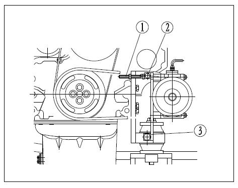
4.2.4 Check andAdjust the Tension of the Belt of theAir Conditioner Compressor
a) Check b)Adjust
Use the finger force with about 98.8N (6kgf) to press the belt in the middle part of the drive pulley and the compressor pulley, and check that the deflection is 5-8mm(0.20in-0.31in), as seen in Figure 4-9.
1) Loose the screw-plugs (2) and (3) (as seen in Figure 4-10). The bracket fixes the compressor. When loosing the screw-plugs (2) and (3), the bracket moves with the fixed position of screw-plug (3) as a pivot.
2) Loose the nut that is installed on the fixing bracket and tighten the bolt (1). Tighten it to make the deflection of the belt be 5-8mm (about 58.8N (6kgf)).
3) Check whether each belt pulley is damaged and whether the V-shape groove and the V-shape belt are worn down. Pay special attention that the V-shape belt cannot touch the bottom of the V-shape groove.
Figure 4-9 Check the belt tension of the air conditioner compressor
4) If the belt has been lengthened without margin to adjust, or if there is an incision or a crack on the belt, please replace it.
5) When adjusting the new belt, readjust it after operating for one hour.
4.2.5 Clean theAir Filter
a) Dismantle the panel at the rear of the cab, loose the installing bolt, and take down the air filter and the filter on it, as seen in Figure 4-11.
b) Use compressed air to clean the filter. If there is oil on the filter or the filter is too dirty, wash it with neutral mediums. After washing it in the water, dry the filter thoroughly before reusing it. If it is unable to remove the blockings of the filter through blowing air or washing in the water, replace with a new filter.
c)After cleaning the filter, reinstall it and install the rear panel in the cab.
The normal interval of cleaning the filters is 250 hours, but if the machine works in a workplace with much dirt, shorten the maintenance cycle and clean the filters more frequently.
Notes: if the filter is blocked, the air quantity will decrease and abnormal noisecan be heard from the air conditioner.
4.2.6 Replace the Engine Oil Filter Cartridge
Warnings
1. After shutting down the engine, the parts and the oil are still hot, which may cause serious scalding. Before starting operation, wait until the temperature drops.
The operating methods are as follows:
Filter cartridge wrench a) Dismantle the bottom cover on the bottom of the machine, and then lay a container under the drain valve (P) to receive the oil, as seen in Figure 4-12. b) To prevent the oil from splashing on your body, pull down the handle of the drain valve (P) slowly to discharge the oil, and then lift up the handle to close the drain valve. c) Open the lid on the rear right side, and then use the filter cartridge wrench to turn the filter cartridge (1) towards the left to dismantle it. d) Clean the filter seat and add clean engine oil to the new filter cartridge. Coat the filter cartridge’s sealing surface and the threads with engine oil (or coat them with a thin layer of grease), and then install the filter cartridge on the filter seat.

Warnings
1. Check that the old sealing doesn’t adhere to the filter seat. If the old sealing still retains, it will cause leaks.
e) Make the sealing surface touch with the sealing surface of the filter seat in the installation, and then tighten it for 3/4-1 round further.
f) After changing the filter cartridge, open the engine cover and add engine oil through the oil filling port (F) to a position between the Mark H and Mark L on the dipstick (G), as seen in Figure 4-13


Warnings
1. Please purchase the genuine engine oil designated by Zoomlion to guarantee the oil quality and make sure the 500-hour changing cycle.
g) Operate the engine at idle speed for a short time, and then shut down the engine and check the oil level again to make it in a position between the Mark L and Mark H on the dipstick (G). The details can be seen in “Check the Oil Level in the Oil Pan and Refuel”.
h) Install the bottom cover.
4.2.7 Replace the Fuel Filter Cartridge
Warnings
1. After operating the engine, the parts are hot. Before changing the filter cartridge, wait until all the parts cool down.
2. Keep the fuel away from open fire. Prepare a filter cartridge wrench and an oil container to receive the fuel.
a) Lay a container under the filter cartridge to receive the fuel.
b) Turn the filter cartridges (1) and (2) anticlockwise with the filter cartridge wrench to dismantle them, as seen in Figure 4-14.
c) Clean the filter seat and add clean fuel to the new filter cartridge. Coat the sealing surface with engine oil and then install the filter cartridge on the filter seat.
d) After the sealing surface touches with the sealing surface of the filter seat, tighten it for 1/2 round further.
If the filter cartridge is screwed too tight, the sealing will be damaged, resulting in fuel leak. If the filter cartridge is screwed too loose, the fuel will leak from the sealing. Therefore, the filter cartridge must be tightened to an appropriate position.
After changing the fuel filter cartridge, discharge the air in the system by using the following methods: a) Add the fuel to the fuel tank (add until the floater is at the highest position). b) After changing the filter cartridges (1) and (2), loose the exhaust screw-plug on the filter cartridge. c) Loose the button on the fuel pump and press it up and down repeatedly with hands to make the fuel flow out until there isn’t any more bubble in the fuel flowing from the exhaust screw-plug. Then tighten the button on the fuel pump. d) Tighten the exhaust screw-plug and use genuine Zoomlion filter cartridge. After changing the filter cartridge, start the engine and check whether the sealing surface of the filter cartridge leaks oil.
Notes: when the fuel is used up, discharge the air in the fuel system with the fuel pump.
4.3 Initial 500 Hours
The following maintenance is done only when new machines are initially used for 500 hours.
·Change the oil-return filter cartridge of the hydraulic oil
·Change the reducer oil of the slewing motor

·Change the reducer oil of the travel motor
Specialized tools are needed for inspection and maintenance, so please contact Zoomlion or Zoomlion dealers. The details about the methods of change or maintenance can be seen in the part “Every 250 hours, Every 500 hours, Every 1000 hours, Every 2000 hours and 4000 hours”.
4.4 Every 500 Hours
Conduct the maintenance of every 250 hours in the meantime.
4.4.1 Check
the Level of the Grease in the Slewing Pinion andAdd Grease a) Dismantle the bolts (1) (2 pieces) on the upper part of the rotating rack and dismantle the lid (2), as seen in Figure 4-15 b) Insert the dipstick into the grease and check that the level of the grease in the parts which the pinion passes by should be at least 14mm (0.6 in). If necessary, add more grease. c) Check whether the grease is milky. If so, it must be replaced. Please contact Zoomlion or Zoomlion dealers. d) Use the bolt (1) to install the lid (2).
Prepare a dipstick.

4.4.2 Check the Oil Suction Filter of Hydraulic Oil Cylinder
The oil suction filter of hydraulic oil tank should be checked every 500 hours.
4.4.3 Clean and Check the Radiator Fins, the Oil Cooler Fins and the Condenser Fins
Warnings
1. If any compressed air, high-pressure water or vapor attacks your body directly, or if you use them to blow away the dust or dirty things, there is risk of severe damage. Goggles, dust cover or other protection equipments must be used. When compressed air is used, the radiator fins may be damaged if the nozzle is too close to the radiator fins. When cleaning them, keep an appropriate distance to prevent the radiator fins from being damaged. Don’t spray air to the radiator core directly. If the radiator is damaged, water leakage and overheating may occur. In the working places with much dirt, do such inspection every day without being limited by the maintenance cycle. The procedures of cleaning and checking the radiator fins, the oil cooler fins and the condenser fins can be seen in Figure 4-16: a) Open the engine cover. b) Loose the bolts and unload the cooler. c) Clean the protection net and reinstall it. d) Before installing the protection net, check for dust, dirty things and dry leaves on every cooler fin. If any, blow them away with compressed air. Apart from compressed air, vapor or water can also be used. e) Check the rubber hose. If fissures are found in the hose or the hose has become hard because of aging, replace it with a new hose. Besides, check whether the hose has gotten loose. f) Dismantle the bottom cover and clear away the dust, dirty things and dry leaves on it.
4.4. 4 Clean the Interior of theAir Conditioner System
Warnings
1. If any compressed air, high-pressure water or vapor attacks your body directly, or if you use them to blow away the dust or dirty things, there is risk of severe damage. Goggles, dust cover or other protection equipments must be used.
2. Check the filter cartridge of air conditioner every 1000 hours, and, change the inner and outer filter cartridges together if necessary.
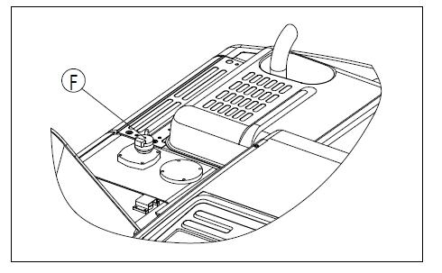
4.4. 5 Change the Filter Cartridge of the Ventilation Device in the Hydraulic Oil Cylinder
Warnings
1. 1. After shutting down the engine, the parts and the oil are still hot, this may cause serious scalding. Before cleaning the filter cartridge of the ventilation device in the hydraulic oil tank, wait until the temperature drops.
2. When dismantle the lid of the oil filling port, the oil will spray. So turn the lid slowly to release the interior pressure and then dismantle it with caution.
a) Dismantle the lid from the oil filling port (F) on the top of the hydraulic oil tank, as seen in Figure 4-17 b) Change the filter cartridge in the interior.
4.4. 6 Check andAdjust the Valve Clearance of the Engine
As special tools are required for dismantling and adjusting parts, please ask Zoomlion or Zoomlion dealers for maintenance work.
4.4.7 Lubricate the Slewing Bearings
a) Lower the working device down to the ground.
b). Pump grease by the grease gun through the nozzle indicated by the arrow in Figure 4-18.
c).After the grease is added, please wipe off the squeezed old grease
4.5 Every 1000 Hours
The maintenance work of every 250 hours and every 500 hours should be done at the same time. The oil in the swing mechanism case and the terminal transmission case needs to be changed in the initial 500 hours.
4.5.1Change the Oil-return Filter Cartridge of the Hydraulic Oil
Warnings
1. After shutting down the engine, the parts and the oil are still hot, which may cause serious scalding. Before cleaning the strainer screen of the hydraulic oil tank, wait until the temperature drops.hot
2. When dismantle the lid of the oil filling port, the oil will spray, so turn the lid slowly to release the interior pressure and then dismantle it with caution.
If the machine is installed with a hydraulic breaker, the hydraulic oil will go bad more quickly compared with machine with only bucket operation. The details for conducting maintenance work can be seen in “Maintenance for Using the Hydraulic Breaker”.
Figure 4-19 Maintenance posture of working device
The procedures of changing the filter cartridge of hydraulic oil are as follows: a) Lay the working device on firm and flat ground in accordance with the maintenance posture seen in Figure 4-19, then lower the working device down to the ground and shut down the engine. b) Dismantle the lid from the oil filling port (F) and release the interior pressure, as seen in Figure 4-20. c) Loose four bolts and dismantle the lid (1). When dismantling the lid, the lid will fly out under the the spring (2)’s force. Therefore, when dismantling the bolts, hold the lid downward. d) Take out the spring (2) and oil-return filter (3), as seen in Figure 4-21. e) Dismantle the fitting screw and the oil-return seat of by-pass valve in the oil-return filter. Take out the oil-return filter cartridge to replace it with a new one. Then install the oil-return seat of by-pass valve and the fitting screw. f) Install the oil-return filter to the previous position. g) Install the spring (2) on the top of the oil-return filter. h) Lay the lid (1) on the installing position. Then press the lid down with hands and install the lid with the mounting bolt. i) Install the lid of the oil filling port j) In order to discharge the air, start the engine in accordance with the requirements of “Start the Engine” and operate the engine at a low speed for ten minutes. k) Shut down the engine.
4.5.2 Change the Oil in the Slewing Motor’s Reducer
Warnings
1. After shutting down the engine, the parts and the oil are still hot, which may cause serious scalding. Before starting operation, wait until the temperature drops.
a) Lay a container under the drain valve at the bottom of the machine to receive the oil.
b) Open the drain valve at the bottom of the machine to discharge oil and then tighten it.
c) Dismantle the lid of the oil filling port (F) and then add engine oil with specified amount through the oil filling port (F), as seen in Figure 4-22.


d) Pull out the dipstick (G), and wipe off the oil on the dipstick with a cloth.
e) Insert the dipstick (G) thoroughly into the dipstick tube and then pull it out.
f) The oil level is appropriate if it is between the Mark H and Mark L (F). If the oil level doesn’t reach the Mark L, add oil through the oil filling port (G).
g) If the oil level is higher than Mark H, discharge the superfluous engine oil from the drain valve and recheck the oil level. When discharging the superfluous engine oil, pull out the hose from the check hole and then open the drain valve.
4.5.3 Change the Oil in the Traveling Reducer
1.After shutting down the engine, the oil is still hot. hot Before starting operation, wait until the temperature decreases.
2. If there is remaining pressure in the case, the oil or the screw-plug will fly out. So loose the screw-plug slowly to release the pressure.
Ahex wrench a) Have the reducer oil level horizontal to the ground. b) Lay an oil container under the screw-plug (P). c) Dismantle the screw-plugs (P) and (F) with the hex wrench and discharge the oil. Check whether the O-ring on the screw-plug is damaged. If necessary, replace it with a new one. d) Tighten the screw-plug (P).as shown in Figure 4-23. e)Add engine oil through the hole of the screw-plug (F). f) When the oil overflows from the screw-plug (F), install the screw-plug (F).

Tighten the screw-plugs (P) and the screw-plug (F) to the torque of38±9.8N·m
Notes: There are two screw-plugs (F). It is relatively easy to refuel through the hole of the screw-plug through which you cannot see the interior gears.
4.6 Every 2000 Hours
The maintenance work of every 250 hours, every 500 hours and every 1000 hours should be conducted at the same time.
4.6.1
Clean the Strainer Screen of the Hydraulic Oil Tank (Replace the Oil Suction Filter, in the Initial 1000 hours)
Warnings
1After shutting down the engine, the parts and the oil are still hot, which will cause serious scalding.
2 Before cleaning the strainer screen of the hydraulic oil tank, wait until the temperature drops. When dismantling the lid of the oil filling port, the oil will spray out. Therefore, turn the lid slowly to release the interior pressure and then dismantle it with caution.
a) Loose four bolts and then dismantle the lid (1), as seen in Figure 4-24. At this time, the lid may fly out under the spring (2) force. Therefore, press down the lid when dismantling the bolts.


b) Pull out the upper part of the rod (3) and remove the spring (2) and the strainer (4).
c) Clear away the dirty things adhered to the strainer screen (4) and then wash it in clean diesel or flushing oil. If the strainer screen (4) is damaged, replace it with a new one.
d) Reinstall the strainer screen (4) and insert it into the bulge (5) of the oil tank.
e) When assembling them, make the bulge under the lid (1) fasten the spring (2) firmly and then tighten it with bolt.
4.6.2 Clean and Check the Turbocharger
Please contact Zoomlion or Zoomlion dealers for cleaning and inspection work.
4.6.3 Check theAlternating Engine and the Starter Motor
If the electric brush is worn down or the bearing’s grease is used up, please contact Zoomlion or Zoomlion dealers for inspection or repairing work.
If the engine starts frequently, check it every 1000 hours.
4.6.4 Change the Oil in the Hydraulic Oil Tank
Warnings
1.After shutting down the engine, the parts and the oil are still hot which will cause serious scalding. Before cleaning the elements of the ventilation device in the hydraulic oil tank, wait until the temperature drops.
2. When dismantling the lid of the oil filling port, the oil will probably spray out. Therefore turn the lid slowly to release the interior pressure.
Make the following preparations: a) Slew the upper structure, making the drain plug under the suction tube locate in the middle part of the left track or the right track, as seen in Figure 4-25. b) Fully retract the bucket arm cylinder and the bucket cylinder, and then lower the boom to have the bucket teeth touch the ground. c) Lock the safety locking lever and shut down the engine. d) Dismantle the lid of the oil filling port (F) on the upper part of the hydraulic oil tank, as seen in Figure 4-26. e) Lay a container under the drain plug at the bottom of the machine to receive oil. Use the handle to dismantle the drain plug and discharge oil. Check the O-ring installed on the plug. If it is damaged, replace it. After discharging the oil, tighten the drain plug (1). f) Add engine oil with specified quantity through the oil filling port (F). Check the oil level and it should be between H and L on the sight gauge. The details about the methods of exhausting can be seen in the chapter “Exhaust the Air in the Hydraulic System”.
Prepare a handle used on a socket spanner.
Tightening torque: 69 ± 10 N·m. Please pay attention not to let the oil splash on your body when dismantling the emission plug.
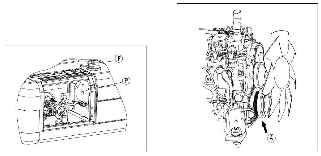
4.7 Every 4000 Hours
The maintenance work of every 250 hours, every 500 hours, every 1000 hours and every 2000 hours should be conducted at the same time.
Check the water pump
As there may be end play at the belt pulley that results in oil or water leakage or vent (A) blockage (see Figure 4-27), please contact Zoomlion or Zoomlion dealers for inspection, overhauling or replacement work.
4.8
Maintenance
If necessary
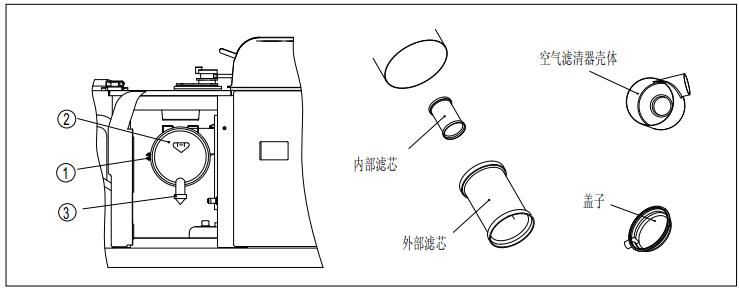
4.8.1 Check, Clean and Replace the Filter Cartridge of theAir Filter
4.8.1.1 Check and Replace the Filter Cartridge
Attention
1. If inspection, cleaning or replacement is done when the engine is running, the dust will enter into the engine and cause engine damage. Before doing these operations, be sure to shut down the engine.
2. When compressed air is used, dirty things may fly out, which may cause risk of personnel injuries. In this case, wear protection goggles, dust mask or other protective devices.
3. When dismantling the outer filter cartridge of the air filter, it is dangerous to pull out the outer filter cartridge. When working on a high point with an unstable foothold, pay attention not to fall down due to the reacting force produced from pulling out the outer filter cartridge.
4.8.1.1.1 Check
If the air filter is blocked and the alarm “air filter blocked” on the monitor gives out an alarm, it is time to clean the air filter cartridge, as seen in Figure 4-28.
4.8.1.1.2 Replacement
a) Replace the filter cartridge and the O-ring b) Replace the vacuum relay valve
If it has been over one year from installing the filter cartridge or if the air filter is blocked after cleaning the filter cartridge, it is time to replace the outer filter cartridge, the inner filter cartridge and the O-ring.
If the vacuum relay valve is damaged or the rubber deforms obviously, replace it.
Notes: Before the alarm “air filter blocked” on the monitor gives out an alarm, don’t clean the air filter cartridge. Otherwise, the air filter will not fully display its functions and the cleaning effect will become worse. In addition, in the process of cleaning operation, much dust adhered to the filter cartridge will fall into the inner filter cartridge.
4.8.1.2CleantheOuterFilterCartridge
Attention
Figure 4-28 Check the filter cartridge of the air filter a) Open the rear left door of the machine, dismantle the four clips (1) and then dismantle the lid (2), as seen in Figure 4-29. b) Hold the outer filter cartridge and shake it up and down from side to side gently. In the meantime, turn the filter cartridge from side to side and pull out it vertically. Pay attention not to dismantle the interior filter cartridge, otherwise the dust will come in to cause engine faults. Don’t use screw driver or other tools.
1. Pay attention not to let the filter cartridge be exposed to the sunshine before and after cleaning the filter cartridge.

Figure 4-29 Clean the outerfiltercartridge
c) After dismantling the outer filter cartridge, cover the air inlet in the case of the air filter with a clean cloth, so as to prevent dust or dirty things to enter it.
d) Wipe off or brush off the dirty things adhered to the interior of the lid (2) and the case of the air filter. And clean the accumulated dust or dirty things on the vacuum relay valve (2) installed on the lid (3), as seen in Figure 4-30.
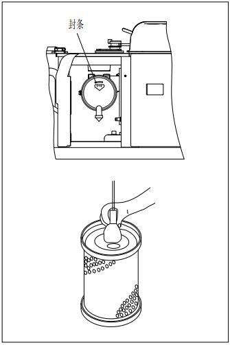
e) Blow compressed air (lower than 0.69MPa) from the inner side of the filter cartridge along the crease to the outer side. Then blow from the outer side along the crease and from the inner side to the out side again. Each time after cleaning the filter cartridge, dismantle one seal from the filter cartridge. Change the outer filter cartridge which has been cleaned repeatedly for five times or has been used for a whole year. Change the inner filter cartridge in the meantime.
If the indicator light on the instrument flickers before long the cleaned outer filter cartridge is installed, change the outer filter cartridge and the inner filter cartridge at the same time even though the filter has not been cleaned for five times.
When changing the filter cartridge, affix the seal encapsulated in the case the same as the filter cartridge. Affix the seal on the position shown in the Figure 4-31.
f) Take down the cloth or seal installed in step 3.
g) Check the filter cartridge with lamp after cleaning, change it if any small holes or thin parts on it are found. Pay attention not to strike or beat the filter cartridge when cleaning and do not use filter cartridge whose crease, sealing gasket or seal is damaged.
1. Don’t use filter cartridges whose sealing gasket, seal or crease is damaged.

2. When a filter cartridge or an O-ring has been used for over one year, it will cause problems if cleaned or used again. So replace it with a new one.
3. The sealing parts of the counterfeit component lack precision, which will make dust come in and cause engine damage. Therefore, do not use such counterfeit components.
4. Under the circumstance that the inner filter cartridge is dismantled, do not operate the engine, otherwise it will cause engine damage.
a) Check whether any dust or oil stain adheres to the sealing part of the new filter cartridge or cleaned filter cartridge.
b) When the outer filter cartridge has been dismantled, make sure that the inner filter cartridge remains at the original position. If the inner filter cartridge is oblique, use hands to insert the filter cartridge and push it upright.
c) When installing the outer filter cartridge on the case of the air filter, use hands to push it upright. It is easy to insert the filter cartridge by using hands to hold it and shaking it slightly up and down from side to side at the same time when you push the filter cartridge.
Pay attention that when inserting the filter cartridge, there will be risk of damaging the cover or the case of the filter if the rubber in the terminal part dilates or the outer filter cartridge isn’t pushed upright and you still make a hard push to install the lid (2) on the fastener (1). Therefore, pay much attention in installation.
d) Install the lid (2) according to the following steps, as seen in Figure 4-32.

1) Align the lid (2) and the filter cartridge.
2) Rotate the lid (2) clockwise until it can’t rotate, and press down the fastener (1) to the bottom.
3) If the fastener (1) can’t be pressed down to the bottom smoothly, please check whether the lid (2) rotates in place.
4) When installing the lid (2), make the vacuum relay valve face the ground.
5) When installing the lid (2), check that the gap between the case of the air filter and the lid (2) should not be too large. If the gap is too large, reinstall it.
4.8.1.4 Replace the Inner Filter Cartridge of theAir Filter
a) Dismantle the outer filter cartridge at first, and then the inner filter cartridge.
b) Use a piece of clean cloth to cover the air joint (the side of the air outlet).
c) Clean the interior of the case of the air filter and then dismantle the lid from the air inlet.
d) Install a new inner filter cartridge to the joint and then tighten the nut. Pay attention not to clean and reuse the inner filter cartridge. When changing the outer filter cartridge, change the inner filter cartridge in the meantime.
e) Install the outer filter cartridge in the right position and then lock the lid (3) with the clip (2).
4.8.2 Clean the Interior of the Cooling System
Warnings
1. After shutting down the engine, the coolant is still hot and the radiator has a relatively high interior pressure. If dismantling the lid to discharge the coolant now, there is risk of scalding. Before dismantlement, wait until the temperature drops and turn the lid slowly so as to release the pressure.
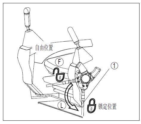
2. Do cleaning when the engine is running. When standing up or leaving from the operator’s seat, adjust the safety locking lever to the LOCK position.
3. The details about starting the engine can be seen in section of Chapter four “Start the Engine” in the Operation Manual.
4. If the protecting cover in the bottom is dismantled, there is risk of touching the fan. When the engine is running, don’t enter the rear part of the machine. Clean the interior of cooling system and replace coolant and corrosion inhibitor according to Table 4-1.
Table4-1Changethecoolingliquidandcorrosioninhibitor
Typesofcoolingliquid
Permanent antifreeze (applicable in all seasons)
Impermanent antifreeze which contains glycol (applicable only in winter)
When antifreeze is not used
Clean the interior of cooling system and change coolant
Change every year (in autumn) or every 2000 hours, whichever arrives first
Change every six months (in spring and in autumn). (Discharge antifreeze in spring and add antifreeze in autumn)
Change every six months or every 1000 hours, whichever arrives first
Changetheanti-corrosion device(optional)
Every 1000 hours or when cleaning the interior of the cooling system and changing the cooling liquid
As the mixture ratio of the additive in different antifreezes is different, please do not mix them up. Please clean and change after shutting down the machine in a flat place. The mixture ratio varies with the ambient temperature. The minimum ratio should be 30% in accordance with the volume.
When determining the proportion of the antifreeze and the water, check the previous lowest temperature and determine it according to the mixture ratio table given. Meanwhile, you’d better underestimate the temperature by 10°C.
1. The antifreeze is inflammable, hence put it far away from flame.
2. The antifreeze is poisonous, so pay attention not to let the coolant with the antifreeze splash into eyes when dismantling the drain plug. In case of an emergency, use a large amount of water to wash the eyes and seek medical treatment immediately.
The tap water should be used as the coolant. If the river water, well water or other such water sources must be used, please contact Zoomlion or Zoomlion dealers. In order to control the mixture ratio, the densitometer is recommended for use. Prepare a container to receive the discharged coolant and prepare a hose to add water. The operation methods as follows: a) Turn the radiator lid (1) slowly and dismantle it, as seen in Figure 4-33. b) Dismantle the bottom cap, and then lay a container under the drain valve to receive the coolant Open the drain valve on the bottom of the radiator to discharge the cooling liquid. c) After discharging the coolant, close the drain valve and add tap water. When the radiator is added full with water, start the engine and run it at a low speed to have the temperature rise to at least 90℃, and then continue operating it for about ten minutes. d) Shut down the engine and open the drain valve to drain the water. e) After draining the water, clean the radiator with the detergent. As to relevant cleaning method, please comply with the instructions of the detergent. f) Close the drain valve. g) Install the bottom cap. h) Add water to the water injecting hole through the water injector. i) Operate the engine for about five minutes at a low speed and then operate it for five minutes at a high speed so as to discharge the air mixing in the coolant (at this time, the radiator lid (1) has been dismantled). j) After discharging the coolant in the auxiliary water tank (3) (as seen in Figure 4-34), clean the interior of the auxiliary water tank and then add water until the liquid level is between Full level and Low level. k) Shut down the engine. About three minutes later, add water through the water injecting hole and then tighten the radiator lid.
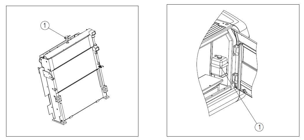
4.8.3 Check and Tighten the Bolt on the Track Shoe
If the machine is used in the situation that the bolt (1) on the track shoe is loose (as seen in Figure 4-35), the bolt will be broken. Therefore, tighten the loose bolt right away.
4.8.3.1 Tightening Methods
a) Track shoe b) Road pad
Tighten with a tightening torque of 490±49N·m (50±5kgf·m), and then check whether the nut and the track shoe get in touch closely with the contacting surface of the chain. After checking, further tighten it by 120°±10°.
Tighten with a tightening torque of 549±59N·m (56±6kgf·m), and then check whether the nut and the track shoe get in touch closely with the contacting surface of the chain link.
4.8.3.2 Tightening Sequence
Tighten the bolt according to the sequence shown in Figure 4-36. After tightening, check whether the nut and the track shoe get in touch closely with the mating surface of the chain link.
4.8.4 Check andAdjust the Tension of the Track
The wearing condition of the pins and pin bushes on the lower part of the machine varies with the operation conditions and the soil type. Therefore, check the tension of the track regularly to keep standard tension. Stop the machine on flat and firm ground when checking and maintaining it.
4.8.4.1 Check
a) Run the engine at a low idle speed. Move the machine forward for a distance that equals the ground contact length of track and then halt the machine.
b). As seen in the right figure, choose a long rod and put it on the track above the idler (1) and the carrier roller (2), as seen in Figure 4-37.
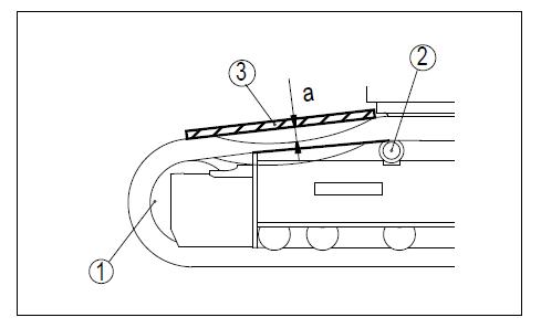

c). Measure the maximum distance between the upper surface of the track and the bottom of the long rod. The standard distance: the sag “a” should be 10 ~30 mm (0.4 ~1.2 in). If the tension of the track is not within the standard value, adjust it according to the following methods.
4.8.4.2
Adjust
Attention
1. The screw-plug (1) may fly out under the high pressure of the grease. So make sure not to loose the screw-plug (1) for more than one round.
2. Don’t loose any parts except the screw-plug (1) and don’t face towards the installing direction of the screw-plug (1).
3. If the methods provided here can not make the tension of the track loose, please contact Zoomlion or Zoomlion dealers.
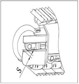
4.8.4.2.1 When augmenting the tension
Prepare a grease gun and operate as the following steps: a) Use the grease gun to add grease through the nozzle (2) (seen in Figure 4-38) (the nozzle (2) and the screw-plug (1) become one). b) To check whether the tension of the track is appropriate, move the machine forward slowly (7-8 m). c) Check the tension of the track again. If the tension is not appropriate, adjust it again. d) Continue to add grease until the size S is zero (0), as seen in Figure 4-39. If the tension is still loose, maybe it is due to the excessive wearing of the pin and the pin bush. Therefore, turn it upside down or replace it; please contact Zoomlion or Zoomlion dealers for the repair work.

4.8.4.2.2 When loosening the tension
Warnings
1. Apart from the procedures provided below, it is very dangerous todrain the grease using any other procedures.
2. If the tension of the track can not be loosened according to this procedure, please contact with Zoomlion or Zoomlion dealers for the repair work.
a) Loose the screw-plug(1) (as seen in Figure 4-39) gradually to discharge the grease.
b)Turnthe screw-plug(1) for at most one round.
c) If the grease can not come out smoothly, move the machine forward or backward for a short distance.
d) Tighten the screw-plug (1).
e) To check whether the tension of the track is appropriate, move the machine forward slowly by 7-8m.
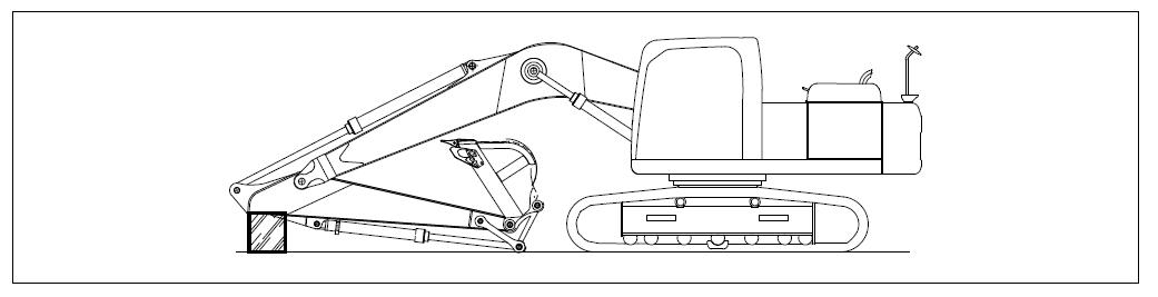
4.8.5 Replace the Bucket Teeth
Before the bucket teeth seat is worn down, change the bucket teeth according to the following methods:
Warnings
1. When changing the bucket teeth, it is very dangerous if the working device moves due to incorrect operation. Please place the working device in a stable state and then shut down the engine and lock all the operating levers firmly.
2. If using too strong force to strike the lock pin, the lock pin may fly out. So check to make sure that there are no people in the surrounding areas.
3. When conducting replacement, there will be flying objects. Therefore, please wear safety goggles, gloves and other protection equipments.
a) Lay the bottom of the bucket on the cushion block so that the pin (1) can be dismantled, as seen in Figure 4-40. Check that the working device is in the stable state and then place the safety locking lever to the locked position. Lay the bottom of the bucket horizontally.
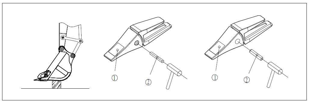
b) Put a metal rod on the pin head and use a hammer to strike the metal rod, so as to tap out the pin (1). Then dismantle the bucket tooth (2).
Remark: need to use a metal rod whose diameter is a little smaller than the pin.
c) Clean the installing surface and install the new bucket tooth (2) on the tooth seat. Use hands to push the pin (1) partially and then use a hammer to strike and lock the pin so that the bucket tooth is installed on the tooth seat.
4.8.6Adjust the Gap of the bucket
1. When adjusting the gap, it is very dangerous if the working device moves due to incorrect operation.
2. Please place the working device in a stable state and then halt the engine and lock the safety locking lever firmly.
a) Place the working device in a state that is shown in Figure 4-41. Halt the engine and lay the safety locking lever in the locked position, as seen in Figure 4-42. Remove the O-ring (1) of the connecting rod and measure the clearance “a”.

b) If moving the bucket to one side or measuring the total clearance at one place, the measuring work will be much easier. (The left-hand position is seen in the picture) It will be easy to use plug (clearance) gauge to measure precisely.
c) Loosen the four fixed screw-plugs (2) and then loosen the plate (3). Because snap ring spacer is adopted, the operation can be done with the bolts not dismantled.
d) Dismantle the spacer (4) according to the clearance quantity “a” measured above.
[For example]: when the clearance is 3mm, dismantle two spacers of 1.0mm and a spacer of 0.5mm, and the clearance turns to be 0.5mm. For the spacer (4), two types (1.0mm and 0.5mm) are adopted. When the clearance is smaller than a spacer, do not do any maintenance.
e) Tighten the four bolts (2). If the bolt (2) can not be tightened easily, pull out the stop pin bolt (5) to facilitate tightening.
Liquid
The liquid storage tank (1) is in the left rear door of the machine. If there is air in the cleaning fluid of the window washer, check the liquid level of the liquid storage tank (1). If necessary, add the cleaning fluid of the window washer, as seen in Figure 4-43. When adding the liquid, pay attention not to let the dusts enter.

As the mixture ratio varies with the ambient temperature, please add the cleaning fluid based on the mixture ratio in Table 4-2 which has taken the ambient temperature into consideration.
The pure cleaning fluid is divided into two types: one type is applicable to -10℃ (14℉) (for general use) and the other type is applicable to -30℃ (-22℉) (used in cold regions). Use the pure cleaning fluid according to the operating regions and seasons.
Cleaning Fluid
4.8.8 Check andAdjust theAir Conditioner
4.8.8.1Check the Liquid Level of the Refrigerant (gas)
1. If the refrigerant enter into your eyes or moisten your hands, there is risk of blindness or frostbite. So don’t get in touch with the refrigerant. Do not loosen any parts in the pipeline of the refrigerant.
2. Don’t let any open flame get close to location of refrigerant leaks. In case of refrigerant shortage (R134-a), the cooling performance will be very poor. When the engine is running at high idle speed, the air conditioner is in the state of strong refrigeration. There should be no bubbles in the observation window (inspection window) installed on the liquid storage tank of the condenser, as seen in Figure 4-44.
No bubbles flow in the refrigerant: ok
There are bubbles flowing in the refrigerant (the bubbles go through successively): the liquid level of the refrigerant is low
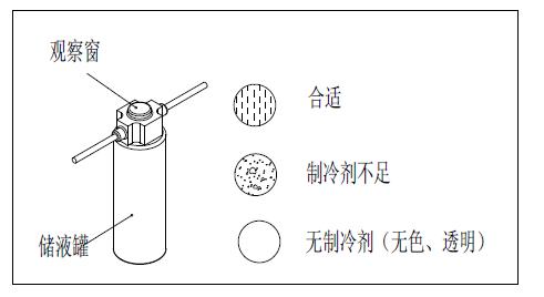
Colorless and transparent: there is no refrigerant
Note: when there are bubbles, the liquid level of the refrigerant will be low. At this time, please contact Zoomlion or Zoomlion dealers to add the refrigerant. If the air conditioner works when the liquid level of the refrigerant is low, the compressor will be damaged.
4.8.8.2 Check in the Spare Seasons
When the machine is not used for a long time, please operate the cooler for three to five minutes once a month to provide lubrication for all the parts of the compressor. The inspection and maintenance items for the cooler can be seen in Table 4-3.
condition, (check if the connecting part is loose or if there is gas leak or damage)
4.8.9 Stop Methods for Machines on the Slope
Generally speaking, the machines should not be parked on slopes; when it must be parked on slopes in special situations, do according to the following methods:
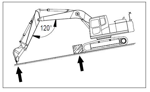
4.8.9.1 Method of using Slope
1. Choose a stiff and flat place.
2. Put a cushion block under the track to prevent the machine from moving and insert the working device into the ground.
a) Stop the machine and make the working device be on one side of the downhill, as seen in Figure 4-45.
b) Put a cushion block under the track and insert the working device into the ground.
4.8.9.2 Methods of Using the Cushion Block
1. Choose a stiff and flat place.
2. Lay a solid cushion block under the under part of the machine to stabilize the machine. Pay special attention when operating it.
a) Use the boom and the bucket arm to put up the lower part of the machine, as seen in Figure 4-46. At this moment, operate the control lever slowly.
b) Insert the cushion block firmly between the ground and the tracks which are put up to make sure that the machine is stable.
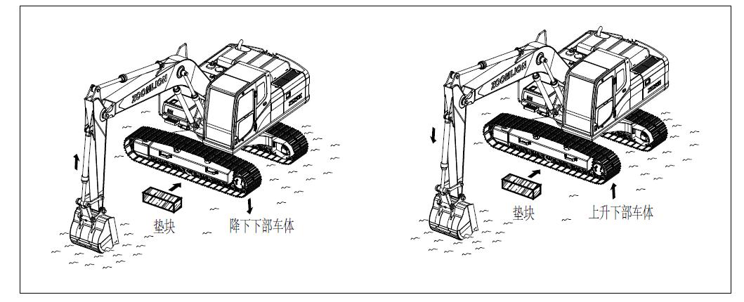
c) Lift the boom slowly and lower the machine. At this moment, check to make sure that the machine is stable all the time.
4.8.10 Discharge theAir in the Hydraulic System
The relevant details can be seen in section of Chapter four “Start the Engines” in the Operation Manual
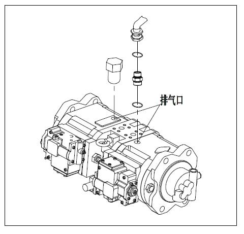
4.8.10.1 Discharge theAir in the Pump a) Loosen the exhausting screw-plug and check whether there is oil leakage. b) If there is no oil leakage, dismantle the discharging hose from the hydraulic pump and add the hydraulic oil through the vent to the hydraulic pump, as seen in Figure 4-47. Fix the dismantled hose firmly and make the mouth of pipe higher than the oil level in the hydraulic oil tank so that the oil cannot eject form the hose. c) After finishing exhausting, tighten the exhausting screw-plug at first and then install the discharging hose.
Notes:
If you install the discharging hose at first, the oil will spray from the exhausting screw-plug.
·If you operate the pump when the pump is not fully filled with oil, the pump will overheat and cause premature damage to pump.
4.8.10.2 Start the Engines
The relevant details can be seen in the section of Chapter four “Operation for the Engines” in the Operation Manual.After starting the engine, operate it for ten minutes at a low speed and then start operation.
4.8.10.3 Discharge theAir in the Cylinder
a) Operate the engine at low speed. Extend or retract the cylinders to a position that is 100mm (3.9in) from the end of stroke for four or five times (pay not to fully extend or retract the cylinders).
b) Then fully operate every cylinder for three or four times.
c)At last, fully operate every cylinder for four or five times to discharge the air completely.
Notes:
·If immediately run the engine at high speed or fully operate the cylinder, the air in the cylinder will damage the piston seal.
4.8.11 Methods of Releasing the Interior Pressure in the Hydraulic Pipeline
Warnings
1. The hydraulic oil pipeline is under high pressure all the time, so you should release the pressure in the pipeline before checking or changing the pipes or hoses. If the pressure is not released, the high pressure oil will spray and cause serious personal injuries.
2. After shutting down the engine, the parts and the oil are still hot, which will cause severe scalding. Before starting operation, wait until the temperature drops.
3. When dismantling the lid of the oil filling port, the oil will spray out. Therefore, before dismantling the lid, turn it slowly to release the interior pressure.
a) Stop the machine on horizontal and stiff ground, as seen in Figure 4-48.
b) Within the fifteen seconds after halting the engine, turn the starter switch to ON position and fully operate the control levers (for the working device or traveling) towards different directions to release the interior pressure.
c) Loosen the refueling lid (F) on the top surface of the hydraulic oil tank (as seen in Figure 4-49) to release the interior pressure.

4.9 Maintenance of Hydraulic breaker
If the machine is installed with hydraulic breaker, the maintenance schedules of some parts will be different.
For the machine installed with hydraulic breaker, the hydraulic oil deteriorates more quickly than that with only bucket excavating operation. Hence, adjust the maintenance schedule in accordance with the following steps.
4.9.1 Change the Hydraulic Filter Cartridge
As for the new machines, change the filter cartridge after the first 100 to 150 hours and conduct further replacement according to Figure 4-50.
4.9.2 Change the Oil in the Hydraulic Oil Tank
Change the oil in accordance with the Figure 4-50.
4.9.3 Change theAdditional Filter Cartridge Used for the breaker
Use the breaker’s 250 hours of usage as guide (the operating frequency of the breaker: more than 50%) and change the filter cartridge in accordance with the Figure 4-50.
C hanging cycle
(When do not use the breaker)
Replacement cycle of the hydraulic oil

Filter cartridge of the hydraulic oil
(When use the breaker only) Additional filter cartridge
The operating frequency of the breaker (%)
ZE205E/ZE230E HYDRAULIC EXCAVATOR MAINTENANCE MANUAL
Chapter Five: Troubleshooting of Common Faults
Chapter Five: Troubleshooting of Common Faults
5.1 Description of Normal Phenomena instead of Faults
Please notice that the following phenomena are not faults:
1. When the arm is retracted, the moving speed declines instantaneously when the bucket arm exceeds or is below the vertical line.
2. When the bucket teeth exceed or are below the horizontal line, the speed of arm declines instantaneously.
3. When doing heavy-load excavation, the bucket or bucket arm vibrates.
4. When starting or stopping slewing, there is noise of brake valve.
5. When marching down an abrupt slope at a low speed, the travel motor makes noise.
6. When operating the bucket or bucket arm, the control valve makes noise.
7. When operating the bucket arm or bucket with the engine idling, the bucket arm or bucket works slowly.
8. When the engine starts or the engine is almost idling, the vibration of the machine becomes intense. But if the engine speed is increased slowly, this co-vibration will disappear.
1. In the following tables 5-1, 5-2 and 5-3, please contact Zoomlion or Zoomlion dealers when dealing with items in the brackets.
2. If any faults or reasons not listed in the following tables appear, please contact Zoomlion or Zoomlion dealers for repair.
5.2. Electrical System
The common faults and the troubleshooting methods of the electrical system can be seen in table 5-1.
Table 5-1
Troubleshooting of common faults of electrical system
1 Even if the engine is running at high speed, the illuminating light is still off
Wire fault or battery deterioration
2 When the engine is running, the illuminating light flashes The fan belt is loose
3 Even if the engine is running, the charging indicator doesn’t go off
4 The alternator makes abnormal noise
5 When starting the machine, the starter motor doesn’t work
6 The pinion of the starter motor sometimes works but sometimes doesn’t work
(Check and repair the loose terminals and open circuits or change batteries)
Check the tension of the fan belt and change it
Alternator fault (Change)
Wire fault
(Check and repair)
Alternator fault (Change)
Wire fault
(Check and repair)
Fault of starter motor (Change)
The battery storage is undercharged Charge
The battery storage is undercharged Charge
Fault of safety relay (Change)
7 The starter motor drives the engine slowly
8 Before the engine starts, the starter motor disconnects
9 When the engine is shut down, the engine oil pressure indicator doesn’t work (the starter switch is at the ON position)
5.3 Hydraulic System
The battery storage is undercharged Charge
Fault of starter motor (Change)
Wires fault, the circular pinion’s fault (Check and repair)
The battery storage is undercharged Charge
Indicator fault (Change)
Fault of the warning light switch (Change)
The common faults and the troubleshooting methods of the hydraulic system can be seen in Table 5-2.
Table 5-2 Troubleshooting of common faults of hydraulic system
1 The hydraulic pressure functions slowly
The oil level is low Refill the oil collector to the full scale
The oil is cold
The engine speed is too low
Preheat the machine your designated dealer The pump is worn down your designated dealer The suction pipeline of the pump is blocked
Gas leak of the pump’s suction pipe
The hydraulic pump is worn down
Contact
Install and straighten the blade your designated dealer
Adjust the
Contact your designated dealer
Add
Clean
5.4 Engine Parts
The common faults and the troubleshooting methods of the engine can be seen in Table 5-3.
Troubleshooting
1 The engine oil pressure indicator light is on
The engine oil filter is blocked Change the filter
The oil pipe and the joint are loose, or the damaged part leaks oil (Check and repair)
Fault of engine oil pressure sensor (Change the sensor)
Indicator fault (Change)
The liquid level of the cooling liquid is low, water leak
Check, add water, and repair
2 The vapor squirt from the top of the radiator (the pressure valve)
The fan belt is loose
Dirty things or lime scale is accumulated in the cooling system
Check the tension of the fan belt; adjust and change
Change the cooling liquid, and wash the interior of the cooling system
No. Fault description
3
The radiator coolant level indicator light is on or the coolant temperature pointer points to the red zone
Table 5-3 (Continued)
Main causes
Solutions
The cooling fin is blocked or damaged Clean or repair it Thermostat fault (Change the thermostat)
The lid of the coolant injection port on the radiator is loose (high altitude operation) Fasten the radiator lid or change the seal
Fault of coolant level and temperature sensors (Change the sensor)
Indicator fault (Change)
The fuel is not enough Refuel
There is air in the fuel system Repair the part that sucks air
4 The engine doesn’t start when the starter motor rotates
Fault of injection pump or injection nozzle (Change the injection pump or the injection nozzle)
The starter motor starts the engine slowly Contact your designated dealer
Compression fault (the valve clearance is not correct) Contact the designated dealer (adjust the valve clearance)
5 The exhausting gas becomes white or blue
The oil inside the oil pan is too much Adjust the oil to the specified oil level
The fuel is not suitable Change to the specified fuel
The filter cartridge of the air cleaner is blocked Clean or change
Fault of injection nozzle (Change the injection nozzle)
6 The exhausting gas sometimes becomes black
Compression fault (Refer to the above compression fault )
Turbocharger fault
Clean or change the turbocharger
7 Air bleeding sound can be heard occasionally in the burning noise
Fault of injection nozzle (Change the injection nozzle)
The fuel grade used is low Change to the specified fuel
8 Abnormal noise is heard (burning or mechanical)
It is too hot
Refer to the above fault “The radiator coolant level indicator light is on”.
The interior of the muffler is damaged Change the muffler
The valve clearance is too large (Adjust the valve clearance)