
25 minute read
Chapter Five Operation


5.1 Inspection before operation
5.1.1 Precautions to be taken before operate the machine.
The life time of crane is influenced deeply by the initial use of it. So careful precautions should be followed as below:
1. The initial 50-100 hours is match-up period, and during this period try to take all the possible measures to prevent machine from big load shocks.
2. Daily inspection should include engine, hydraulic system, working attachments and other running parts besides general inspection.
5.1.2 Inspect the machine before operation
1. Check list for daily maintenance
Item
Visual inspection
Descriptions
Any damages and parts missing or loosing caused during transportation
Hydraulic system Check if there is any oil line leakage or surface scratches of the hoses.
Cooling system Fill up cooling water whenever is needed and check if there is any leakage.
Fuel system Fill the fuel tank with diesel fuel that has been deposited for over 24 hours.
Electrical system Check that any loosing or abnormal wire connections.
2. Inspection before operation
Execute daily inspection for all the points shown below before use of the crane: See Fig. 5-1.
Switches,buttonsand controlleverscheck
Boltscheck
Wireropecheck
Safetydevicecheck
Hydraulicsystem leakagecheck
Hydraulicoil check
Engineoilcheck
Radiatorcheck
Fueltankcheck
5.2 Layout of control system
5.2.1 Layout of control system
See
5.2.2 Names of above index
The indicator lights up (green) – charge; the indicator goes out – no charge.
4. Waiting for start indicator
When the environmental temperature is below minimum start–up temperature of engine, the preheat system automatically starts to heat up, and the green indicator lights up. After the green indicator goes out it means the machine has finished preheat and the engine is ready for start up.
5. Power indicator
This indicator lights up when the starting switch turns on.
6. Troubleshooting indicator (Yellow)
The yellow indicator lights up to show there is trouble in the engine and the engine should be stopped to check and repair.
7. Engine stop indicator (Red)
When any error occurs in the engine, this red indicator will light up and shows an error code simultaneously.
8. 78º limit buzzer indicator
The indicator lights up and the buzzer sounds to show that boom exceed 78º.
9. Hook limit indicator
The indicator lights up and the buzzer sound to show hook over-hoist.
10. Display of anemometer
11. Oil return filter element alarm indicator
The oil tank is equipped with signal generator. When the filter element is plugged, the indicator will light up and become red.
12. Monitor switch
13. VCD player
14. Spotlight
15. Rear view light
16. Joystick of pilot valve (Swing,Aux. winch)
17. Power switch
18. Swing control switch
19. Main winch pawl switch
20. Aux. winch pawl switch
21. Derricking pawl switch
22. Pressure changeover switch
23. Swing lock switch
24. Fuse
25. A-frame rise/lower switch
26. Aux. hook clutch
27. Lock, aux. hook clutch
28. Main hook clutch
29. Lock, main hook clutch
30. Control system release switch
31. Swing control switch
32. Control joystick for aux. winch flow addition
33. Pedal for aux. winch brake
34. pedal for main winch brake
35. Pedal accelerator
36. Pressure control switch
37. Switch for swing indicator
38. Horn
39. Main winch lower switch
40. Pilot valve for travel left
41. Engine start switch
42. Hand throttle
43. Adjusting switch
44. Troubleshooting switch
Used for finding engine error
45. ISC 3 1400rpm
46. ISC 2 1600rpm
47. ISC 1 1800rpm
48. Emergency stop switch
49. Pilot valve for travel right
50. Joystick for pilot valve (Derricking, main winch)
5.3 Operation of servo system
Layout of control levers and switches for servo system is shown in Fig.5-3.
Operation:
Place power switch 17 in ON position. Then start the engine. (For more details about operation of the engine, see following descriptions.)
Push lever 36 forward, this lever is main switch of servo system. Then servo system is supplied with oil. The servo pressure is 4Mpa.
5.4 Operation of A-frame
Layout of switches for operation of A-frame is shown in Fig.5-4.
Operation:
Before A-frame rising and lowering, place pressure changeover switch 22 in Superstructure position. Operate A-frame rise/lower switch 25. A-frame raises when switch 25 is in UP position; A-frame lowers when switch 25 is in DOWN position. A-frame stops when switch 25 is in OFF position.
Note:After operation, switches 22, 25 are in the neutral position. Insert the fixing pin.
5.5 Operation of the engine
Layout of switches and control levers for the engine is shown in Fig. 5-5.
5.5.1 Start the engine
1. Before starting the engine, switches, joysticks of pilot valve should be in neutral position. Accelerator pedal should be in up position and hand throttle should in neutral position.
2. See Fig. 5-6, insert key into switch 41 and turn the key to Position I, then the starter is powered on and all indicators of electrical system flash and go out one by one. Turn the key to Position II to start up the engine. NEVER keep the key at Position II for more than 15 seconds to avoid damage of the starter. If start-up fails, release the key and wait for no less than 30 seconds and start it again. Do not remove the hand from the key because the start switch is a type of auto-reset.
3. After engine start release the key and it will automatically return to Position I.
4. After start up, switch the engine to idle speed to warm up, this is good for long life use of engine.
A. The preferable cooling water temperature of engine is 80-95, if running below 60, it ℃℃ will cause extra consumption of fuel and abnormal wear of engine.
B. The preferable working temperature of hydraulic oil is 30-80. If working under 20,℃℃ any jerk actions may cause damages of motors, valves or pipe lines. Before operation, please warm up the engine to let cooling water and hydraulic oil reach suitable temperature.
First keeps the engine idling for 5 minutes. Above steps are not necessary if the temperature is over 20℃. In winter and cold area, above steps should be performed twice or more to make the temperature of cooling water over 60℃ and working oil over 20℃, and keep engine speed at 1000rpm, servo pressure at 5Mpa.
5.5.2 Stop the engine
1. Before stop the engine, keep the engine at idling status for 5 minutes, and then turn the starter switch 41 from Position II to OFF position to cut off the power and the engine stops. Never leave key in machine.
2. When starter switch is at Ⅱ position, to stop the engine by pressing emergency stop switch 48 in case of emergency, but it is not under idling position when the engine stops. Once the emergency stop button is pushed down, it will be locked. To unlock the button by turning it clockwise for next time use. (Under engine idling status, you can also press the emergency stop button to stop the engine.)
5.5.3 Engine speed adjustment
The engine speed can be controlled via hand throttle, pedal accelerator and speed switches, and details as follows:
1. Hand throttle control: by turning the hand throttle switch 42 to realize engine variable speed control.
2. Pedal accelerator control: by stepping on accelerator pedal 35 to realize engine variable speed control.
3. Fixed speed selection button:
Speed 1: 1800rpm (switch 47 engages solely)
Speed 2: 1600rpm (switch 46 engages solely)
Speed 3: 1400rpm (switch 45 engages solely)
Three fixed speed can be got by operating switches 45, 46, 47 separately. The fixed speed function has priority over the hand throttle and pedal throttle control. For further information about engine operation please refer to Operation Manual of Engine
5.6 Hoisting operation
Layout of switches for hoisting operation is shown in Fig. 5-7.
5.6.1 Main hoisting operation
Joystick 50 is for derricking and main hoisting operation. By pressing down or releasing main winch flow addition switch 51; there are two ranges of stepless speeds available:
1. Low speed (0-35m/min) hook lowering operation: hold down Button 39 and push the joystick 50 forward.
2. Low speed (0-35m/min) hook hoisting up operation: pull joy stick 50 backward.
3. High speed (35-70m/min) hook lowering operation: press and hold Button 39 and Button 51 and push forward joy stick 50.
4. High speed (35-70m/min) hook hoisting up operation: press and hold Buttons 51, 39 and pull backward the joystick 50.
Note: It is strictly forbidden to do high speed slewing action during hook hoisting up or lowering down.
5.6.2 Aux. hoisting operation
Joystick 16 is for slewing and aux. hoist operation. By pressing down flow addition switch 32, there are two ranges of stepless speeds available:
1. Low speed (0-35m/min) aux. hook lowering operation: push the joystick 16 forward.
2. Low speed (0-35m/min) aux. hook hoisting up operation: pull joystick 16 backward.
3. High speed (35-70m/min) aux. hook lowering operation: press and hold flow addition switch 32 push forward joystick 16.
4. High speed (35-70m/min) aux. hook hoisting up operation: press and hold flow addition switch 32and pull backward the joystick 16.
Note: It is strictly forbidden to do high speed slewing action during auxiliary hook hoisting up or lowering down
5.7 Derricking operation
Push pilot valve joystick 50 right, boom raises. Push pilot valve joy stick 50 left, boom lowers.
Pilot valve joy stick 50 is at neutral position, boom brake is engaged.
Note: Before boom lowering operation, first lift up the boom a little then lower down the boom, this can prevent the derricking winch pawl from being deadlocked.
5.8 Brakes and locks for main hoist, aux. hoist and derricking
For safety consideration, this machine is equipped with normally closed band-type brake for its main and aux. hoist winches. When control joysticks of winches are in neutral position, the control oil line is cut off and brake cylinder is disengaged, and the band type brake is engaged by the spring force. So does the derricking winch brake.
See Fig. 5-9 below:
On the drums of main/aux. and derricking winches there are pawls to lock them up during transportation and repair.
Before the operation of main, aux. winch or derricking winch, keep the switch 19, 20, or 21 to ON position to disengage pawl from the drum, then the winch can work for hoisting. When the system stops, keep the switch 19, 20 and 21 to OFF position to lock the drums with pawls.
5.9 Swing operation
Note: Release swing brake first before swinging.
Swing brake is normal open brake. Press swing control switch 31 which on left joy stick to engage the brake; Swing brake engages continuously when swing control switch 18 which on the right control panel is at ON position. Set swing control switch 18 in OFF position to release the brake.
Push pilot valve (joy stick) 16 left, press light/buzzer switch 37 at the same time, swing the superstructure left and buzzer buzzes.
Push pilot valve (joy stick) 16 right, press light/buzzer switch 37 at the same time, swing the superstructure right and buzzer buzzes.
The swing speed can be proportionally controlled by the offset degree of joy stick.
Cautions for swing operation:
○ 1 Only low speed swing operation is allowed when perform main and aux. hoist or lower operation.
○ 2 Swing should be smooth and keep the load moving steadily without jerking actions.
○ 3 To stop swinging by operating the joy stick reverse, the operation should be done slowly.
○ 4 Hydraulic swing brake is only for temporary stop of swing operation.
○ 5 Swing lock must be applied during transportation or stop the swing operation continuously.
After finishing work or during transportation, and in case of the crane parks on a slope, swing lock pins should be engaged to fix the superstructure. There are 4 locking positions applicable and controlled by swing lock switch 23 switch on the left control panel.
5.10 Travel operation
When traveling operation is performed, switch the transfer valve lever which on the right catwalk to traveling position. See Fig. 5 15.
Travel Cylinder
No. 40, 49 are for left and right traveling.
Step the pedal forwards for going forward. Step the pedal backwards for back traveling. Operate left or right traveling pedal (lever) separately for turning, but jerk operation should be avoided.
Note:
○ 1 For long distance traveling, set the traveling motor at rear and travel forwards as per the direction of the arrows which are on the side frames.
○ 2 The best rotation speed of the engine is 1700rpm for long distance traveling.
Traveling brake:
Traveling brake is normal close brake. When the control lever is at neutral position, the pressure oil circuit is cut; the brake is engaged by the spring force. When the engine stops, even the pedal (lever) is at other position, the brake keeps at the brake status. When the machine parks on a slope, put wedges under the tracks once the operator leaves the cabin.
Note: When the machine parks on a slope, put wedges under the tracks once the operator leaves the cabin.
5.11 Undercarriage cylinder operation
Before operation of undercarriage cylinders the conversion switch bar on the right platform should be shifted to “Cylinder” position. See Fig. 5-18 below:
Pilot valve (pedal) 40 is for extension and retraction cylinder
Step the pedal forwards – cylinder and tracks extension; Step the pedal backwards – cylinder and tracks retraction
Undercarriage extension and retraction:
1. Under transportation condition, pull out the left fixed pins (at the side of bigger size cylinder).
2. Rotate extended bracket on left side as shown in Fig. 5-21.
Extendedbracket
3.Turn extended bracket till it is vertical to the carbody, insert the jacket as shown in Fig.
4.Step the pilot valve(pedal) 40 forward slowly to make the cylinder extend. After cylinder extending, fix the limit pins and dowels. Adjust the stoppers and fix them.
5. Repeat above steps to extend another track. Adjust the adjusting screw to make it contact against the side frame tightly.
Adjustingscrew
6.Reverse above steps to retract the tracks.
Adjustingscrew
5.12 Free fall
This crane is equipped with free fall system which can greatly increase productivity.
5.12.1 Structural sketch of normally closed band type brake and clutch.
Adjustingbolt
Brakeband
Adjustingbolt
Adjustingbolt
Clutchlever
Clutchspring
Adjustingbolt
Cylinder
Clutchband
Adjustingbolt
Adjustingbolt
Adjustingbolt
Brakelever
Brakecylinder
Pointbrakecylinder
Brakespring
5.12.2 Working principles
Clutchcylinder
Pointbrake cylinder
Brake cylinder
Pointbrake cylinder Main winch
Aux. winch
Brake cylinder
Hydrauliccontrol valve1
Hydrauliccontrol valve2
Pilotvalve
Solenoid valve1
Solenoid valve2
Solenoid valve1
Solenoid valve2
Footvalve
Hydrauliccontrol valve1
Hydrauliccontrol valve2
Pilotvalve
This crane has two working modes: normal working mode and free falling mode.
The normal working mode is a kind of active mode, when there is no action the winch brake is in engaged status. When running the winch, the control valve control oil pressure to engage the brake cylinder and the brake is disengaged, and the winch is rotated by the friction force between the inner surface of the winch and the clutch (the clutch is driven by the reduction gear linked with the hydraulic motor. In short, in normal working mode the winch control bar control the winch brake (disengage it) and winch clutch (engage it) to work simultaneously. So under this mode the operator doesn’t need to take care of the winch pedal brake by pushing down on the pedal.
In free falling working mode, the winch control valve is in neutral position. Switch solenoid and step down pedal brake to disengage winch clutch from the winch drum, then the winch is in loose and free rotation condition and the winch brake is in standby condition. Now lift up the pedal brake to free fall the load, and you can control the falling speed by using the winch pedal brake.
5.12.3 Operation of free fall
Layout of control switches and pedals for operation of free fall is shown in Fig.5-27
Free fall operation of main hook:
1. First turn the main winch clutch lock Switch 29 to ON position.
2. Step down Pedal 34 to trigger on the limiter switch.
3. Switch the main winch clutch Switch 28 to ON position
4. Lift up the Pedal 34, the limiter is disengaged, now free falling operation begins. The falling speed can be adjusted
5. After free fall operation, switch the Switch 28, 29 to OFF position.
Free fall operation of aux. hook:
1. First turn the aux. winch clutch lock Switch 27 to ON position.
2. Step down Pedal 33 to trigger on the limiter switch
3. Switch the auxiliary winch clutch Switch 26 to ON position
4. Lift up the Pedal 33, the limiter is disengaged, now free falling operation begins. The falling speed can be adjusted.
5. After finish free fall operation, switch the Switch 26, 27 to OFF position.
5.13 Simultaneous operations
This machine is able to perform simultaneous operation as follows:
○ 1 Simultaneous operation of main winch and swing
○ 2 Simultaneous operation of derricking and swing
○ 3 Simultaneous operation of travel and swing
5.14 Precautions for crane operation
Crane operation includes hoist, lower, derricking, swing and traveling. There are three lengths of boom sections available, i.e. 3m, 6m and 9m, and there are various combinations of boom lengths between 13m and 58m. Jib length is 9m to 18m.
This crane has 80t, 50t, 25t and 8t capacity hooks available, where the 8t capacity ball hook is for auxiliary winch. And there are various line parts available for 80t, 50t and 25t capacity hook, such as 10~1, 6~1 and 3~1. .
1. Prior to crane work inspection should be made as follows:
○ 1 Ensure that the winding of wire rope is correct and no break strand found.
○ 2 The boom is in good condition.
○ 3 Moment limiter features normally.
○ 4 Hoist preventive device functions properly.
○ 5 Boom over hoist preventive device functions properly.
2. The operator should be aware that when hoist up load the derricking wire rope would be extended and thus the working radius shall be increased, this is obvious especially with long boom configuration.
3. Keep slow and smooth swing and derricking to prevent the load from big swing and shock.
4. When work with 58m boom, there will be subject with maximum tensile force on the derricking wire rope, so make sure to keep smooth movement of boom hoisting to prevent it from damage.
5. In case the wind reaches Grade 6 or above, any operation of crane should be stopped.
6.When level derricking with long boom and jib, the boom should be toward front side (same direction as shown by the arrow on track frame); lower the boom to 30 degree. The hook should touch the ground.
7. When operating with auxiliary hook, the empty hook (especially the auxiliary hook) tends to swing during machine swing. So the empty hook should be hoisted up to the boom tip.
8. In case the boom is damaged, it should be replaced or repaired before use. The boom material is high tensile steel so only professional repair works can be done such repair or turn to us for assistance.
9. Keep the boom angle within 30-70 degree during traveling. If the boom angle is over 70 degree, the machine may turn over due to the uneven road.
10. Never perform overload work.
11. Be sure to put the load on to the ground and apply brake and lock before operator leaving the driver’s cabin.
12. Do not operate the main and auxiliary hooks simultaneously.
13. The machine should be parked on solid and level ground. For soft ground, it must be enhanced to keep level of the machine.
14. In case of two cranes work together to hoist one load, it is strongly recommended that the two cranes should have the same capacity. And keep slow operation speed to keep the load stable, it is also required to have professional supervisor to monitor such work.
15. When attached with jib, the actual allowable load of main hook is the rated load of main hook deducting weight of main and auxiliary hooks and the respective mass shown on below table:
16. Operate the machine near the live lines is dangerous, and following precautions should be strictly followed:
Note:
Wind speed refers to the average value of wind speed at 10m/sec. above ground level within 10 minutes.
1. When the wind speed is less than 10m/sec. which is equal to Grade 5.
○ 1 The wind speed will increase with the height, so extra attentions should be paid for long boom hoist and especially when the load is hoist up high in the air.
○ 2 For hoisting load with big surface, wind comes from backward may cause severe damage.
○ 3 When with empty hook, wind coming from front is more dangerous.
2.When the wind speed is more than 10m/sec. which is equal to grade 6, no operation is allowed and does the following procedures to secure safety of the crane:
○ 1 Stop the machine along with the tracks direction and keep the counterweight facing the wind.
○ 2 Engage all brakes and locks. Put the load on the ground and loosen the hoist rope slightly.
○ 3 Stop the engine.
3. When the wind speed is over 15m/sec. which is equal to Grade 7. Lower the boom to the ground. Apply swing pin lock.
Chapter Six Inspection, Maintenance and Adjustment
6.1 Inspection and Maintenance Procedures
The servicing life of the machine will be prolonged if the proper maintenance and adjustment is carried out correctly. Inspection, maintenance and adjustment are very important work especially when the machine is operating in critical conditions. When performing the periodic maintenance services, the following procedures must be observed.
1. Maintenance services should be performed in fine weather and the machine is placed on firm and level surface.
2. Hydraulic system inspection and maintenance services should be performed in area free from dust.
3. Shut down the engine and ensure no load on the hook before inspection of the engine. Hang on the driver’s cabin door a hanger marked “Machine under Repair”. For engine inspection see “Engine Operational Manual”. Remove key.
Class Inspection and maintenance Items
Check engine fuel level
Check oil level in hydraulic oil tank
Check engine visually
Check for leakages of pipes, hoses and loose joints
Check for leakage on cylinders of main and aux. winch pawls
Check for leakage of cylinder of derrick winch pawl
Check A-frame and sheaves
Check wire ropes and hooks
Check switch levers, pedals and monitors
Fill lubricant into rotation parts
B Monthly
Repeat inspection procedures in Catalogue A.
Replace machine oil and filter of the engine
Check tension of engine belt
Check voltage of battery
Clean surface of engine and hyd. oil radiator
Check and adjust track tension
Check oil level of reduction gears for hoist, slew, derrick and travel.
Repeat inspection procedures in Catalogue B. Fill or change lubricant periodically
Replace filter covers of hydraulic oil filters and make chemical analysis on oil quality.
C Yearly
Replace lubricant for reduction gear of hoist, derrick, slew and travel.
Replace leaking or damaged high pressure hoses
6.2 Important Notices for Inspection and Maintenance
1. Replacement of the machine oil, gear oil and hydraulic oil should be carried out when the system is still hot.
2. Place the machine on level ground before inspecting the oil level or filling lubricant.
3. Clean the nozzle before and after filling lubricant.
4. Clean up the tank, oil pool and filter covers before change oils with different brands.
5. Before filling into the tank the hydraulic oil must be filtered with filtration precision 30μm.
6. The lubrication points, oil filling ports and drainage ports are shown in Fig. 6-1.
7. Fill all bearings with lubricants and reduction gears with gear oil.
8. The grease points, oil filling ports and drainage ports are shown in Fig. 6-2.
6.3 Adjustments of Pawls on Main/Aux. Hoisting Winches and Derricking Winch
6.3.1 Adjustment of pawls on main and aux. hoisting winches
As shown in Fig. 6-3, the swing angle of pawl is 7 degree, and the cylinder stroke is 11.1mm.
During installation the pawl spring should be adjusted to the dimensions shown in Fig. 6-3 (90mm) by adjusting screw. The minimum installation dimension is 115mm.
6.3.2 Adjustment of pawl on derricking winch
As shown in Fig. 6-4. Spring 3 and Spring 4 are to keep pawl in position, and Spring 5 is to restore cylinder piston back to position. In open position the distance between top of pawl and top of ratchet wheel is 5mm.
6.4 Adjustment of Brakes
6.4.1 of brakes for main and auxiliary winches as shown in Fig. 6-5 below:
The roundness of brake band can be adjusted by adjusting the 5 screw nuts and the spring.
1. When the brake is disengaged, the gap between brake band and the winch drum should be 0.8-1mm.
2. When engaged, the touching surface of brake bank and drum should be more than 75%of total surface.
6.4.2 Adjustment of brake spring, see Fig. 6-6 below: pointbrakecylinder brakecylinder brakeengaged brakecylinder pointbrakecylinder pointbraking mode brakecyinder pointbrakecylinder brake disengaged
1. Engaged status: the brake cylinder is cut off and the brake is engaged by spring force.
2. Touch braking status: brake cylinder is power on and the spring is pressed and brake is disengaged. Then by touch brake to control free falling speed.
3. Disengaged status: brake cylinder is power on and touch brake cylinder is cut off, the brake is disengaged.
Note:
After adjustment of brakes or clutches a test using a load must be carried out to insure good working operation
6.5 Adjustment of clutch, see Fig. 6-7: adjustscrew adjustscrew
1. Adjust the roundness of the brake band by adjusting the adjustment screw nut to required standard.
2. When the clutch is disengaged the gap between the band and the drum should be about 0.5mm.
3. When engaged, the touching surface between clutch lining and drum should be more than 75% of total surface.
6.6 Track tension adjustment
The sinking of the shoe between the pilot wheel and upper roller is not more than 20mm.
Chapter Seven Boom Disassembly and Assembly
For boom disassemble and assemble. Refer to Fig. 7-1.
Note: Never enter under or on top of boom when remove boom pins.
1. Boom replacement, disassembly and reassembly work should be carried out in open and wide space
2. It is recommended to use another crane to assist the assembly or disassembly work to make it easy.
3. Any strained installation must be avoided.
4. Check the working attachment for damages before disassembling or assembling.
5. Check and make sure the wire rope reeving is correct.
6. Special attention must be paid for safety in installing or disassembling of booms.
7. Adjust the Safe Load Indicator to be corresponding to the boom configuration.
8. Check all pin and clip are in place before lifting the boom.
7.1 Boom Combinations
The crane boom set consists of 13m basic boom (boom foot 6.5m, boom tip 6.5m) and boom sections of 3m, 6m, and 9m in length. The combinations are shown in Fig. 7-2.
7.2 Boom Assembly and Disassembly
7.2.1 Basic boom assembly
Boom assembly procedures are as follows:
1. Prepare the following parts and components: block Back Stopper
6.5m boom foot, 6.5m boom tip, pendant wire rope, hoist derricking wire rope, bridle, boom joint pins, pin locks, boom stoppers and electrical cables.
2. Joint the boom foot and boom tip on level ground using boom joint pins, as shown in Fig. 7-3.
3. Lift up the boom foot using an auxiliary crane, as shown in Fig. 7-4.


4. Center boom foot pin hole by moving machine. Lightly hammer boom foot pin to insert. Fit to insert. Fit in stopper, as shown in Fig. 7-4.
5. Refer to Chapter Seven “Wire rope reeving” for reeving of derricking rope between bridle and pulley block.
6. Install boom stopper, as shown in Fig. 7-5.
7. Joint boom tip and bridle with pendant rope.
8. Wiring electric devices (hook anti-over hoist limiter, boom angle indicator and moment limiter) after completing jib assembly.
9. Lift up A-frame and mount on the counterweights, as shown in Fig. 7-6.

10. Gently wind in the derricking wire rope to lift up the boom. Precaution should be taken to prevent wire rope from being disordered.
11. For disassembling the boom, carry out the above procedures reverse.

7.2.2 Assembly procedures for Boom Sections
1. Select suitable boom sections according to the boom combination guideline (see Fig. 7-2). Prepare pendant ropes and boom joint pins accordingly.
2. Put basic boom on the ground as shown in Fig. 7-7.

3. Loosen the derricking wire rope.
4. Directly connect self-assembling bridle and the connecting link in stalled on boom foot using pin. Then disconnect gay rope from bridle.
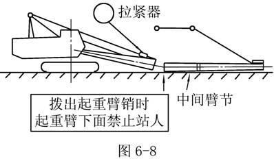
5. Remove boom joint pin for separation of boom foot and boom tip as shown in Fig. 7-8.
6. Move basic machine backward a distance where boom section can be put in between after lifting boom foot., as shown in Fig. 7-8.
Bridle Boom section
7. Joint the boom tip, boom sections and pendant rope together with pins.
8. Move the machine slowly to align the holes of boom foot and boom section. Then insert the pin.
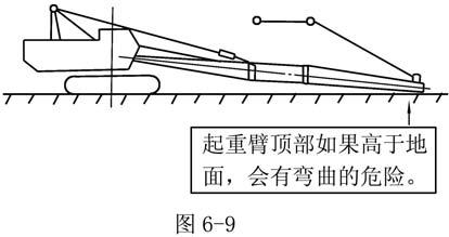
9. Wind up derricking rope until underside pin holes of boom foot match with boom section. Insert the pin as shown in Fig. 7-9.
Never enter under boom when drawing out boom pins Fig. 7-8 Do not take end of boom off ground or boom may bend.
10. Disconnect the bridle and the link of boom foot. Connect the bridle with pendant rope.
11. Install hoist rope, hook and wire electric devices.
12. Wind up derricking rope for working posture.
13. Gradually wind up the boom. Check the functions of boom over hoist preventive device and hook over hoist preventive device when the boom angle is 80°.
14. Check derricking rope has row on to winch drum properly.
7.3 Disassembly of Boom
1. Lower the boom slowly onto the ground. Put timber sleeper under the tip of the boom to protect it from damage or dirt.
2. Slack the derricking rope and remove the gay rope from the bridle.
3. Mount the bracket for self-assembling of the bridle on the basic boom with pins.
4. Support the basic boom with wood block.
Wooden block Support block
5.Wind and tension the derricking rope.
Caution: Tension the derricking rope. The boom top should not be away from the ground.
6. Adjust the position of support block to make no gap between basic boom and the wooden block.
7. Remove the underside joint pins of the boom. Wind the derricking rope a little and take out the block.
8.Lower the boom a little until whole boom is on the ground completely. Remove the spring pin on the upside pin.
Pull out the pin
Wooden block
Caution: The boom will fall off if it is supported with no blocks even though the bridle is connected with the boom foot. The boom will also fall off if disassembling it without tensioning the derricking rope.
Danger:It is absolutely forbidden to enter under the boom to pull out the connecting pins.
7.4 Jib Assembling
1. Before jib assembling, prepare the following component: pins for jib, cotter pin, hoisting rope, hook, supporting mast and pendant rope.
2. Put the boom onto the ground and install the jib and support mast.
3. Connect the upper gay rope to jib through the balance pulleys mounted on the supporting mast. Connect the lower guy rope to the bracket of the boom through the balance pulleys as follows.
Length of guy rope
A=16.487m
B=1.513m
C=19.441m
D=8.290m
Jib and guy rope connection:18mjib offset
Guy rope reeving with jib
CAUTION:
1. If the connection of the guy rope is not correct, the jib angle will be wrong and cause serious accidents.

2. Install the weight of hook anti-over hoist limiter when install the hoisting rope.
3. Adjust the Safe Load Indicator in accordance with the boom and jib combination and angle.
7.5 Assembly of the assistant boom
1.Prepare the parts for assistant boom and tools, such as hammer and spanner.
2.Lower the boom on the ground.
The position of stopper is shown as follows.
Guidepulleyfor assistantboom Stopper
Guidepulleyfor mainhoist
3.Adjust the stopper to move the assistant guide wheel to the center.
Stopper
4. Installation of the assistant boom a. Lift the assistant boom. Push the assistant boom towards the boom head to make the holes on the assistant boom align the holes on the boom tip. Insert Shaft 2. b. Turn the assistant boom to make the recesses which on the assistant boom fit the grooves on both sides of the boom tip. c. Install retaining plate 1 and 2 with bolts.
5.
Chapter Eight Wire Rope
8.1 Usage of Wire Ropes
Most of actions of the machine are done by wire ropes. The quality and the maintenance of the wire ropes effect on the efficiency of operation. Please use the ropes which appointed by the manufactory correctly.
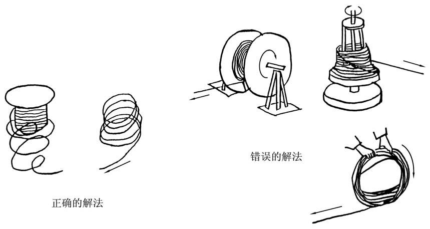
8.1.1 Unwind the rope from reel.
When install rope to the machine by unwinding a rope reel, correct procedure must be applied, as shown in Fig. 8-1.
8.2 Wire rope unwinds around drum
Unwinding a wire rope reel incorrectly will disturb the construction of the rope and cause loosening, kinking or twist which may seriously affect the servicing of the rope. Wind up new ropes onto the drum as shown in Fig. 8-2 and 8-3.
Comply with the following procedures when reel the ropes.
1. Lock the rope to the drum. Do not protrude the end of the rope beyond outer drum surface.
2. When reel the rope on a drum, use care to guide the rope in line with each other from one end of the drum.
3. When the first layer is finished, the rope should be tapped or pushed into place with a wooden hammer or pry bar to ensure an even winding surface.
4. Keep the gap as smaller as possible between the drum and the first coil of the rope when winding continuous.
5. Always keep sufficient tension when winding.
6. Winding in poor should be absolutely avoided, which is one of the reasons causes the premature break.
7. As a usual practice that the rope rewinding is necessary after a period of use, or it will run in poor occasionally.
8. Use rope clip to fix the end when handling wire rope with a rope socket as shown in Fig. 8-4.


8.3 Replace the Wire Rope
Servicing life of the wire ropes is greatly different depending on their separate working conditions. It is therefore very important that the wire ropes be inspected at regular intervals. Use defective rope is not allowed. All ropes including the hoisting ropes and pendant ropes must be inspected in regular intervals. Severe accident will be brought without inspecting the wire ropes strictly.
Replacement intervals of wire ropes are evaluated with their broken wires, wear and corrosive conditions.
Replace the wire ropes when:
1. Ten percent of the wires consisting of the entire strand are broken.
2. The diameter is reduced by more than 7% of its normal size.
3. Twisted or kinked.
4. The rope is deformed or rusted excessively.
In addition, such as the pendant ropes are subjected to shock and heavy loads, care must be paid for failure due to fatigue of materials. The replacement of a rope can be considered according to above conditions but inside conditions can not be estimated due to different working conditions. All in all, ropes should be replaced every 2000 servicing hours even if the above defects are not found.
8.4 Wire Rope Reeving
8.4.2 Main hoist wire rope reeving
Caution: The maximum number of part lines of main hook is 10. The direction of socket is shown in Fig. 8-6. The method of the rope reeving is shown in Fig. 8-7.
8.4.3 Aux. hoist rope reeving
See Fig. 8-8
Aux. hoist rope
Balance pulley
Sheave of jib support rod

Guy rope of jib
Joint with pins
Guy rope of jib
Sheave of jib tip
Aux. hoist drum
8.4.4 Reeve the wire ropes of main and aux. hoist at the same time.
See Fig. 8-9
Guy rope of jib Balance pulley
Sheave of jib support rod

Jib pendant
Joint with pins
Aux. hook
Main hook
Top of jib
Aux. hoist rope
Main hoist rope
Main hoist drum
Aux. hoist drum
Main and aux. hoist wire ropes reeving
8.5 Standard of Wire Rope
Specification for crane wire rope


