49 minute read
MAINTENANCE AND SERVICE

The 1 1st edition (April, 2013) edition (April,
Crawler Crane
For you
Our respectable users, thank you very much for choosing ZOOMLION crawler crane Before operating the crane, read these operating instructions carefully
Regular inspection, maintenance and service of crane are very important to make full use of crane performance, ensure crane safe operation and extend the service life of crane. Therefore, we offer you this Maintenance & service manual to facilitate your inspection, maintenance and service work.
This manual details the inspection, maintenance and service work to ZOOMLION crawler crane, and lists some common problem occurred and their solutions.
For safety’s sake, do not maintain the crane before you fully understand the contents in this manual, operating manual and other technical documents. If there is anything in this manual you do not understand, please contact local service engineer of Zoomlion, and they will provide you efficient technical support in time Any risks associated with unspecified and improper use are the sole responsibility of the crane’s owner, operator or user
Unauthorized person is not allowed to dismantle or adjust the hydraulic elements during maintenance. When the hydraulic system of crane fails or the components are damaged, please contact local service engineer of Zoomlion.
Our products and technical documents are subject to technical improvements and changes without notice. Therefore, please acquaint yourself with our updated technology information. If there are differences between illustration and product, refer to the product. If there is any question, please contact the local service engineer of Zoomlion
Special information
The following symbols appear in this manual:
Indicate an imminent threat or danger, which could lead to life-threatening or fatal injury of one or more persons.
Indicate a danger, which could lead to serious injury of one or more persons.
Indicate a potential danger, which could lead to slight or minor injury of one or more persons.
Indicate a danger which could lead to severe damage to the machine or other assets.

Indicate a tip or hint in the machine operating instructions.
Emphasize the importance of the information in operating instructions.
Is located wherever an action that could create a dangerous situation is prohibited.


1.1 General
This manual is compiled for crane maintenance personnel to carry out daily maintenance and periodic service. Read and understand the content in this manual before crane maintenance and service work.
Perform the crane maintenance and service work in accordance with the requirements stipulated in this manual, especially the information about , and
This manual does not include all requirements for maintenance and service. They are only for reference to help maintenance personnel to do the work. It is no substitute for official training.
This manual is compiled according to the working status of crane. However, it may be different from the actual status of crane due to technical improvements. Therefore, you can contact us if you want to know about more accurate information about the crane.
1.2 Product identification
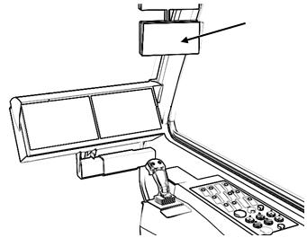
The crane name plate is located in a prominent position at the outside of cab. The following figure shows the detail position of name plate.
The user can distinguish this crane from the other via the name plate. The information on it is helpful for crane maintenance and service. Please keep it in a good condition within the service life of crane.
The serial number on the name plate is for crane identification. The users can confirm the crane components and relevant technical data by this serial number The serial number of this crane shown in the following figure is ZCC80-0001.
1.3 Illustration and symbols
This manual has a mass of illustrations, which are schematic. The meanings of illustrations are as follows:
Position of working mechanism to be operated

Sequence of operation
Correct operating way
Unpermitted or dangerous operating way
The illustrations in this manual may be different from the actual condition of crane However, this does not hinder the user from understanding the meanings of illustrations.
1.4 Hazard indicator
The content with respect to the safety is marked with “” , the safety instructions involved in the book are only the conventional contents
The following terms that are used in this manual “CAUTION” , “WARNING” , and “DANGER” are intended to point out certain important rules of conduct to all persons who maintain and service the crane.
Indicate a potential danger, which could lead to slight or minor injury of one or more persons.
Indicate a danger, which could lead to serious injury of one or more persons
Indicate an imminent threat or danger, which could lead to life-threatening or fatal injury of one or more persons.

2.1 Safety guidelines
Since various dangerous factors exist during maintenance and service of crane, the following are the safety guidelines for service technician to maintain and service crane superstructure and undercarriage. Read and understand these safety guidelines before maintenance and service work.
a) The maintenance work must be done by qualified personnel who have received training in crane technology, especially in electrical and hydraulic systems of crane.
b) The service technician must read and understand the operating manual, acquainting himself with crane and its operation.
c) Do not perform any maintenance work if the service technician is in low spirits, or he has drunk, or he has taken medicine which may affect the work.
d) No unauthorized personnel are accessible to crane during maintenance and service.
e) Make sure that the platforms, handrails, ladders and slewing table are free from dust, snow and ice.
f) The service technician must wear tight-fitting protective clothing when servicing the crane, together with the correct personal protective gear such as safety goggles, breathing mask for the particular activity g) Correctly use auxiliary equipment and set up working platform before performing high-level operation. h) Do not reach into moving drives or parts of the crane. The service technician must remove the ignition key and hang the “Prohibit” sign on the control device before operating these drives or parts i) Do not touch hot components, hot pipelines, hot liquid and engine when the engine just stops Only when the engine is cooled down for more than one hour, can the relevant maintenance work be carried out j) Depressurize all pipelines or containers before demounting the fittings or disconnecting the pipeline. Take preventive measures to protect personnel against injuries due to escaping hydraulic oil or air under high pressure. k) The customer must use original spare parts which meet with technical requirements, and must use standard components which comply with the technical standards in Spare Parts Catalogue so that the designed service life of crane can be fulfilled and the crane safety can be guaranteed. l) Cut off the grounding terminal of battery and turn off mast power switch before dismantling battery and welding operation on the crane.

2.2 Environmental protection disposal

Some harmful substances such as engine oil, lubricating grease, fuel, antifreeze coolant, hydraulic oil and refrigerant will be produced during maintenance. These substances and relevant things will damage the environment and people’s health, therefore, they must not get into the ground, into water or into the sewer system, and they must be recycled and disposed of according environmental protection regulations
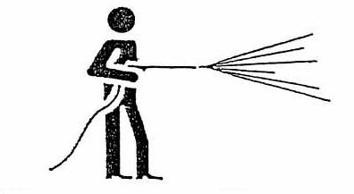
Dispose harmful substances according to the following regulations: a) The maintenance personnel must wear suitable protective gear such as protective clothing, protective gloves, safety goggles, breathing mask for the particular activity, since the polluted substance is corrosive and poisonous. b) When supply the crane with oil or lubricating grease which can pollute the environment, proper filling equipment such as refueling pump, oil filling device, hose, container and funnel must be used to prevent these substances from coming contact with the natural environment. c) Some lubricating oil may flow out when dismantling and changing the components Some oil may get into ground or into sewer system when changing oil. This will severely pollute the environment. Therefore, a proper container must be used to collect the waste oil and other waste materials. The refrigerant can not be released into the air d) The pollutant must be gathered together and preserved according to different categories for follow-up disposal, thus reducing the costs. During this time, take measures to prevent loss of pollutant. e) Use special container to move the pollutant from one position to another Ask specialized company to recycle the pollutant. Dispose of the waste materials according to relevant environmental protection regulations. f) If the pollutant comes into contact with the natural environment or person’s skin due to unexpected conditions, some emergency measures must be taken. If the pollutant falls down on the ground, collect it into a container to avoid it permeating into soil or sewer system. If the pollutant is sprayed on the skin, it must be rinsed away as quickly as possible with a lot of clean water In the event of eye injuries, use an eye-bath to rinse the eyes, and seek medical attention.
ZCC800HWG Crawler Crane
3.1 Description of main components
Tip boom
Main boom anchoring rods
Wire rope for hoisting winch 1
Wire rope for hoisting winch 2
Derricking pulley block
A-frame
Rear anchoring rods of A-frame
Main load hook
Main boom
Main boom tilting-back support
Auxiliary load hook Travel gear
Counterweight

The hydraulic system consists of main pump, triple gear pump, main valve, motor and so on. The pump-control hydraulic system is applied in the crane.
Traveling motor (L) Reducer
Hoisting winch 1 motor Reducer
Traveling motor (R) Reducer
Hoisting winch 1 motor
Reducer
Derricking motor Reducer
Slewing motor Reducer
Cooling motor
Control valve block
3.2.2 Arrangement of hydraulic elements in slewing table
3.3 Electrical system
3.3.1
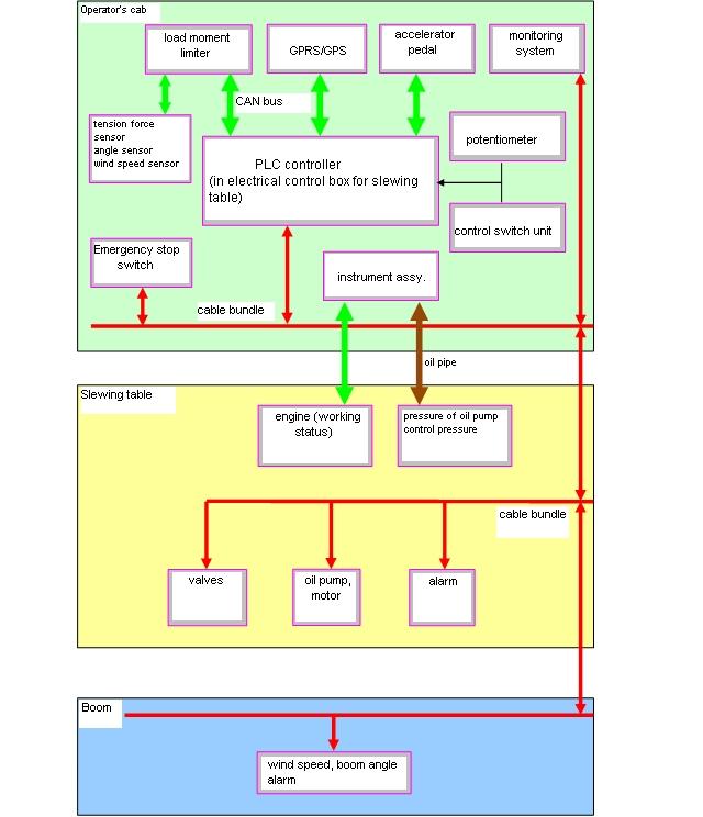
3.3.2 Arrangement of electrical elements in slewing table

4.1 General
A crane should be maintained regularly to ensure that it is always in a good state for safe use.
In addition to oil inspection and change, the maintenance work also involves frequent inspections to ensure that components are in good state
Appropriate workshop equipment shall be available for the lubrication and maintenance work.
The regulations and instructions in the Operating Manual for Crawler Crane shall be followed.
When being removed during the maintenance, safety devices should be reinstalled and inspected upon completion of the maintenance work.
Fuels, lubricants and replaced parts must be safely treated in compliance with the regulations for environmental protection.
4.2 Precautions
General precautions during the maintenance work are described as follows: a) Wear work clothes when conducting the maintenance. b) Put a crane on a firm and flat site and set a warning board marked with “Crane in inspection” c) Working at a position higher than 2m is considered as work at heights. Use ladders and safety belts in such a situation. d) Act in accordance with the commander's signal when moving a crane for maintenance. e) Prevent dusts and dirty articles from entering the hydraulic system which is in inspection or maintenance. f) If any items have to be maintained and adjusted immediately, maintain and adjust them immediately g) If repair is necessary, contact the local office of Zoomlion Mobile Crane Branch Company h) In order to ensure the performances of a crane, use the accessories and lubricating grease designated by Zoomlion. i) Replace consumables, such as filter elements, in time as specified to avoid faults. j) When any problems are difficulty to be determined in inspection or maintenance, contact the local office of Zoomlion Mobile Crane Branch Company.
To ensure safety, pay attention to the following points during the maintenance: l When a crane is in inspection and maintenance, drop the boom to the ground, stop the engine, lock the engine and remove the switch key to prevent other operators from starting up the engine during the inspection and maintenance work l Set up a warning board for the inspection and maintenance process. l Use the clean lubricating grease.
Failing to follow this instruction may cause personnel injury or death.
In inspection and maintenance, a warning board marked with “In Inspection and Maintenance, Please Do not Start it Up” should be set at the key switch.
Keep the rooms for storing the lubricating grease clean. Do not make dusts, water, or other things enter the vessels. Ensure that the lubricating grease is free of water l Keep the body clean. Clean the body with water to inspect for oil leakage, cracks, looseness of connectors, and other abnormalities. Especially, keep grease nipples, vent holes and dipsticks clean to prevent dusts from entering them. l Treatment of oil stains l Pay attention to fire prevention l Pay attention to the rotating parts l Pay attention to the water and oil temperature.
(2) Clean the steering wheels, central consoles, control panels, base plates, and the decorations in the stained cab only with the warm water that contains cleaning agents.
(3) Do not use corrosive cleaning agents.
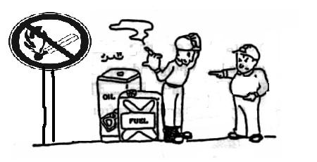
When fuel, hydraulic oil, lubricating grease are injected or changed, or filter elements are replaced, the oil might splash out. Therefore, wipe off the oil having splashed out in time to avoid fires. When cleaning the machine, do not spray water on the electric elements and connectors.
Put oil stained or other combustible stained garbage in safe places, and be familiar with the places of storing and methods of using the fire extinguishers.
When inspecting fan belts or pump, stop the engine in advance to avoid dangers of being caught.
It is dangerous to drain water, drain oil or replace filter elements when the engine is just stopped. For this reason, drain water, drain oil, or replace filter elements only after the temperatures have dropped. When the oil temperature is too low, the oil shall be heated properly (to the temperature ranging from 20 - 50 °C) before being drained l Inspect the drained waste oil and the old filter elements. l Prevent the intrusion of dusts l Clean joint surfaces.
When changing the oil or filter elements, pay attention to inspecting whether there are metal chips or foreign articles.

Protect the dismantled hydraulic oil pipes and hydraulic elements with plugs or seal covers against the intrusion of dusts.
After removing O-rings or other gaskets, clean the sealing surfaces, and replace the seal parts with new ones. When reassembling them, coat the sealing with a thin layer of oil l Pay attention to the internal pressure
When dismantling the pipelines, connectors or other relevant components with internal pressure, such as the hydraulic system, compressed air system, and fuel system, release the pressure in advance l Precautions for the welding process l Treatment of the waste oil l Unprofessional personnel are forbidden to servicing the cranes or replacing parts for them l Record inspection
Turn off the power, disconnect power lines of the batteries, do not apply a voltage of more than 200V successively, set the grounding within 1m from the welding points, and set no sealing or bearings between the welding points and the grounding points. Dismantle the load torque limiter or controller for welding around it to avoid damage.
Put the waste oil into the vessels and treat it as industrial emissions.
In order to learn about the correct working status of a crane and its components, perform regular inspections and recordings (Upon the use for the 1st time, use for the 1st time after a long-term out-of- service or maintenance, perform inspection according to the following requirements.).
For the record list recommended for inspection, see section 7.3.
4.3 Cycle description
All maintenance work is conducted intermittently and the interval is the maintenance cycle which is determined according to the operation status of the crane.
The maintenance cycle shall be subject to the following aspects: a) The specific operating time (hours) of functional parts of the crane b) The calendar time (date, month and year) when the crane is in operation and storage
In the maintenance of the crane, the maintenance cycle usually determined according to the first method and the special items are determined according to the second method.
Operation hours of the maintenance cycle refer to the operation hours of the engine, which can be read on the main display of the operator’s cab.
The maintenance cycle can be classified as follows according to duration of the interval.
4.5.1 Daily inspection of the engine
Inspect appearances of the engine’s components to ensure that all parts are intact and function normally
Items to be inspected: a) Inspect whether each part of the air suction pipeline is securely connected and free of breakage and leakage. b) Inspect whether the circulating cooling water way, the fuel pipeline and the engine oil are all free of leakage. c) Inspect whether the fan blades are free of damage and whether fan blades and other parts are not scraped. d) Inspect whether the belts are not worn or torn and whether their tensions are within in the normal range e) Inspect whether there is water or materials of the “sludge state” in the transparent glass cup of the oil-water separator f) Inspect whether installation bolts (screws) of the engines and its subsidiary systems are reliably tightened and free of looseness
4.5.2 Inspection of the engine operation status
Inspect the engine oil manometer, water temperature gauge, revolution counter and fault alarm indicator to make sure that the engine operates normally
Inspection steps: a) Start up the engine with the key switch and idle for 3 - 5 minutes. b) Accelerate the engine slowly to increase the rotational speed of the engine to about 1500RPM. c) Observe whether readings on the revolution counter change correspondingly during the acceleration. d) Read the values displayed on the engine oil manometer from the display screen, and the values are not less than 0.5bar in the idling process and not more than 6.5bar at the rated rotational speed. Inspection is required and repair is also required if necessary when the values are out of the ranges mentioned above. e) When the engine has operated normally for about 10 minutes, the water temperature readings on the instrument panel shall increase; if the engine has operated for 30 minutes and the water temperature still remains below 70°C, corresponding service is required. f) When the engine operates normally, it is normal if the alarm indicator of the engine does not flash.
(Note: For detailed operation methods, refer to the Operating Manual for Cranes.)
4.5.3 Maintenance of the engine
The engine shall be maintained according to requirements of the Operating Manual and Maintenance and Service Manual prepared by the engine manufacturer and provided together with the engine.
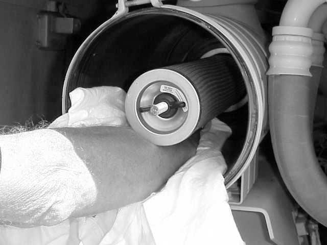
4.5.4 Cleaning of the air suction filter
When the engine is at the rated rotational speed, if the pointer of the air filter’s blocking indicator points at the read zone, it indicates that filter elements of the air filter are seriously blocked and need to be cleaned
Inspection steps: a) Loosen the bolts at tails of the air filters and dismantle the tail covers to pick out the external filter elements. b) Pat on the filter elements to shake off the dusts and dirt on the external filter elements. Connect the compressed air with hoses and blow the compressed air out to the filter elements until all dusts are blown away c) Install the external filter elements back into the air filter and install the tail covers as before. d) Nip the dust nozzle of the air filter open and knock on the shell of the air filter lightly to shake off the accumulated dusts e) Reset the air suction filter f) Start up the engine and stabilize the rotational speed to the rated rotational speed to confirm that the pointer of the blocking indicator points at the green zone. a) Shack off the dusts on the filter element b) Blow the compressed air over the filter element surface. c) Blow the compressed air over the filter surface. d) Clean the sealed supporting surface.
Do not damage the filter elements when cleaning the external filter elements. Do not clean the internal filter elements (safety filter elements). Do not clean external filter elements for more than 5 times.

Do not start up the engine during the cleaning work.
4.5.5 Replacement of the air suction filter elements
The external filter element must be replaced when it is cleaned for many times to avoid degradation of its filtering performance.
When changing the external filter element, replace the internal filter element (safety filter element) at the same time.
The replacement cycle for filter elements is 2,000 hours which will be shortened in the severe dust environment.
When changing the filter element, dismantle and install it in the method described in section 4.5.4.
Purchase the internal and external filter elements (safety filter elements and main filter elements) according to part numbers.
To ensure the quality of filter elements, purchase the filter element accessories from the basic machine manufacture.
4.5.6 Inspection of the cooling fluid level and supplementation of the cooling fluid
The cooling fluid (antifreeze fluid) of the engine might reduce continuously due to causes such as leakage and evaporation Severe lose of the cooling fluid will result in poor capability for heat dissipation of the engine, causing damages to the engine
Inspection of the cooling fluid level: unscrew the water tank cap to check the fluid level in the upper water chamber of the water tank, which shall be higher than 1/3 of the upper water chamber
Supplementation of the cooling fluid: unscrew the water tank cap and add appropriate cooling fluid into the water tank to make the fluid level between 1/3 and 1/2 of the upper water chamber
For requirements for performances of the cooling fluid, refer to section 6.1.
(1) Before adding the cooling fluid, stop the operation of the engine and make the engine cool naturally for a certain time.
(2) When unscrewing the expansion water tank cap, avoid getting burnt.
(3) Ensure that the added cooling fluid is the same as the original one.
4.5.7 Replacement of the cooling fluid
When the cooling fluid has been used for 2 years, it must be changed. Even though the engine has not operated for a long time, the cooling fluid also needs to be changed
Change steps: a) Put a proper vessel under the cooling water tank to collect the cooling fluid. b) Unscrew the water drain plug screw at the lower end of the cooling water tank to let the water flow into the collection vessel. c) Install the plug screw at the water drain hole and inject about 43L of cooling fluid in total from the water inlet of the water tank. d) Start up the engine and let it operate for several minutes to make the cooling fluid free of air bubbles before the fluid level is inspected again. For the change cycles of the cooling fluid, refer to section 4.4.
Do not drain the cooling fluid to the natural environment.
4.5.8 Inspection of the fuel pipeline
Items to be inspected: a) Each welding line on the diesel tank shall be free of oil leakage marks. b) Fuel hoses shall be free of leakage due to damages. c) Connectors of the pipeline shall be free of oil leakage. d) The diesel pump, injection nozzle, etc. of the engine shall be free of oil leakage. e) The accumulated water in the transparent shell of the oil-water separator shall be checked. In the case of much water accumulated in it, drainage is necessary Once leakage is found, corresponding maintenance treatment is necessary For requirements for the fuel quality, see section 6.3.
Use the approved fuel to extend the service life of the engine.
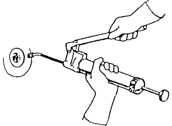
4.5.9 Drainage and discharge of the oil-water separator
The water contained in the fuel is separated in the oil-water separator and the impurities with a large particle size (more than 30 micrometers) are filtered and settled down in the water collection cup at the bottom of the oil-water separator to form the sludge. When the water is accumulated a lot, it shall be discharged outside to prevent it from entering the engine cylinder together with the fuel. When a lot of sludge is formed, it will increase the resistance to the fuel system, thus reducing the output power of the engine and even making it unable to start up the engine when it get serious.
ZCC800HWG Crawler Cranes
The drainage process is as follows: a) Put a proper vessel under the oil-water separator to collect the residual water b) Rotate the water drain valve at the lower end of the oil-water separator in the counter-clockwise direction to make the accumulated water flow out slowly c) When the diesel begins to flow out, rotate (close) the water drain valve in the clockwise direction until no diesel flows out
The discharge process is as follows: a) Disconnect the fuel tube between the oil-water separator and the fuel tank. b) Put a proper vessel under the oil-water separator to collect the fuel. c) Rotate the water drain valve at the lower end of the oil-water separator in the counter-clockwise direction to drain the fuel in it. d) Unscrew off the oil-water separator shell in the counter-clockwise direction with a special-purpose belt wrench with the sludge accumulated in the shell cleaned. e) When the water drain valve is closed, install the oil-water separator shell in the opposite direction and tighten it with the belt wrench f) Connect the fuel tube between the oil-water separator and the fuel tank. g) Open the outlet of the oil-water separator (unscrew the plug screw). h) Pump oil with the manual fuel pump and close the outlet when there is oil flowing out at the outlet. i) Continue pumping oil with the manual fuel pump and stop it until it feels heavy on the hands.
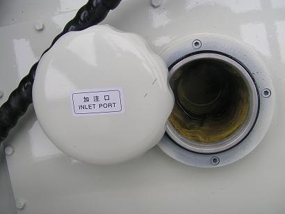
4.5.10 Cleaning of the fuel tank
When the fuel tank has been used for half a year, oil sludge and water will be accumulated in the fuel tank. In order to keep the fuel tank clean, the fuel tank needs to be cleaned.
The cleaning method is as follows: a) Put a proper vessel under the fuel tank. b) Unscrew the oil drain bolts at the bottom of the fuel tank to make the residual oil flow out. c) Dismantle the air filter over the oil tank and clean the filter screen. d) Clean the internal surface of the oil tank with brushes and then flush it clean with diesel e) Reinstall the plug screw of the oil drain hole at the bottom of the fuel tank as well as the air filter f) Inspect whether there is any leakage at the plug screw of the oil drain hole after the diesel is injected and whether the oil level is normally indicated on the main display. g) Install the cleaning cover for the fuel tank.
Treat the collected waste diesel according to relevant environmental regulations, and do not discharge it to the environment.
Take preventive measures to avoid fires when cleaning the oil tank.
4.6 Maintenance of the reducer
4.6.1 Inspection of the oil level
Inspect the oil level frequently. In the case of the oil level lower than the oil level mark, the gear oil shall be injected in time. In addition, the recommended gear oil shall be used according to different environmental temperatures.
Table × 4 - 003 Oil change cycle and oil change amount of each mechanism
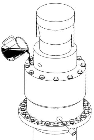
4.6.2 Change of the gear oil
When the gear oil is changed, it shall be changed again after the machine has operated for a long time. It shall be drained off when the oil is hot and special-purpose tools are required when the oil is injected a) Change of the gear oil for the lifting and derricking winch reducers
1) Unscrew plug screws of the oil drain holes at the lower ends of the winch reducers and those of the oil fillers at the upper ends of the winch reducers to drain the original gear oil.
2) Open the oil filling plug screw and clean the gear with the cleaning oil (warm and clean oil) to remove the abrasive matters and foreign matters.
3) Tighten the oil drain plug screw, insert the head of a hopper into the oil filler, inject the specified gear oil to the plug screw of the sight hole, and then stop injecting the oil when the oil level reaches the middle position of the plug screw of the sight hole.
4) Inspect the cleaning status and tighten the plug screw of the oil filler at the upper end
Inject oil after the plug screw is unscrewed.
When oil is injected, this plug screw at the sight hole shall be screwed to inspect whether the oil level reaches the cock hole edge b) Change of the gear oil for the slewing reducer
Drain oil after the plug screw of the oil drain hole is screwed.
1) Unscrew the oil drain rubber tube plug screw at the lower end of the slewing reducer and the screw plug of the oil filler at the upper end of the slewing reducer to drain the original gear oil.
2) Open the oil filling plug screw and clean the gear with the cleaning oil (warm and clean oil) to remove the abrasive matters and foreign matters.
3) Re-screw the oil drain rubber tube screw plug at the lower end, insert the head of a hopper into the oil filler, inject the specified gear oil to the plug screw of the sight hole, and then stop injecting oil when the oil level reaches the middle position of the plug screw of the sight hole.

4) Inspect the cleaning status and tighten the plug screw of the oil filler at the upper end
Unscrew the oil drain rubber tube plug screw
Inspect the oil level
4.6.3 Lubrication of bearings of the reducer
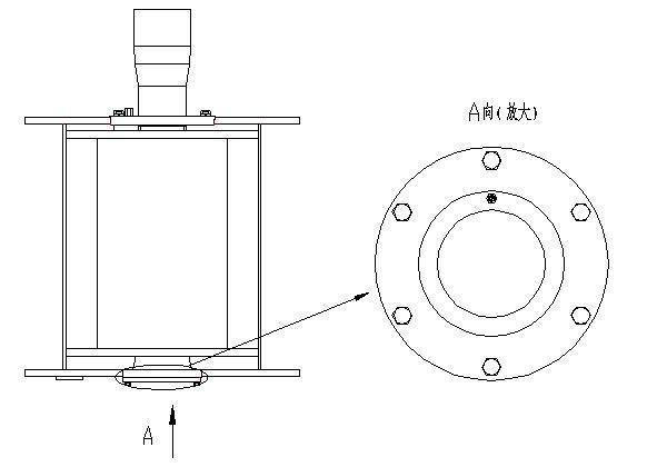
When the winch reducer operates every month or has worked for 200 hours, its bearings shall be lubricated with the lubricating grease injected with an oil gun
The oil cup for lubricating grease injection
Direction A (enlarged)
4.6.4 Inspection of brakes of the winch reducer
Inspect brakes of the hoisting winch reducer according to the following order: a) Start up the engine and make it operate at a slightly high idle speed. b) Apply a maximum load that the wire rope can bear to the corresponding hoisting winch c) Operate the control lever to make the hoisting winch 1 (2) lift the heavy objects up. d) When the heavy object is suspended in the air, push the control lever of the hoisting winch 1 (2) to the middle position and then make a mark at a certain place on the winch drum. e) Retain the heavy object suspended in the air freely for several minutes and then observe whether the position of the mark moves. In the case of no movement, it indicates that brakes of the winch reducer are good.
Inspect brakes of the derricking winch reducer according to the following order: a) Start up the engine. b) Pull out the oil tube at the brake cylinder of the derricking winch reducer. c) Operate the derricking erection action. d) If the holding pressure reaches the overflow pressure of the main pump and the derricking winch does not operate, it indicates that the derricking winch is effectively braked
Assign only well-trained professionals to inspect the brake of a winch reducer. Incomplete brake may cause accidents.

There are dangers of being dragged. When carrying out the maintenance, inspection and installation work, and exercise caution to avoid dangers of being drawn or dragged between the winch and the winch wire rope.
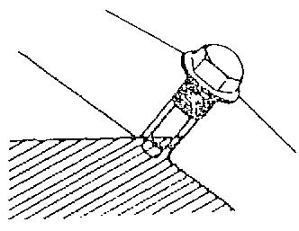
4.6.5 Inspection of securing bolts
Inspect whether securing bolts of the winch are loose. If they are loose, tighten them.
4.6.6 a) When the hoisting winch 1 with free-fall function cannot be braked, its brake strap shall be adjusted through its own adjusting nut and con-rod. Prior to inspection of the brake strap, rivets within the areas shown in the picture above shall be inspected. If rivets have been worn or are to be worn, the brake strap shall be replaced immediately. b) Brake straps of the hoisting winch 1 with free-fall function shall be inspected every week or after having worked for 50h. If rivets have been worn or are to be worn, the brake straps shall be replaced immediately
When selecting the hoisting winch 1 with free-fall function, inspect the brake straps.
4.7 Maintenance of the slewing ring
4.7.1 Routine inspection
a) Inspect the flexibility of the slewing ring. If noises, impacts and powers are found to increase suddenly, it shall be shut down for inspection, troubleshooting and overhauling when necessary b) Regularly inspect whether there are defects such as cracks or damages on the slewing gear ring, seizing, bite and peeling of on the gear surface. c) Frequently inspect the perfection of the sealing. If the seal belt is found to be damaged, replace it in time. If it is found to peel off, reset it in time.
4.7.2 Lubrication of the gear surface
Gear rings of slewing rings have been coated with the rust preventive oil before being delivered from the factory This rust-proof oil’s period of validity is usually 3 to 6 months Upon expiration of the period of validity, they shall be coated with the rust preventive oil in time. At the same time, it is forbidden to flush the slewing rings with water directly to prevent the water from flowing into the raceway
4.7.3 Lubrication of the raceway
Raceways must be injected with lubricating grease regularly according to the work environment. After having worked for 50h, raceways shall be injected with the lubricating grease. In special work environment, such as tropical belts, large humidity, many dusts and large temperature variation and having worked continuously, the lubrication cycle shall be shortened and the slewing ring must be injected with grease before and after a long-term placement.
The grease should be injected when the slewing ring operates When the lubricating grease flows over from the seal, it indicates that the injection is completed and the over flown grease will form a thin film to seal it.
4.7.4 Inspection of the slewing ring bolt
Requirements for inspection:
a) When the slewing ring has been used for 100 working hours for the 1st time, inspect the pre-tightening torque of the bolts for once. If more than 10% of bolts get loose, tighten them and then inspect them again at the 200th working hour b) Then inspect them every 500 working hours and the inspection interval shall be shortened under poor working conditions c) When the equipment has worked for 2,000 hours accumulatively, if a bolt has been loosened to less than 80% of the specified torque, replace this bolt and its two adjacent bolts. If 20% of bolts are found to get loosened to less than 80% of the specified torque, replace all the bolts. d) Usually, it is necessary to replace all bolts every 7 years or after having worked for 4,000 hours. e) When bolts are replaced, wipe them clean and then tighten them after coating them with the lubricating oil. The tightening torque shall be 1800N.m.
4.8 Maintenance of the crawler travel
4.8.1 Regular inspection
Insufficient lubrication of the connecting pin of crawler, improper tension degree of track pad, or smudginess on the crawler will cause noises and premature wear Therefore, inspect the crawler at intervals of less than one month before each work or after the crane has traveled for a long journey.
Items to be inspected: a) The wear of crawler traveling devices, lubrication of crawler pin, and tensity of track pad. b) The wear of the track roller or track carrier roller of the crawler, and lubrication of roller c) The wear of driving device, lubrication of reducer and smudginess of the crawler
4.8.2 Cleaning of the crawler
Clean the crawler when it is dirty The cleaning involves wiping off the dirt on track pad, sundries on the crawler carrier, and soil being mingled in between the drive sprocket or track roller and the track pad, etc.
4.8.3 Lubrication of the crawler pin
Put the crawler pin in a position that can be lubricated, and spray the crawler pin at joint with lubricant. Move the crane forward until the lower crawler pin is located on track carrier roller, and spray the crawler pin at this part with lubricant. You can also lubricate the crawler pin by daubing the waste oil
4.8.4 Tension of track pad
Before checking the tensity of track pad driving, the track pad must be cleaned. The tensity of track pad driving is estimated by its relaxation around 15 ± 5 millimeter, and the crawler components must be tightened or loosened subject to their tightness.
The tensity of crawler must be adjusted when the machine is on level ground. Slightly move the crane body forward before adjusting to concentrate the loose parts of the crawler on the top of drive sprocket, so that it can be easily adjusted.

Adjustment steps: a) Unload the bolts and shields from both right and left sides. b) Align the hydraulic jacks with the push rods respectively under nature state. c) Press the handle of the hydraulic jack slowly to move its driving axis and tension wheel forward, causing spacing between crawler frames and gaskets. d) After adjusting the crawler to appropriate tension, stop the movement of hydraulic jacks and fill in the spacing between crawler frames and gaskets with gaskets, and then mount the shield. After adjusting the crawler to appropriate tension, stop moving forward the tension cylinder. e) If the wear of pin hole on of the track pad is relatively larger, remove one track pad and tension it again when the track pad still fails to be tensioned after the tense wheel block reaches the end. f) Mount the shield
4.9 Maintenance of hydraulic system
To ensure that the hydraulic system is in a good status for long-term operation, maintain the hydraulic system on time.
4.9.1 Routine inspection of hydraulic system
For the inspection period of hydraulic system, see the following table.
Note: The sign indicates initial replacement. The sign indicates that the ☆★ inspection is required. The▲ sign indicates periodic replacement.
4.9.2 Inspection of the oil level of the hydraulic tank
The level of hydraulic oil must be checked every 8 hours, and the status of hydraulic oil is inspected as described the following table.
Table ×
4 - 005 Decision of hydraulic oil status
Mixing of foreign objects
Dust and metal powder from outside
Test tube (transparent) and fresh hydraulic oil
Appearance comparison
In the state of starting up the engine, take the sample from hydraulic oil tank or pipeline, and compare it with fresh oil for its turbid condition
Water
Test tube or transparent containers, fresh oil
Appearance comparison and heating estimation
Oil within the hydraulic oil tank becomes opaque Heat up the opaque oil sample to see the settled water at the bottom. Take out the opaque oil sample and insert the red-hot bar iron. Then sizzle is generated. Dropping the opaque hydraulic oil on a heated iron plate will also sizzle. Before starting the engine, unscrew the oil drain valve of the hydraulic oil tank. Take out the oil sample, and then observe the subsidence situation of water
Degradation
Test tube or transparent containers, fresh oil
Appearance estimation and sensation estimation a) Before starting the engine, check the oil level in the hydraulic oil tank. The level displayed on the liquid level meter below the visual position indicates insufficient hydraulic oil of the hydraulic system. Fill the hydraulic oil till it reaches the visual position, and then start the engine. b) If the oil in the oil tank reduces fast, check the hydraulic pipelines and elements, find the leak position, and stop the leakage before starting the engine c) Over temperature (above 80 °C) of hydraulic oil will accelerate the degradation of hydraulic oil and shorten the service life of hydraulic elements. Low temperature (below 20 °C) indicates that the flow of hydraulic oil is poor, and an overhasty operation may damage hydraulic elements. Therefore, after starting the engine at low temperature, preheat it to make the temperature of hydraulic oil reach around 20 °C. d) Refer to the following table for the inspection after starting the engine
Take the oil sample from the hydraulic oil tank or the pipeline, inject it into the container, and compare its color and odor (smell) with the fresh oil. Oxidation and deterioration oil will turn to black brown, and badly degenerative oil will stink.
Table × 4 - 006 Inspection after starting the engine
Remarks
Hydraulic oil cannot be used permanently Therefore, it must be inspected and replaced in accordance with whether impurities have been mixed into the hydraulic oil or the degradation degree.
4.9.3 Replacement of the return filter
A signal on the pressure switch of a filter element of the return filter indicates that the filter element is blocked. In such a situation, replace the filter element.
a) Unscrew the filter cover (cleaning cover) of the return filter, and replace the filter element or refuel the oil tank. Set two M18*1.5 oil ports at the filter head, and install the pinger at any part.
b) Replace the filter element of the return filter every 500 hours, with the initial replacement subject to 50 hours
☞ Cleaning cover of return filter, unscrew and replace the filter element.
When replacing the filter element, do not install it reversely to avoid serious consequences.
4.9.4 Replacement of the air cleaner

In hydraulic system, the air cleaner of oil tank needs to be checked on time subject to every hydraulic oil adding for the hydraulic system Inspect the hydraulic system, clean the dirt on it in time, and replace the damaged one if any
4.9.5 Cleaning of the filter element
Inspect the filter, find the dirt on it, and then clean the filter in time.
Steps for cleaning: a) Take out the filter with a special-purpose wrench b) Clean the filter element with dedicated cleaning solution or clean diesel
4.9.6 Change of the hydraulic oil
Before delivery, the hydraulic oil tank of this product is filled with 800-liter hydraulic oil whose oil grade is GB11118.1-94 L-HV32, L-HM46, L-HM68, or HS 0358-95 aviation hydraulic fluid 10# subject to the regional work.
Inspection and replacement cycle of hydraulic oil:
The normal replacement cycle for hydraulic oil is 2,000 working hours. If it is obviously dirty, replace it immediately regardless of the running time. Inspection items and replacement cycle for hydraulic oil are as follows:
Table
× 4 - 007 Inspection items and replacement cycle for hydraulic oil
Oil level inspection of hydraulic oil:
Check the oil level when the crane is traveling. The liquid thermometer is provided with scales through which you can check the temperature of hydraulic oil and the oil level
The lowest oil level line is the “0 °C” scale mark. Thus, an oil level of lower than “0 °C” scale mark indicates that the hydraulic oil should be supplemented.
Oil change steps: a) Drain the hydraulic oil in oil tank. b) Dismantle the general return oil pipe, clean the oil tank and filter carefully Specifically, clean the oil tank and filter with the chemical cleaning agent whose solid contamination degree does not exceed 18/15. After cleaning and airing them, clean them with fresh hydraulic oil whose solid contamination degree does not exceed 18/15. c) Drain the flushing oil and fill in fresh hydraulic oil again. d) Start the engine, run the engine in low velocity to energize the oil pump. e) Manipulate each mechanism respectively and drain the used oil of each loop of the system one by one on the basis of fresh hydraulic oil. The used oil drained cannot flow into the hydraulic oil tank. f) Stop the oil pump when there is fresh oil flowing out from the general return oil pipe g) Connect the general return oil pipe with oil tank and set each element to initial working state at last h) Supplement hydraulic oil for the oil tank until it reaches the visible window of the liquid level meter of hydraulic oil tank

Precautions for replacement: a) Do not use the hydraulic oil for more than 24 months. b) Filter or replace hydraulic oil in time upon heavily contaminated hydraulic oil. c) Select appropriate hydraulic oil in accordance with the ambient temperature. d) Do not mix the hydraulic oil of different grades. e) When changing the oil, flush all of the original oil, and do not allow sundries like sand and dirt entering the oil tank. f) When changing oil at each loop, constantly add fresh oil into the hydraulic oil to avoid empty oil pump g) When starting the engine at cold areas, ensure that the minimum temperature for starting is reached, and start the engine in no-load state. After the temperature of the no-load system reaches the minimum temperature required for running, slowly apply load to the system, and keep the system running at the temperature on the minimum load.
4.9.7 Cylinder inspection
Check for the oil leakage at the installation oil port and nearby pipelines of each hydraulic oil cylinder, and the scratches on the extension of piston rod.
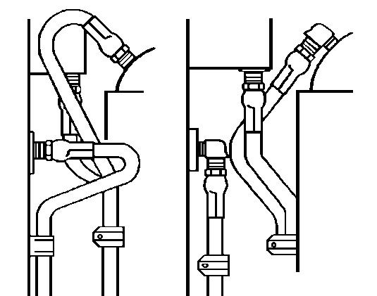
4.9.8 Installation of the pipeline
When installing a hydraulic pipeline, pay attention to the following items: a) Avoid distortion of a hose. b) Ensure sufficient radius of bending. c) Use elbow and other connectors when necessary d) Allow certain looseness to offset the shrinkage of the hose under pressure. e) Ensure fixed position of a hose with a clamp.


4.10Maintenance of the electrical system

4.10.1 Inspection of the lighting system
Check for normal operation of the illumination system.
As shown in the figure on the right (e.g.: aviation lighting devices)

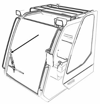
4.10.2
Inspection of windshield wipers in the operator's cab as well as cleaning solution
Check for normal operation of the windshield wiper weekly.
Location of sprayer is at the left rear side of the cab seat. Add water into the sprayer constantly, and add a little cleaning agent when necessary
4.10.3 Inspection of the video monitoring system
The monitor system is optional If the monitor system is equipped, check for normal operation of the monitor system camera and the definition of LED image in the operator’s cab before using vehicles.
4.10.4 Battery inspection
Batteries must be well maintained and kept for use, because they function as the power supply of starting the engine, electrical control system, illumination and electrical auxiliary devices of the machine.
a) Store the battery (a filled and charged lead-acid battery) at the temperature ranging from 5 °C to 25 °C and in a dry, clean and ventilated environment. Do not expose the battery to direct sunshine to avoid degradation of the performance caused by high ambient temperature.
b) Do not inverse and place the battery horizontally. Do not shock and press the battery mechanically c) Recharge the battery in time to avoid performance degradation caused by the sulfating of the battery d) Do not overcharge the battery Avoid premature failure of the battery caused by too much water loss, growth of grid and drop of diachylon. e) Remove the batteries from the car and store them in a well-ventilated and dry place if they are used for long time (usually more than 15 days). Charge the batteries every 3-6 months (see if the indicator is black or not).
This series of lead-acid batteries for cars is the dry charged batteries produced in accordance with JIS Japan and DIN Germany Dry charged batteries can start the car in 30 minutes after injecting the electrolyte. If possible, charging for 3 - 5 hours before use will result in a better starting performance.
Preparation before use: a) Make sure the level of electrolyte is 10 mm higher than the minimum waterline b) Make sure the blow cock is crewed in case of acid leakage. c) Check the air hole of the blow cock to ensure a smooth venting. d) Pay attention to the positive and negative poles when connecting wires to avoid reverse connections
Storage and maintenance: a) The storage battery should be stored in a clean, dry, and ventilated storeroom at ambient temperature ranging from 5°C to 40°C. Be sure not to unpack the sealing bar or blow cock of the dry charged battery before use. b) Under exceptional circumstances, the storage battery should be stored in company with electrolyte and be charged monthly through common charging method. The liquid level and density of electrolyte should also be regulated as required, and the density of electrolyte is 1.28±0.01g/cm3 c) Do not prepare the electrolyte with river water, well water or water containing impurities. When using a battery, keep the external and wiring of the battery dry and clean. d) After discharging battery, charge it in time to avoid long-term idleness. e) Open the blow cock while it is charging and screw up the blow cock before use. f) Do not smoke and light fires at the charging site.
Exterior charging is required under the following circumstances: a) The density of electrolyte falls to 1.170 and below b) Brownout. c) Under-voltage, the voltage of the battery is under 0.8 V
4.10.5
Inspection of the limit switch
Provide references for crane operators by real-time monitoring the working condition of the crawler crane, and displaying the condition on the moment limiter In abnormal working condition, the crawler crane generates an alarm by an icon flashing on the system display interface, and interrupts the operations that could increase the danger
1 Hoisting winch 1 over-winding alarm
Over-winding of the hoisting winch 1 is also known as the main hook reaching the upper limit. By this time, the corresponding alarm indication “ ” blinks in the display, along with audible alarm. Meanwhile, the “reel in” movement of hoisting winch 1 and “reel out” movement of derricking winch will be cut automatically, and the bypass key switch operation is effective
2 Hoisting winch 1 over-release alarm
Over-release of the hoisting winch 1 is also known as only three circles of wire ropes left on the hoisting winch 1. By this time, the corresponding alarm indication “ ” blinks in the display, along with audible alarm. Meanwhile, the “reel out” movement of hoisting winch 1 will be cut automatically, and the bypass key switch operation is effective
3—Hoisting winch 2 over-winding alarm
Over-winding of the hoisting winch 2 is also known as the auxiliary hook reaching the upper limit. By this time, the corresponding alarm indication “ ” blinks in the display, along with audible alarm. Meanwhile, the “reel in” movement of hoisting winch 2 and “reel out” movement of derricking winch will be cut automatically, and the bypass key switch operation is effective.
4 Hoisting winch 2 over-release alarm
Over-release of the hoisting winch 2 is also known as only three circles of wire ropes left on the hoisting winch 2. By this time, the corresponding alarm indication “ ” blinks in the display, along with audible alarm. Meanwhile, the “reel out” movement of hoisting winch 2 will be cut automatically, and the bypass key switch operation is effective
5 Main boom 80° alarm
When the elevation angle of the main boom reaches 80° , and limit switch at the root of main boom is closed, the corresponding alarm indication “ ” blinks in the display, along with audible alarm. Meanwhile, the “reel in” movement of derricking winch will be cut automatically, and the bypass key switch operation is ineffective.
4.10.6 Inspection of cable terminals and dust guards
Every dismantling of the basic machine and site transport requires the inspection for whether the cable terminal is aligned and plugged tightly and whether the dust guard is well covered.
4.10.7 Prevention of electrical parts or cables from catching fires
Fire of the electrical parts or cables can be prevented, and effective measures can be taken to avoid such danger
Precautions: a) Inspect or exam the electrical devices of the crane regularly. Find out the cause for faults like loose connection and cable heat, etc., and troubleshoot these devices immediately b) Check all cables, connectors and terminals for looseness or damages (see if there is any oxides formed on both poles of the terminal or battery), and rectify all confirmed faults immediately. c) Use the original spare parts and original fuse in compliance with the specified rigidity only d) Close the crane immediately in case the power fails e) No unauthorized replacements, supplements or modifications toward the electrical system are allowed unless approved by the manufacturer
4.11Maintenance of hooks and pulleys

Since the service condition of the main hook varies from day to day, inspection is required every day (starting with duty shifting). Pay attention to observe any defect that could affect the security before and in the process of the operation.
4.11.1 Daily maintenance of hooks
Daily inspection and maintenance involve the following items: Wipe the main hook clean.
a) Lubricate the pulleys, rotating parts and other parts with the grease nipples.
b) Inspect all bolts and screws, and make sure all cotter pins are complete and the openings are opened.
c) Check for the uniformity of pulley race and rim wear, the matching of wire rope and pulley race and looseness or shaking of the pulley.
d) Make sure that the rotating part of the hook moves freely and the spacing is not large. Any feeling of difficulty or jamming requires the inspection for bearing and shaft sleeve damage or insufficient lubrication.
e) Inspect the overload damage of the main hook.
f) Inspect the elongation of side plate, extension of bore diameter, and bending, elongation or cracking of bolt g) Inspect the safety catch.
4.11.2 Pulley inspection
Check all pulleys for damages like fractures, diagonal plane or similar damages. Scrap or replace the pulleys immediately upon the following damages: a) Cracks, rim damages or relatively serious wear b) The wear extent of the pulley groove wall reaches 80 % of the original wall thickness. c) The wear extent of the pulley groove bottom exceeds 25 % of the diameter of the wire rope. d) Other defects that damages the wire rope.

Pulley groove must be larger than the diameter of the wire rope. Too thick a wire rope will fracture the rim of pulley and increase the wear of the wire rope and the pulley
4.11.3 Inspection of rolling bearings on the pulleys
The following inspections are conducted annually for all pulleys: a) Surplus of grease b) Sealing socket for bearing c) Running noise and rolling resistance.
The corresponding rolling bearing must be replaced in case defects are detected.
4.11.4 Replacement of rolling bearings
We suggest a maximum running of 1,000 hours or replacing all the rolling bearings of pulley in every 5 years.
4.11.5 Pulley lubrication
Each pulley has only one oil filling nozzle. Before the pulley lubrication, wipe the nozzle, clean and inject the grease with grease gun until the fresh grease overflows from the end face of bearing.
4.11.6 Inspection of the safety catch
The safety catch must be complete and undamaged so that it can limit the loose lifting slings and other lifting devices on the hook.
Safety catch cannot bear the load. Therefore, lifting slings and other lifting devices cannot be hung on the safety catch.
4.11.7 Inspection of each hook body
The hook body must be inspected at least yearly using liquid penetrate test, magnetic particle testing, ultrasonic flaw detection or X - ray inspection, etc.
Deformation inspection
Wear/crack inspection
Check the hook for deformation, local cold deformation and extrusion, crack, wear and rust of clamping jaw Lock the joint of hook nut
Deformation: The hook must be replaced if the falcula has increased more than 10 % in comparison with the original size “y” The original size “y” is recorded on the hook. Conduct measurement one by one.
Corrosion: Check the thread and shaft being operated for corrosion and wear
Therefore, unscrew the hook nut on shaft
If reprocessing is required to remove the corrosion, such process should not make the diameter of the threaded core exceeds 5 %, otherwise the hook must be replaced.
(1). Do not use the hook with defects.
(2). Do not repair the hook by welding.
4.12 Maintenance of wire ropes
4.12.1 Cleaning of wire ropes
For dirty wire ropes, their external surface should be cleaned frequently Especially, for the wire ropes that are used in a corrosive environment or near chemical substances, dirt on the surface should be removed in time.
4.12.2 Lubrication of wire ropes
The manufacturer has sufficiently lubricated wire ropes during manufacture to prevent corrosion and reduce friction between wire rope strands, wire ropes and pulleys, and wire ropes and drums.
When black spots or rust exist on the surfaces of wire ropes, the wire ropes need secondary lubrication. Timely secondary lubrication plays a positive role in extending the operating life of wire ropes The lubricating oil for secondary lubrication can hardly penetrate and flow into wire ropes, so it should not be applied excessively Excessive lubricating oil will stay on the surface of a wire rope, making the check for wire rope fracture relatively difficult. It would be best to adopt acid-free grease as the lubricating oil and the grease should be heated and diluted before utilization.
Lubricating oil should be applied by the following means:
By brush
4.12.3 Inspection of wire ropes
By cotton yarn By cotton yarn
The working life of a wire rope is different based on the operating condition of the machine. Wire ropes for both lifting and derricking must be strictly inspected regularly to find abrasion and damage in time.
Parts to be inspected: a) Overall length of a wire rope; b) The part which bends most frequently on a pulley or drum; c) The parts which bend on pulleys or drums at the moment when load is lifted; d) In the multi-layer winding system, the part where a wire rope contacts a drum flange, and the transboundary zone where the upper wire rope crosses the lower wire rope.
Inspection interval
It is recommended to inspect whether damage exists on wire ropes and ending joints. For the beginning weeks after new wire ropes are installed and the fracture occurs for the first time, the inspection interval is shorter than that in other time periods. When overload occurs or suspicious damage which can not be seen is detected, the inspection interval should be shortened accordingly
In addition, when operation ceasing duration is extended and the wire rope transmission gear is re-installed, or when winch equipment is disassembled and re-installed at a new location, or when an accident happens or damage exists during the operation of wire ropes, the inspection must be performed.
4.12.4 Replacement standards of wire ropes
Wire ropes are always damaged as a result of the combination and accumulation of kinds of factors. The executive staff should judge the cause and decide whether the wire rope should be discarded or be used continuously a) Fractured wire: In case more than 10% of the single wires (excluding filling wires) of a wire rope within one lay length fracture, for the wire rope with multilayer strands (typical multi strand structure), fractured wires mainly exist inside, making such fracture “invisible” . In case lubrication at any local position becomes dry or deteriorated, special attention should be paid; b) Fractured line: In case fractured wires exist at or near the end of the rope, even in a small number, it indicates that the stress at such position is great. If the length of the rope permits, the position of fractured wires should be cut out and re-installation should be performed properly; c) Local aggregation of fractured wires: In case fractured lines cling together and aggregate in the range of the rope length less than 6d (d: diameter of wire rope) or exist almost in one strand, even though the number of fractured wires is small; d) Increase of fractured wires: Fractured wires would appear after a wire rope has been used for a period of time, the number of fractured wires will increase gradually, and the interval will be shorter and shorter. e) Abrasion: Abrasion reduces the sectional area of a wire rope resulting in lower strength; when the external wires are abraded to 4% of its diameter, or when the diameter of the wire rope is reduced by 7% compared with the nominal diameter; f) Fracture of rope strands: In case an entire rope strand fractures, it is caused by the damage of rope core resulting in reduced rope diameter; g) Reduction of elasticity: Rope diameter reduces, the lay length of a wire rope extends, parts press tightly against each other and space between wires and between ropes is inadequate These phenomena indicate the reduction of elasticity At this moment, although no fractured wire exists, the wire rope is obviously difficult to be bended, which may abruptly break and should be discarded immediately; h) Corrosion: When severe corrosion occurs at inside and outside of a wire rope; i) Distortion: Distortion of wire ropes are disposed of by the following means:
For the damage of a wire rope, inspection personnel should firstly investigate whether it is caused by the defect of equipment, and if so, such defect should be eliminated before the wire rope is replaced.

Whether the wire rope should be replaced may be decided based on the following factors. Refer to relevant Chinese National Standards (GB/T 5972) and ISO standards (ISO 4309).
× 4 - 008 Disposal of distortion of wire ropes Wave
In case of d1≥4d/3, with the length of a wire rope not more than 25d, the wire rope should be discarded as useless, where d is the nominal diameter of the wire rope; and d1 is the envelope diameter after the wire rope distorts
Cage distortion
Strand extrusion
Single wire strand extrusion
Multiple wire strands extrusion
Discard as useless immediately
Discard as useless immediately
Discard as useless in case distortion is severe
The diameter of rope increases at some positions
The diameter of rope reduces at some positions
Part positions are flattened
Discard as useless in case distortion is severe
In case the diameter of rope increases greatly at some positions, the rope should be discarded as useless without delay
In case the diameter of rope reduces greatly at some positions, the rope should be discarded as useless without delay
Discard as useless in case the flattening is severe
Twist
Bending
Discard as useless in case the flattening is severe
Discard as useless immediately
Damages caused by the action of heating or electric arc
4.13 Maintenance of air conditioning equipment
4.13.1 Daily maintenance
Discard as useless in case of any color change a) Regularly inspect the refrigeration equipment of the air conditioning system, especially check whether pipe joints are loose, whether oil stains exist at the oil seal of a compressor, and whether coupling screws are loose. If any, repair should be performed in time; b) Regularly inspect wire joints to prevent looseness and exfoliation and avoid accidents; c) Regularly remove dirty, sundries, etc. from the cooling fin of the condenser to maintain a good heat dissipation effect; d) Keep the air interchange outlet unimpeded and do not put any substance at the air outlet to prevent air circulation from being impacted which will lower the evaporability of the evaporator and the refrigeration effect. e) Observe whether refrigerant is charged properly via the liquid window of the reservoir (when the environment temperature is 30-35 °C, and the engine speed is 1,600-1,800 RPM).
4.13.2 Off season maintenance
After the off season of air conditioner (winter) comes, air conditioners should be started every week and operate for ten minutes to make refrigerant circulate so as to prevent refrigerant leakage caused by dry shaft seal of compressor to keep the compressor in a good condition and prevent such components as expansion valve, etc. from rusting When summer comes each year, the assembly of refrigerating system should be comprehensively inspected, cleaned, checked for leakage and refrigerant should be applied to ensure normal operation of the refrigerating system.
4.13.3 Contents of regular inspection and adjustment for air conditioners
Table × 4
-
009 Contents of regular inspection and adjustment for air conditioners
Inspection items Content Time
Piping joint
Inspect the looseness and damage conditions of pipelines and pipe joints, and whether oil dirt exists on pipe joints. Oil dirt indicates microscale leakage, and repair should be conducted. Weekly
Condenser Inspect whether dust and muddiness exist on the cooling fin, and high pressure water should be utilized for washing if necessary Weekly
Evaporator cooling fin Inspect whether cleaning dirt exists and utilize compressed air to blow off it
Compressor Inspect the oil level of compressor and replace refrigerant oil
Pressure of high & low pressure ends Check the pressure of high & low pressure ends
Electrical components Inspect, and adjust if necessary
Once a quarter
Once two quarters
Once a quarter
Once a quarter
Once three quarters Assembly parts Inspect whether bolts of assembly parts are loose, and if any, fasten them
Blower Inspect the operation condition of blower, charge lubricating oil and no abnormal sound should exist on components during operation
4.14 Maintenance of the lubricating system
Once a quarter
The basic machine lubricating system is a manual lubricating system, and lubrication needs to be completed manually by an oil gun.
Precautions for oil filling: a) Mineral high quality grease which is pressed into oil gun or utilized mainly to lubricate equipment should not be liquefied when temperature raises and should not condense under freezing point; b) Lubricating grease with the same grade is required to be utilized, and it is forbidden to utilize grease of different grades.
Before grease (lithium-based grease) is charged, the grease nipple should be wiped to be clean.
4.14.1 Grades of lubricating grease
Table × 4 - 010 ZL-2 and ZG-3 lubricating grease recommended by our company
4.14.2 Injection method
Daubing or injection by oil gun
4.14.3 Injection position and cycle
Lubrication and maintenance for lubricating positions should be performed regularly to ensure good operation of equipment.
4.14.3.1 Basic machine
The basic machine includes superstructure and lower structure. Lubricating points and cycle are shown in the following table and figure:
Table × 4 - 011 Super and lower structures lubricating grease injection table
Every hours
Every
Every
Every
Each month or 200 hours
According to service conditions
Each week or 50 hours
Every day or 10 hours
(1) Before oil filling, wipe the oil cup and the surface where oil is to be applied to make them clean.
(2) Lubricating grease should be also applied regularly for the sliding surface which is not listed in the table.
(3) Lubricating grease with different grades should not be mixed to each other
(4) For bush, axle and bearing, lubricating grease should be injected till the original grease is extruded.
(1) Shut down the engine before lubricating.
(2) When one climbs a crane, it should be ensured that the ladder, platform and railing are clean and dry, and he should wear safety belt to avoid high-altitude falling resulted from wet and slippery conditions.
(3) Running counter to this stipulation may cause severe casualty.
4.15 Appearance inspection for structure components
Structure members are the bearing components of basic machine, hence structure work inspection is necessary to be performed.
Recommended inspection cycle: a) Normally, inspection should be conducted once half a month or a month. b) When load of lifting operation ≥ 90% of the rated load, inspection should be performed once respectively before and after the operation. c) Experts must be invited each year to inspect the anchoring rod once
Inspection items: a) Crack b) Distortion
The straightness tolerance of the main chord member of boom section shall be in line with the attached table, and the straightness tolerance per meter of the web member of boom section shall not be greater than 1.5mm.
Method to test boom section chord member straightness u Local straightness of chord member
As shown in the figure, put a 1-meter ruler close to the boom section chord member from two directions with an angle of 90° , and the difference between the maximum space and the minimum space between the ruler and the pipe wall should not be more than 2mm.
u Overall length straightness of chord member
As shown in the figure, arrange a φ0.49 - 0.52 mm wire rope along the direction of length outside the chord member and 30mm away from the pipe end, with the tension as 147 N.
Measure the horizontal distance from the wire to the chord pipe. The difference between the maximum and the minimum should be in line with the requirements of Table × 4 - 013.
Turn the boom by 90°, and repeat the above test for the same chord member
4.15.1 Turntable inspection
Key inspection position: a) Lug connecting to the boom, A-frame rear anchoring rod and front A-frame; b) Counterweight hanging point; c) Base plate connecting to the slewing ring; d) Joints of left & right wallboards and upper & lower cover plates; e) Reinforce the joints of U-bar and left & right wallboards (upper & lower cover plates).


4.15.3 Boom inspection
Routine inspection: a) whether the rope support of boom head rotates smoothly; b) whether the boom pin spindle, anchoring rod and spring bolt are damaged or come off; c) whether the phenomena of peeling and coming off exists on boom paint; d) whether the structure member distorts; e) whether the structure member possesses any crack; f) Other abnormities.
Corrosion prevention and lubrication: a) Paint surface: painting make-up should be performed based on needs; b) Mating surface: apply lithium-based grease.
(1) Before injecting lithium-based grease, wipe the grease nipple to make it clean;
(2) Before painting make-up, clean the surface.

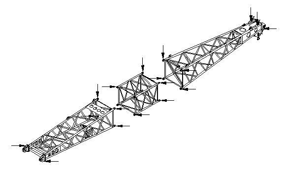

4.15.4 Anchoring rod inspection
Overall length inspection must be performed for the anchoring rod when installation and connection are conducted including the hidden surface and inner bores. The positions of anchoring rod needing inspection are shown in the following figure.
Contents to be inspected include: a) Inspect whether any crack exist on the anchoring rod
1) Regularly inspect whether any crack exist on the anchoring rod;
2) The surface crack test should be conducted for at least yearly, such as magnetic particle testing;
3) In case any crack is found, the anchoring rod must be replaced in time; b) Inspect the length of the anchoring rod c) Inspect the abrasion of anchoring rod d) Inspect the paintcoat of anchoring rod e) Inspect the plastic deformation of anchoring rod
4) In case any bow A-frame possesses cracking welding line, it should be replaced in time.
Do not perform repair work.
The length of anchoring rod must be measured to inspect the extension of the anchoring rod. The maximum allowable extension of the anchoring rod is 0.2% of the original length. For example, for the anchoring rod with the length as 5700mm, the maximum extension is 11.4mm.
For the original length of each anchoring rod, please refer to Maintenance and Service Manual for ZCC800H Crawler Crane.
Inspect whether any abrasion trace exists on the anchoring rod pin hole and connecting pin spindle, including the spring bolt which is utilized to fasten the pin spindle.
Regularly inspect whether corrosion and coming off exist on the paintcoat of anchoring rod, and in case of any corrosion pit, paint in time.
Inspect whether the anchoring rod possesses twist, and in case of any twist, the anchoring rod should not be utilized any more and should be replaced without delay
Inspection cycle:
Inspection should be conducted based on the conditions of operation area and the actual operation situation. If utilization is frequent, the inspection cycle should be shortened accordingly, and experts must be invited annually to conduct inspection for anchoring rods.
In case the damages described above exist, replacement must be performed immediately. An anchoring rod with any defect will cause a severe accident.