4 minute read
Every 250 Hours of Operation


MAINTENANCE Every 250 Hours of Operation
Perform the following maintenance every 250 hours of operation. • Touching-Up the Stern-Drive Paint and
Spray with Corrosion Guard
• Retorqueing the Rear Engine Mounts • Changing the Stern-Drive Oil
Corrosion damage that results from improper application of anti-fouling paint will not be covered by the warranty. Painting vessel hull or vessel transom: Anti-fouling paint may be applied to the vessel hull and the vessel transom. NOTICE: NEVER paint the anodes or YCaPS electrode. Painting these components will render them ineffective as galvanic corrosion inhibitors. NOTICE: Use copper-based paint as antifouling protection for the vessel hull or vessel transom, as long as it is not prohibited by law in the area where the vessel will be operated. If using copper- or tin-based antifouling paint, avoid an electrical interconnection between the Yanmar Product, Anodic Blocks, or Y-CaPS and the paint by allowing a minimum of 40 mm (1-1/2 in.) of UNPAINTED area on the transom of the vessel and around these items.
(2) (1)
0006341
Figure 11 1 – Painted Vessel Transom 2 – Minimum 40 mm (1-1/2 in.) of unpainted area around transom assembly
NOTICE: The drive unit and transom assembly can be painted with a good quality marine paint or an anti-fouling paint that does not contain copper or any other material that could conduct electrical current. NEVER paint drain holes, anodes, Y-CaPS or items specified by the vessel manufacturer. NOTICE: NEVER wash the stern-drive with a power washer because it can damage the coating on the reference wire and increase corrosion.
Retorqueing the Rear Engine Mounts
See Torqueing the Rear Engine Mount Bolts on page 44.
Changing the Stern-Drive Oil
Note: The Stern-Drive oil must be changed every 250 hours or every year, whichever comes first.
NOTICE: ALWAYS be environmentally responsible. Follow the guidelines of the EPA or other governmental agencies for the proper disposal of hazardous materials such as lubrication oil, diesel fuel and engine coolant. Consult the local authorities or reclamation facility. 1. Remove the oil reservoir from the bracket (Figure 12, (4)).
(1) (2) (3)
(4) (2) (1)
0006030
Figure 13 1 – Oil Fill / Drain Plug 2 – Gasket
7. Remove the oil vent plug and gasket (Figure 14, (1)). Allow the oil to drain completely.
0006338
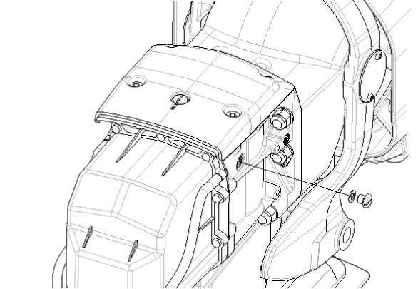
Figure 12 1 – Bracket 2 – Oil Reservoir Cap 3 – Oil Reservoir 4 – Retaining Strap
2. Empty the contents into a container large enough to hold the drained gear oil. 3. Install the oil reservoir (Figure 12, (3)) in the bracket. 4. Place the stern-drive in full trim limit
OUT position. 5. Remove the oil fill / drain plug and gasket (Figure 13).
(2) (1)
0006031
Figure 14 1 – Oil Vent Plug 2 – Gasket
NOTICE: If any water drains from the oil fill / drain hole, or if it appears milky, the stern-drive may be leaking and should be checked immediately by your authorized Yanmar Marine dealer or distributor.
8. Remove the case plate cover, filter cover, magnet and filter. Clean or replace the filter and magnet.
(4) (5) (6)
Model Capacity Fluid Type
ZT350 2500 mL (85 oz) GL-5 Hypoid Gear Oil
(1)
(1) (2) (3)
0006441
Figure 15 1 – Oil Level Sight Glass 2 – Filter Opening 3 – Filter 4 – Magnet 5 – Filter Cover 6 – Case Plate Cover
9. Lower the stern-drive so that the propeller shaft is level. Fill the sterndrive through the oil fill / drain hole with the specified oil until an air-free stream of oil flows from the filter opening. Install the filter, magnet, filter cover and case plate cover. 10. Continue to fill the stern-drive with oil through the oil fill / drain hole until an airfree stream of oil flows from the oil vent hole. 11. Install the oil vent plug and gasket.
Torque the oil vent plug.
Oil Vent Plug Torque N·m lb-ft
15 11 12. Continue to pump gear oil into the oil reservoir circuit until the gear oil appears in the oil reservoir. 13. Fill the oil reservoir so that the oil level is within the operating range.
NOTICE: NEVER overfill.
(2)
0006337
Figure 16 1 – Oil Reservoir Cap 2 – OPERATING RANGE Line
14. Ensure that the rubber gasket is inside the cap and install the cap. NEVER over-tighten. 15. Remove the pump from the oil fill / drain hole. Quickly install the gasket and oil fill / drain plug. Torque the oil fill / drain plug.
Oil Fill / Drain Plug Torque N·m lb-ft
15 11 16. Check the oil level in the oil reservoir after first use.