12 minute read
Page REF


The maintenance intervals in this manual If you wish to keep your vehicle in peak performance and resale value of your vehicle. are provided with the assumption that you, condition at all times, you may wish to When the vehicle is new, it should be not the dealer, will be carrying out the work. perform some of these procedures more serviced by a factory-authorised dealer These are the minimum maintenance intervals often. We encourage frequent maintenance, service department, in order to preserve the recommended by us for vehicles driven daily. because it enhances the efficiency, factory warranty.
Underbonnet view of a 1.3 litre model
1 Battery 2 Brake fluid reservoir 3 Brake servo 4 Throttle body 5 Fuel injectors 6 Spark plugs 7 Oil filler cap 8 Air cleaner/air flow meter assembly 9 Timing belt cover 10 Ignition distributor 11 Coo/ant expansion tank 12 Front suspension strut top mounting 13 Ignition coil 14 Exhaust CO sampling pipe
Front underbody view
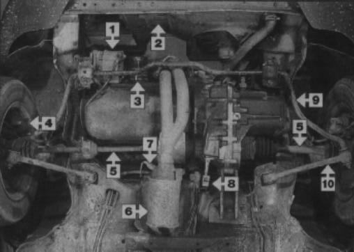
1 Alternator 2 Radiator 3 Oil filter 4 Front brake caliper 5 Driveshaft 6 Catalytic converter 7 Lambda sensor 8 Gearchange linkage 9 Anti-roll bar 11 Lower suspension arm
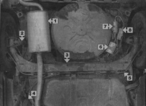
1 2 3 4
5 6 7 8 Exhaust tailbox Rear shock absorber Rear axle beam Rear brake pressurre regulating valve Handbrake cable Fuel filter Line fuel pump Accumulator we
Maintenance procedures
General information
This Chapter is designed to help the home mechanic maintain his/her vehicle for safety, economy, long life and peak performance.
The Chapter c o n t a i n s a master maintenance schedule, followed by Sections dealing specifically with each task in the schedule. Visual checks, adjustments, component renewal and other helpful items are included. Refer to the accompanying illustrations of the engine compartment and the underside of the vehicle for the locations of the various components.
Servicing your vehicle in accordance with the mileage/time maintenance schedule and the following Sections will provide a planned maintenance programme, which should result in a long and reliable service life. This is a comprehensive plan, so maintaining some items but not others at the specified service intervals, will not produce the same results.
As you service your vehicle, you will discover that many of the procedures can and should - be grouped together, because of the particular procedure being performed, or because of the proximity of two otherwiseunrelated components to one another. For example, if the vehicle is raised for any reason, the exhaust can be inspected at the same time as the suspension and steering components.
The first step in this maintenance programme is to prepare yourself before the actual work begins. Read through all the Sections relevant to the work to be carried out, then make a list and gather all the parts and tools required. If a problem is encountered, seek advice from a parts specialist, or a dealer service department.
Intensive maintenance
If, from the time the vehicle is new, the routine maintenance schedule is followed closely, and frequent checks are made of fluid levels and high-wear items, as suggested throughout this manual, the engine will be kept in relatively good running condition, and the need for additional work will be minimised.
It is possible that there will be times when the engine is running poorly due to the lack of regular maintenance. This is even more likely if a used vehicle, which has not received regular and frequent maintenance checks, is purchased. In such cases, additional work may need to be carried out, outside of the regular maintenance intervals.
If engine wear is suspected, a compression test (refer to the relevant Part of Chapter 2) will provide valuable information regarding the overall performance of the main internal components. Such a test can be used as a basis to decide on the extent of the work to be carried out. If, for example, a compression test indicates serious internal engine wear, conventional maintenance as described in this Chapter will not greatly improve the performance of the engine, and may prove a waste of time and money, unless extensive overhaul work is carried out first.
The following series of operations are those which are most often required to improve the performance of a generally poor-running engine:
Primary operations
a) Clean, inspect and test the battery (refer to “Weekly checks”). b) Check all the engine-related fluids (refer to “Weekly checks”). cl Check the condition and tension of the auxiliary drivebelt (Section 15). d) Renew the spark plugs (Section 7.6). e) inspect the distributor cap and rotor arm (refer to the relevant Section of
Chapter 5B). f) Check the condition of the air filter, and renew if necessary (Section 1 7). g) Renew the fuel filter (Section 21). h) Check the condition of all hoses, and check for fluid leaks (Section 5). i) Check the exhaust gas emissions (refer to
Section 14).
If the above operations do not prove fully effective, carry out the following secondary operations: All items listed under “Primary operations”, plus the following: a) Check the charging system (refer to the relevant Section of Chapter 5A). b) Check the ignition system (refer to the relevant Section of Chapter 5B). c) Check the fuel system (see relevant
Section of Chapter 4A or B as applicable). d) Renew the distributor cap and rotor am, (refer to the relevant Section of Chapter 5B). e) Renew the ignition HT leads (refer to the relevant Section of Chapter 50).
10 000 mile/12 month service
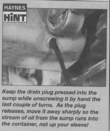
1 Frequent oil and filter changes are the most important preventative maintenance procedures which can be undertaken by the DIY owner. As engine oil ages, it becomes diluted and contaminated, which leads to premature engine wear. 2 Before starting this procedure, gather all the necessary tools and materials. Also make sure that you have plenty of clean rags and newspapers handy, to mop up any accidental spills. 3 The oil draining procedure should ideally be carried out when the engine is warm, as warm oil runs more freely than cold oil. In addition, more built-up engine ‘sludge’ will be removed with the oil, as it is drained . Take care, however, not to touch the exhaust or any other hot parts of the engine when working under the vehicle. To avoid any possibility of scalding, and to protect yourself from possible skin irritants and other harmful contaminants in used engine oils, it is advisable to wear gloves when carrying out this work. 4 Access to the underside of the vehicle will be greatly improved if it can be raised on a lift, driven onto ramps, or jacked up and supported on axle stands (see “Jacking and vehicle support”). Whichever method is chosen, make sure that the vehicle remains level, or (if it has been jacked-up at an angle), that the drain plug is at the lowest point. 5 Using a socket and wrench or a ring spanner, slacken the sump drain plug about half a turn until it can be rotated by hand (see illustration). Position the draining container under the drain plug, (noting that the stream of oil may initially run out at an angle, rather than straight down) then unscrew the plug completely (see Haynes Hint). Recover the sealing ring from the drain plug. 6 Allow some time for the old oil to drain, noting that it may be necessary to reposition the container as the oil flow slows to a trickle. If you are working outside, shield the container from draughts that may splash the stream of oil onto the ground. 7 After all the oil has drained, wipe off the drain plug with a clean rag, and fit a new sealing washer. Clean the area around the drain plug opening, and refit the plug. Tighten the plug securely. 8 If the filter is also to be renewed, move the container into position under the oil filter, which is located on the front side of the cylinder block, below the inlet manifold. 9 Using an oil filter removal tool if necessary, slacken the filter initially (by turning it in an anticlockwise direction), then unscrew it by hand the rest of the way (see illustration). Note that the filter will still contain some oil be prepared for an amount of leakage as the filter is unscrewed. Hold it with the sealing face uppermost until it can be emptied into the draining container. 10 Use a clean rag to remove all oil, dirt and sludge from the filter sealing area on the engine. Check the old filter to make sure that the rubber sealing ring has not stuck to the engine. If it has, carefully remove it. 11 Apply a light coating of clean engine oil to the sealing ring on the new filter, then screw it into position on the engine. Tighten the filter firmly by hand only - do not use any tools, as these may damage the outer surface filter. 12 Remove the old oil and all tools from under the car then lower the car to the ground (if applicable). 13 Remove the dipstick, then unscrew the oil filler cap from the cylinder head cover or oil filler/breather neck (as applicable). Fill the engine, using the correct grade and type of oil (refer to “Lubricants fluids and capacities”). An oil can spout or funnel may help to reduce spillage. Pour in half the specified quantity of oil first, then wait a few minutes for the oil to .


collect in the sump. Continue adding oil a small quantity at a time until the level is just above the lower mark on the dipstick. Adding approximately 1.0 litres will raise the level from the lower mark to the upper mark on the dipstick. Refit the filler cap. 14 Start the engine and run it for a few minutes; check for leaks around the oil filter seal and the sump drain plug. Note that there may be a delay of a few seconds before the oil pressure warning light goes out when the engine is first started, as the oil circulates through the engine oil galleries and (where applicable) the new oil filter before the pressure builds up. If the oil pressure warning light does not extinguish after the engine has started and run for several seconds, stop the engine immediately and check for leaks around the components that have been disturbed. 15 Switch off the engine, and wait a few minutes for the new oil to settle into the sump. With the new oil circulated and the filter now completely full, recheck the level on the dipstick, and add more oil as necessary. 16 Dispose of the used engine oil safely, with reference to “General repair procedures” in the Reference Sections of this manual.
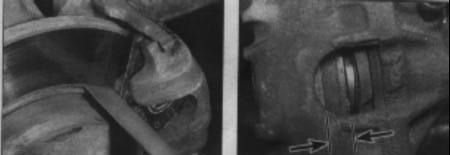
2.2a Checking the front brake outer pad linings for wear with a steel rule 2.2b Check the front brake inner pad linings through the hole in the caliper
2 Front brake pad check
1 Firmly apply the handbrake, then jack up the front of the car and support it securely on axle stands (see “Jacking and vehicle support”). Remove the front roadwheels. 2 Using a steel rule, measure the combined thickness of the lining and backing of the brake pads on both front brakes. This must not be less than 7.0 mm. Check the inner pad through the hole on the front of the caliper
(see illustrations).
3 For a comprehensive check, the brake pads should be removed and cleaned. The operation of the caliper can then also be checked, and the condition of the brake disc itself can be fully examined on both sides. Refer to Chapter 9 for further information. 4 If any pad’s friction material is worn to the specified thickness or less, all four pads must. be renewed as a set. Refer to Chapter 9. 5 On completion refit the roadwheels and lower the car to the ground.
Every 12 months - regardless of mileage

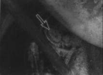
1 Jack up the rear of the car and support on axle stands (see “Jacking and v e h i c l e support”). Do not remove the wheels. 2 Working beneath the car remove the rubber plugs from the front of the backplates and check that the linings are not worn below the minimum thickness given in the Specifications (see illustration). If necessary use a torch. 3 If the friction material on any shoe is worn down to the specified minimum thickness or less, all four shoes must be renewed as a set. 4 At the same time check for signs of brake fluid leakage. 5 For a comprehensive check, the brake drum should be removed and cleaned. This will allow the wheel cylinders to be checked, and the condition of the brake drum itself to be fully examined (see Chapter 9). 6 Refit the rubber plugs then lower the car to the ground.

Note: This procedure does not apply to vehicles fitted with an automatic clutch cab/e adjustment mechanism.
Measurement
1 Park the vehicle and switch off the engine. Select neutral, then depress the clutch pedal several times, to settle the release mechanism components. With no pressure applied to the pedal, measure the distance between the pedal rubber and a fixed reference point, such as the bottom edge of the steering wheel - a length of batten can be used to serve as a measuring rule. 2 Gradually apply pressure to the clutch pedal, until firm resistance is felt, indicating that the release mechanism is beginning to disengage the clutch. At this point, repeat the measurement described in paragraph 1. 3 Compare the measurement with the value listed in the Specifications - if the free play exceeds the maximum permitted, adjust the cable as described in the following sub- : Section.
Adjustment
4 Open the bonnet and locate the clutch cable adjusting nut, on the upper surface of the transmission casing. 5 Rotate the nut through half a turn, using a spanner, to take up the slack in the cable. Measure the clutch pedal freeplay again, as described in the previous sub-Section. 6 Repeat the operations described in paragraphs 4 and 5 until the correct pedal freeplay is achieved.
5
1 Visually inspect the engine joint faces, gaskets and seals for any signs of water or oil leaks. Pay particular attention to the areas around the camshaft cover, cylinder head, oil filter and sump joint faces. Bear in mind that, over a period of time, some very slight seepage from these areas is to be expected -