30 minute read
Service side


1Oil filler cap
2Coolant inlet pipe
3Coolant pump
4Alternator
5Crankshaft pulley
6Fuel pump
7Fuel filter
8Lubricating oil filter
9Oil sump
10Oil dipstick
11Lubricating oil cooler
12Power socket for hydraulic pump, air compressor etc.
13Cylinder head
14Stop solenoid
Lubrication system
1Oil pressure sender
2Valve tappet with rocker arm lubrication
3Oil suction pipe
4Rocker arm
5Return to oil sump
6Spray nozzle for piston cooling
7Oil channel to piston cooling nozzle
8Lubricating oil cooler
9Lubricating oil pump
10Safety valve (pressure regulating valve)
11Reduction valve
12Lubricating oil filter
13Push rod, oil feed to rocker arm lubrication
14Oil sump
15Connecting rod bearing
16Crankshaft main bearing
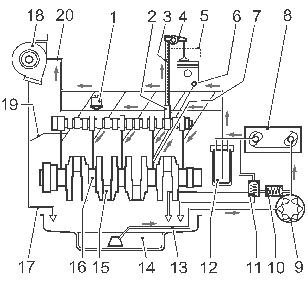
17Return flow from turbocharger to crankcase
18Turbocharger
19Return flow to oil sump
20Oil line to turbocharger
1)NOTE! Minimum distance 300 mm.
2)NOTE! Does not work laying down. Must be turned right (TOP).
Commencement of delivery, Fb
The engine is equipped with a separate injection pump for each cylinder. This means that the commencement of delivery, Fb, when necessary, has to be adjusted separate for each pump unit. The commencement of delivery, Fb, is adjusted with a shim, placed between lifter and injection pump.
To exchange only the injection pump, the formula Ts=(L0+A/100) is used, according to “Calculation 1” in “Technical data”
If engine block, camshaft or roller tappet are exchanged, the corrected fitting size, Ek, and new EPcode must also be calculated, according to “Calculation 2 and 3” in “Technical data”.
New EP-code must also be is indicated on the identification plate, in order for calculations during future replacement of injection pump to be correct.
Delivery pipes
IMPORTANT! The delivery pipes must be disposed of after disassembling.
The delivery pipes are deformed when tightened and all delivery pipes must be tightened with the same tightening torque.
If they are tightened with different tightening torque, the cylinders may take different load.
Reuse of delivery pipes may mean that the engine power is not complete.
If the delivery pipes for some reason have been damaged, for example during transport, they may not be bent right, but must be replaced.
Cooling system
1Coolant connection (inlet)
2Thermostat housing
3Coolant pump
4Lubricating oil cooler
5Cylinder cooling
6Cylinder head cooling
7Coolant connection (outlet)
Technical data
Low idle rpm
Highest full load speed rpm
Coolant
Volvo Penta glycol (antifreeze) mixed 45/55 with clean water
Anti-corrosion agent
Used only in markets where there is no risk of freezing, mixed with water3)
3) The anti-corrosion agent must not be mixed with glycol or other types of anti-corrosion fluid as this could result in negative consequences.
Water quality specification:
To avoid the risk of clogging in the cooling system, the coolant should be mixed with pure water to ASTM D4985. If any doubt about the purity of the water, distilled water or ready-mixed coolant should always be used instead
Lubrication
Engine
Lubrication ............................................................Forced circulation lubrication
Oil SAE................................................................. 15W 40
Oil temperature in sump........................................Normal 80°C (176°F) Max. 125°C (257°F)
Oil pressure at rated speed:
TAD530-532 450-480 kPa
TAD730-733 480-520 kPa
TD520GE/TAD520GE (1500 rpm) .........................280 kPa (40 psi)
TD520/GE/TAD720GE (1800 rpm) ........................330 kPa (48 psi)
TD520VE ..............................................................440 kPa (64 psi)
TAD520VE ............................................................390 kPa (56 psi)
TD720GE/TAD720/721/722GE ..............................400 kPa (58 psi)
TD720VE ..............................................................450 kPa (65 psi)
TAD720VE/TAD721VE.........................................350 kPa (51 psi)
Shut down switch setting:
520/720/721/722 GE, 732, 733 ..............................200 kPa (29 psi)
520/720/721/722 VE, 530, 531, 730, 731, 532.......50 kPa (7 psi)
Oil volume including filter:
TD520GE/TAD520GE ...........................................10 litre (2.64 US gallon)
TD520VE/TAD520VE ............................................13 litre (3.43 US gallon)
TD/TAD720, TAD721/722VE, TAD730/731GE ......20 litre (5.28 US gallon)
TAD721/722GE, TAD732/733GE ..........................34 litre (8.98 US gallon)
Tightening sequence for cylinder head screws
Manifold sideTD/TAD 520
TAD530-532
Tightening torque
Manifold
TAD730-733
Screws to cylinder head are reusable only five times.
Step 1:................................................................ 50(37 lbf.ft)
Step 2:................................................................ 130(96 lbf.ft)
Step 3:................................................................ 90° angle tightening
Tightening torque
These tightening torques apply to oiled bolts and nuts. Parts that have been degreased (washed) should be oiled before they are fitted.
Special tightening torque’sNm / angle tightening (lbf.ft)
Group 21 Engine
Main bearing caps
Screws to main bearing caps are reusable only three times.
Step 1................................................................. 50 (37 lbf.ft)
Step 2................................................................. tighten angularly 60°
Step 3................................................................. tighten angularly 60°
Connecting rod big-end bearing
Use new screws every time.
Step 1................................................................. 50 (22 lbf.ft)
Step 2................................................................. tighten angularly 60°
Step 3................................................................. tighten angularly 60°
Flywheel
A) Flywheel with screws of max 30 mm length
Step 1:................................................................ 20 – 30 (15 – 22 lbf.ft)
Step 2:................................................................ tighten angularly 60°
Step 3:................................................................ tighten angularly 30°
B) Flywheel with screws up to 45 mm length
Step 1:................................................................ 20 – 30
Step 2:................................................................ tighten angularly 60°
Step 3:................................................................ tighten angularly 60°
C) Flywheel with a screw length between 50 – 85 mm
15 – 22 lbf.ft)
Step 1:................................................................ 30 – 40 (22 – 30 lbf.ft)
Step 2:................................................................ tighten angularly 60°
Step 3:................................................................ tighten angularly 60° Flywheel
Cylinder head
See previous page.
V-belt pulley
Screws are reusable only three times. tighten angularly 60° tighten angularly 60°
Group 23 Fuel system
NOTE! Use a new delivery pipe after every disassembly
NOTE! Make sure that you use the same tightening torque for all delivery
Determination of shim thickness when changing the injection pump.
Mathematical formula for new shim thickness: T s = Ek - (L0 + A/100)
Actual shim thickness, Ss, can be found in Table 2. Ss → → → → T s
NOTE! This formula is applicable when changing the injection pump ONLY.
Example: Change of injection pump for cylinder 3 on a TAD 720 engine.
1.Read the EP code for cylinder 3 from the engine identification plate, in the “EP” column, e.g. 397. (Sequence from top: row 1 = cyl. 1, row 2 = cyl. 2 etc.).
2.Using the EP code, read the corrected fitting size (Ek) for the injection pump from Table 3. Ex. EP code = 397 → → Ek = 146.9 mm.
3.Take the manufacturing tolerance for the injector pump length, A, from the new injector pump, Ex. 63 (see figure)
NOTE! If the value is not visible, remove possible dirt, without scraping.
The tolerance value A is divided by 100 in calculations.
4.Take the standard size for the injector pump, L0 , from Table 1. Ex. 143 mm.
5.Determine the theoretical shim thickness, T s , according to the formula: T s = Ek – (L0 + A/100) (Also see examples in “Calculation 1”) Ex.T s = 146.9 mm – (143 mm + 0.64 mm) T s = 4.54
6.Select shim thickness, S s , from Table 2. Ex. T s = 4.54 mm → → → → → S s = 4.5 mm
Determination of shim thickness when the injection valve opens
Performed when replacing engine block, camshaft, or roller tappet.
Mathematical formula for the new shim thickness:
T s = L-[(Fbakt - Fbnom)x Vhkorr + Vh nom + L o + A/100)]
The actual shim thickness can be found in Table 2. S s → T s
NOTE! After determining the shim thickness, a new EP code MUST ALWAYS be determined, according to “Calculation 3”, in order for changing of pump to be correct at a later point in time.
2.6
Factorunit Explanation
Fbakt ºC/AInjection angle, measured on protractor according to method.
Fb nom ºC/AInjection angle, see table 1.
Vhkorr mm/ºC/APre-stroke, correction factor see table 1.
Vh nom mmPre-stroke, nominal, see table 1.
LmmMeasured length between block and roller tappet.
L0 mmBasic measurement of injection pump.
A/100mm Manufacturing tolerance, written on injection pump.
T s mmTheoretical shim thickness.
S s mmShim thickness.
S (1, 2, 3)xxxTotal of calculation.
EPxxxCode value, see table 3 or engine identification plate.
E k mmTotal of calculation. Only applicable when determining EP code.
Determination of the corrected fitting size, Ek, and EP code for an injection pump.
NOTE! When you change the engine block camshaft or roller tappet, you must determine the corrected fitting measurement, Ek, and change the relevant EP code on the engine identification plate.
Mathematical formula for the corrected fitting size, Ek:
Ek = L - [(Fbakt - Fbnom) x Vhkorr + Vhnom)]
New EP code is found in Table 3.2 Ek → EP code
Checks and adjustments
Compression test (21002)
Special tools: Adapter for compression testing
999 8694
Compression gauge
998 8539
The injectors have been removed, the valve clearance has been checked.
1.Fit adapter 999 8694.
2.Use the existing injector yoke. Tighten the screw to........................... 19 ±2 Nm (14 ±1.5 lbf ft).
3.Connect the compression tester, 998 8539. Turn the engine over with the starter motor. Compression: 3-3.8 MPa (435-551 psi).
NOTE! Make sure that the fuel control rod is in the no fuel position (stop position).
The measured compression depends on the engine speed during the measuring process and the ambient air pressure.
It is difficult to give an exact limit value due to the ambient air pressure. We recommend that the compression test is to compare the cylinders of the engine. If the pressure difference is greater than 15% the cylinder in question should be dismantled to determine the cause.
NOTE! Refit the injector with a new copper gasket and tighten to 19 ±2 Nm (14 ±1.5 lbf ft).
Fit the new fuel delivery pipe and tighten in two stages 5 Nm and 25 0 Nm (19 0 lbf ft).
IMPORTANT! All delivery pipes must be tightened with the same tightening torque.
Tighten the rocker cover to 11 ±1 Nm (6.6 ±0.7 lbf ft).
NOTE! The fuel leakage lines must always be replaced if removed.
Injectors, checking/adjusting (23712, 23713)
NOTE! You must observe the utmost cleanliness when working on the injection system. Use only clean test oil that meets ISO 4113 or clean diesel to test the injector.
NOTE! Let an authorized workshop do the tests and adjustments. The test requires equipment not sold by AB Volvo Penta.
WARNING! Be very careful when working with the fuel injector nozzle. The fuel pressure jet can penetrate deep into the skin tissue and cause blood poisoning.
1.Connect the injector to the nozzle tester.
2.Check the opening pressure. For control value for the opening pressure, see “Technical data”.
NOTE! The opening pressure is different depending on if the injector or spring is new or used.
3.Check the density after the injector has opened. The pressure may, at the most, drop to 5 MPa (725 psi) /5 sec.
By keeping the pressure constant, 2 MPa (290 psi) below opening pressure for 10 seconds, make sure that no drips occur.
Set the opening pressure for the injector
4.Take off the cap nut and remove all parts.
5.Wash the details in an ultrasonic cleaner, alternatively washing petrol or Vanolen.
6.Inspect the injector details, using an injector microscope.
7.Dip the parts in oil before assembly.
The order for removing parts is:
1Cap nut
2Injection nozzle
3Adapter
4Pressure pin
5Compression spring
6Shim
8.Set the pressure by selecting an appropriate shim. (A thicker shim increases the opening pressure.) Tighten the cap nut to 40 ±5 Nm (33 ±3.7 lbf ft). Recheck the injector in the nozzle tester.
9.Check the seal
Dry the nozzle and nozzle holder with compressed air. Press down the tester handle until you obtain a pressure of around 2.0 MPa below the previously measured opening pressure. Example: Pressure gauge: reading: set to:
For opening pressure, see Technical Data (1MPa = 145 psi).
10.If no leaks appear within 10 seconds the nozzle is sealed.
11.If the nozzle is leaking, dismantle and clean the injector to prevent it from leaking. If the nozzle still is leaking, replace the injector. Reuse is not permitted.
12.Chatter characteristic and spray pattern tests.
NOTE! Shut off the tester pressure gauge, for this test.
The chatter test provides an audible check of how easily the nozzle needle is moving in the nozzle body. New injectors give a different sound compared with used injectors. It worsens due to wear in the needle seat area. If an injector nozzle does not make the chatter noise despite having been cleaned, it must be replaced.
A used injector chatters clearly when the handle is moved quickly, and shows a well-distributed spray pattern. The condition of the nozzle is difficult to establish concerning spray pattern.
Incorrect spray pattern may cause engine damage.
Disassembly, complete engine
The repair methods that are shown in this chapter apply to the standard specification only, i.e. components in specially smanufactured engines are not shown.
Exposure of engine
1.Mark up and loosen all cabling and terminal boxes. Loosen the exhaust bend.
2.Drain and collect the remaining oil and coolant, and dispose of them in accordance with applicable environmental regulations.
3.Remove the air filter and crankcase ventilation hose.
4.Remove the hose between the turbocharger and the air filter.
5.Remove tha alternator as well as extra power sources, alternator belt and bracket, see “Drive belts, adjusting and replacing”.
Fitting of fixture
Turbo charger, remove
1.Remove the oil pressure pipe, oil return pipe, and charger air pipe.
2.Remove the mounting nuts and the turbo charger.
3.Plug (1) the turbo and the connections for the oil return and the oil pressure pipes in the engine block.
4.Attach the engine bracket 999 8671 (1) to the engine and tighten to 25 Nm (18.5 lbf ft).
NOTE! Use the accompanying screws, since their strength is higher than that of standard screws.
5.Tighten the engine firmly in the engine repair stand 999 6845.
Engine, disassembly
1.Remove the oil-trap housing for the crankcase ventilation (see picture).
2.Catch any remaining oil and dispose of it in accordance with the environmental regulations.
3.Loosen the fuel hose between filter and fuel pump. Remove the fuel pump, belt and bracket. Remove the fuel line between filter and fuel duct.
NOTE! Plug the fuel system so that dirt can not enter.
4.Remove the coolant outlet pipe (1) if required (see picture).
5. The starter motor can be removed at this stage, but it is easier to leave it on and remove it together with the transmission cover.
6. Remove the engine speed governor. Use a Torx socket E 10 (for electronic governors, use Allen key 6).
7. Drain the fuel from the fuel duct in the engine by removing the hollow screw at the front of the engine block and the overflow valve and fuel return vent. Remove the screw at the rear of the engine block. Remove the fuel and oil filters using tool 999 9179.
8. Remove the cooler housing.
9.Remove the coolant pump and coolant housing, according to one of the pictures, depending on coolant pump model.
The lower model is removed with 7 screws. First remove the bearing bracket for the intermediate pulley.
10.Loosen the screws and remove the rocker cover and the gasket.
NOTE! Make sure that dirt trapped between the inlet manifold and the rocker cover does not fall down into the engine. Clean thoroughly before removing the rocker cover.
11.Remove the fuel return lines together with the overflow valve and air vent screw.
12.Remove the delivery pipes, complete with the rubber seals.
NOTE! Cover the injector and injector pump openings.
13.Remove the stop solenoid (alternatively the plug if the governor is electronic).
NOTE! Be careful not to damage the control rod. Install 999 8682 to keep the control rod in the protected "stop" position.
14.Remove the injectors. Use a Torx socket E 10. Use puller 999 6400 together with socket 999 8007 if any injector is stuck in the cylinder head.
NOTE! To prevent dirt and water coming in the injector hole, make sure to clean well around the injector before removing it.
16.Remove and mark up the push rods.
17.Remove the inlet manifold and gasket.
18. Remove the exhaust manifold (1).
19.Loosen the screws to the cylinder head, using the torx socket E18.
Connect lifting wires to the lifting eye bolts and remove the cylinder head.
NOTE! Weight is approx. 80 kg (720-722).
NOTE! Make sure that the injection pump tappet is on the base circle when removing the pumps
NOTE! Mark up all parts when removing to make sure the components match and will be fitted to the correct position.
20.Remove the injection pumps. Start with the screw closest to the flywheel. Put them in a stand to protect them from dirt.
NOTE! Be careful with the loose shim.
21.Using pliers or a pen magnet, lift out and mark the roller tappets together with the shim.
NOTE! Attach the shim firmly to its respective injection pump.
22.Pull out the dipstick.
23.Remove the oil sump.
NOTE! The oil sump is mounted with a fluid gasket and may be stuck. Use a bending bar in the referring grooves.
24.Remove the oil suction pipe.
25.Remove the crankshaft pulley and damper (if installed). Use a Torx socket E20.
26.Remove the oil pump/front cover.
27.Remove the cover plate on the flywheel housing.
28.Remove the flywheel housing. Use Torx sockets E20 and E14.
29.Turn the engine through 90°. Remove the plastic plugs between every second screw, which are a locking device for the flywheel screws.
Loosen the screws on the flywheel, but let them stay in place.
Use 999 8681 to block the flywheel.
30.Connect lifting eye bolts M10 (1) and lifting wire. Remove the flywheel.
WARNING! Be careful when removing the flywheel as it is very heavy.
31.Remove the transmission housing if this has not been removed before.
32.Turn the engine through 90°. Mark up the the bearing caps of the connecting rods and loosen the screws. Remove the bearing caps and the bearing halves. Take care of the bearing halves.
33.Remove the pistons, complete with connecting rods.
Measure the liners before the main bearings are loosened.
34.Turn the engine through 90°. Set the dial gauge to.................. 108 mm (4.25”)
35.Make sure that the liners are not damaged or cracked.
Measure the inside diameter of the cylinderliners. Measure at three different levels, according to the picture, both in the longitudinal and in the transverse axis.
Diameter: 108 +0.02 mm (4.252 +0.001")
Wear limit: 108.1 mm (4.256”)
36.Turn the engine so that the crankshaft is directed upwards.
Make sure that the camshaft and crankshaft gears are marked.
37.Make sure that the crankshaft bearing caps are marked. Remove the securing screws and remove the bearing caps and the main bearing halves.
38.Remove the thrust washers (1) at main bearing cap 2 (the thrust bearing pivot). Bearing cap 1 nearest the flywheel end.
39.Lift the crankshaft out of the engine block. NOTE! The crankshaft is heavy (approx. 75 kg, 720722, 730-733). Use a soft strap to lift it out.
40.Remove the thrust washers and bearing shells at main bearing cap 2
NOTE! Mark up the bearing halves if they are to be used again.
41.Press the piston cooling nozzles out.
42.Remove the idler gear.
NOTE! Does not apply to electronic governor.
43.Pull out the camshaft.
NOTE! Be careful when removing the camshaft to prevent damaging the bearings.
44.Remove the valve tappets and mark them if they are to be used again.
45.Remove the securing screw. Pull out the control rod.
46.Remove the cylinder liners. Use extractor plate 999 8675 together with liner extractor 999 6645 and supports 999 6395 and 999 6394.
NOTE! Mark up the liners if they are to be used again.
WARNING! When fluorocarbon rubber is subjected to high temperatures highly corrosive hydrofluoric acid can be produced. Skin contact can cause severe burning. Be very careful and see “Safetyinstructions for fluorocarbon rubber”.
Assembly, complete engine
NOTE! Tighten the screw plugs as stated.
Use new copper seals for items 4 and 13. Insert item 24 with locking compound (part no1 161 053-2).
Item 4= 35 ±3.5 Nm (26 ±2.6 lbf ft)
Item 6= 95 ±9.5 Nm (70 ±7.0 lbf ft)
Item 7= 65 ±6.5 Nm (48 ±4.8 lbf ft)
Item 8= 35 ±3.5 Nm (26 ±2.6 lbf ft)
Item13=35 ±3.5 Nm (26 ±2.6 lbf ft)
Item24=10 ±2.0 Nm(7.4 ±1.5 lbf ft)
Engine, assembly
Cylinder liner, installing
1.Ensure that the cylinder liner area and linersealing surfaces are completely clean.
2.Oil the engine block and cylinder liner in the areas marked X in the diagram. Fit new O-rings.
NOTE! Make sure the cylinder liner is correct mounted in the engine block, compare the liners height compare to the engine block, see "Technical data".
NOTE! Before insertion, IMPORTANT! Fit it without sealer, well cleaned and dry.
3.Fit the cylinder liner in to the correct position in the engine block. Drive it in as far as possible.
Piston cooling nozzles
4.Check that the oilways are not blocked. Fit the piston cooling nozzles in the correct position in the engine block. Press the piston cooling nozzles in as far as they will go.
Cams/camshaft
5.Insert the valve tappets (lightly oiled).
6.Fit the camshaft.
NOTE! Be careful when fitting the camshaft to prevent damaging the bearings.
7.Fit the main bearing shells into the engine block.
8.Mark the crankshaft if necessary (to make fitting easier).
9.Mark the camshaft, if necessary, and put it in place.
10.Insert the crankshaft. The marks must line up. Use a ruler and make sure that the marks line up through the centre of the crankshaft and camshaft.
11.Insert the half thrust bearing without lug. NOTE! The thrust bearing running face must be towards the crankshaft.
12.Fasten the half thrust bearing with lug to the thrust bearing caps (using a little grease).
NOTE! The thrust bearing running face must be towards the crankshaft.
13.Fit the bearing shells into the main bearing caps and lightly oil them.
14.Oil the main bearing caps and put them in place. NOTE! The main bearing caps are numbered 1-5 or 17 depending on engine type. Bearing cap 1 nearest the flywheel end.
NOTE! Make sure that the thrust washers on the bearing caps fit the washers in the block.
15.Tighten the main bearing cap screws as follows:
Initial torque: 50 Nm (37 lbf ft)
1st tightening angle: 60°
2nd tightening angle: 60°
NOTE! You can use the bolts three times, if you know how many times they have been used. (Make a punch mark for each of the following usages.)
Govenor idler gear (mechanical governor)
NOTE! Electronic governors do not have an idler gear.
16.Fit the govenor idler, complete with bearing journal.
17.Using locking compound, insert the screw and tighten it, using thread sealer (1161053-2) to............................................................. 21 Nm (15 lbf ft).
Control rod
18.Fit the control rod, complete with guide sleeve.
19.Put thread sealer (1161053-2) on the screw and tighten to 10 +2 Nm (7.4 +1.5lbf ft). 00
Transmission housing
NOTE! The transmission cover and starter motor can be installed together.
20.Apply silicon sealing compound (1161231-4) as shown in the diagram to the sealing surface for the transmission housing. Lightly oil the crankshaft seal.
21.Fit the transmission cover, without tightening the screws.
NOTE! Line it up with the oil sump sealing surface.
22.Tighten the screws to......................... 21 ±2 Nm (15 ±1.5 lbf ft).
Oil pump/cover
23.Lightly oil the oil pump rotor.
24.Attach the gasket to the oil pump/cover with a little grease.
25.Fit the oil pump rotor onto the crankshaft. (It will only go in one position).
26.Fit the oil pump/cover without tightening the bolts. IMPORTANT! Push the cover upwards and align it with the oil sump sealing surface.
27.Tighten the oil pump/cover screws to................................ 21 ±2 Nm (15 ±1.5 lbf ft).
Piston complete with connecting rod
28.Fit the bearing shells into the connecting rod and cap. Lightly oil.
29.Position the piston ring gaps 120° apart.
30.Use piston ring compressor 999 8687 and push the piston (complete with connecting rod) into the engine block.
IMPORTANT! Be careful, the piston rings are frail and can easily be damaged. The piston ring compressor may not be opened after the piston has been placed in the tool, since the piston rings then can be damaged. Always push out the piston before the tool is opened.
NOTE! The flywheel symbol (punched into the top of the piston and the guide pins on the connecting rod) must point towards the flywheel.
31.Lightly oil the crank pin. Press the connecting rod onto the crank pin. Fit the big end bearing cap (in accordance with the marking).
32.Tighten the new big end bearing screws as follows:
Initial torque: 30 Nm (22 lbf ft)
1st tightening angle: ........................................ 60°
2nd tightening angle: 60°
NOTE! You should renew the big end screws every time you remove them.
33.Turn the crankshaft to check that the connecting rods are running freely on the connecting crank pins.
Oil suction pipe/oil sump
34.Fit the oil suction pipe with a new gasket.
35.Tighten the oil suction pipe to the oil pump housing. Tighten to............................. 21 ±2 Nm (15 ±1.5 lbf ft).
36. Cut off the protruding gasket.
NOTE! Do not pull away protruding dried silicone. Fill the joints in the oil sump sealing surface with silicone (part no. 1161231).
37.Position the new gasket on the engine block.
NOTE! The gasket consists of four parts.
38.Fill the indentations in the gasket with silicon (part no. 1161231).
Control rod, measuring
NOTE! Measure the control rod (fuel rack) travel without the injection pumps fitted.
40.Turn the engine through 180°. Attach the control rod (fuel rack) measuring fixture 999 8684 on the leading edge of the engine.
41.Measure from the measuring fixture to the control rod (fuel rack) stop position (see diagram). Use rule depth gauge 998 5471.
42.Measure from the measuring fixture to the control rod (fuel rack) start position. Use rule depth gauge 998 5471.
The difference between the start and stop positions is the control rod (fuel rack) travel.
Stated measurement = 17.0 mm - 17.5 mm (0.67" - 0.69")
Example:
Stop position = 30.7 mm (1.21")
Start position = 13.4 mm (0.53")
Control rod travel = 17.3 mm (0.68")
43.Turn the measuring fixture (see diagram). Push the control rod (fuel rack) to the stop position by hand, using the stop screw.
NOTE! Only tighten the stop screw gently by hand.
Determining the injection angle, shim thickness, and fitting of injection pumps
NOTE! The injection angle and type of camshaft is stated on the engine identification plate. To follow the procedure described below, is only required if the engine block, camshaft or a roller tappet has been replaced.
When fitting existing injection pumps see section “Injection pump installation” in this chapter. When changing an injection pump only, see chapter "Changing injection pump".
44.Fit the protractor (999 8679) to the flywheel flange on the crankshaft.
NOTE! Make sure that you tighten the screws so that there is no play.
45.Attach a pointer. Use a magnetic stand.
46.Position the measuring bar (999 8678) with spacers on the engine block over the piston belonging to the injection pump for which you are setting the timing. Turn the crankshaft in the direction of engine rotation until the dial gauge has reached its turning point. Set the dial gauge to “0”.
IMPORTANT! The dial gauge must be placed in the center of the gudgeon pin direction.
At top dead center the piston is still approx. 1°. To find the top dead center, the procedure below must be performed.
47.Turn the crankshaft through 350° in the engine rotation direction until 8 mm (0.32") before top dead centre (dial gauge turning point). Set the protractor to “0”.
48.Turn the crankshaft through 350° in the opposite engine rotation direction until 8 mm (0.32") before top dead center (dial gauge turning point). Read the value.
Example: 50°.
49.Turn the crankshaft until you reach half of the value you have determined on the protractor. Example: (0° + 50°)/2 = 25° ACTUAL value. This is the same as the top dead centre and should correspond with the top dead center on the dial gauge.
50.Set the protractor to “0”.
NOTE! Leave the protractor on for the next phase, in order to determine the injection angle.
Determining the injection angle
Measuring of permissible variation, engine block.
(We suggest that Tables 1, 2, and 3 as well as Calculations 2 and 3 from section”Technical data” in this book are photocopied.)
51.Install the dial gauge 998 9876 in the measuring fixture 999 8685 with a preload of 5 mm (0.2"). Zero the dial.
The set value (Le) is 150 mm (5.9") (see figure).
1 = Gauge 999 8685
2 = Depth gauge 999 8685
3 = Dial gauge 998 9876
52.Position the roller tappet, without shims, for the injector pump in question on the base circle of the camshaft. Insert the depth gauge carefully in the injection pump hole.
NOTE! Make sure that the guide on the roller tappet ends up in the groove in the material.
53.To do this, turn the crankshaft through 180° against the direction of rotation, until you are certain that the roller tappet is placed on the base circle.
54.Take measurement “L” and enter it in “Calculation 1” in "Technical data".
Depth gauge: 150 mm (5.9")
Dial gauge (X mm): 2.18 mm (0.086")
L = 150 + 2.18 = 152.18 mm
(12.75 + 0.086 = 12.83")
Measuring of permissible variation, roller tappet and camshaft.
55.Zero the dial gauge.
56.Read the injection angle, Fbnom, on the engine identification plate.
Read pre-stroke, Vhnom, in Table 1 in ”Technical data”.
Enter both values in calculations 2.1 and 3.1 in ”Technical data”.
Example:
Fb nom = injection angle = 6.0°
Camshaft= A
Vh nom = pre-stroke = 6.11
57.Turn the crankshaft in the direction of engine rotation until the dial gauge shows (-) Vhnom.
Example: 7-6,11 = 0,89
The dial gauge was zeroed at 7 mm pre-stroke and when it shows 0.89 in the example, you have reachedVh nom
58.You can now, on the protractor, read the value (eg. 354,5°) for when the injection valve should have opened.
Example: 360 - 354.5 = 5.5
Enter it into calculations 2.1 and 3.1 in "Technical data".
Example: FB akt = 5.5°
59.Read off demension “A” = the code for the injection pump length and enter it into “Calculation 2.1” in “Technical data”.
Example: A/100 = 0.63 mm (0.025")
60.Remove the depth gauge with the dial gauge. Complete the calculations for shim thickness in “Calculation 2.2” in “Technical data”.
NOTE! Don’t forget to change the EP-code on the engine identification plate.
61.Slide the shim in place along a scewdriver into the roller tappet.
NOTE! Perform the measurement procedure in steps 51-61 above for each injection pump.
Injection pump Installation
62.When refitting pumps: place the existing roller tappets with their belonging shims.
63. IMPORTANT! Turn the injection pump linkage lever to middle position.
64. Make sure the injection pumpcam, for the cylinder in question, is on the base circle. Turn the engine, using tool 999 8681 or protractor 999 8679.
NOTE! Make sure that the control rod is still in the stop position, held in place with the tools 999 8682 or 999 8684.
65.Lightly oil the O-rings, using lubricant 1141699, on the injection pump and carefully insert the pump.
IMPORTANT! Make sure that the injection pump linkage lever has entered the slot in the control rod before pushing it down.
1. Fuelrack
2. Shim for pump element
3. Roller tappet for pump element
66.Put the pump flange in place with the camfered hole side facing the pump. Oil the screws lightly and tighten the screws evenly to..................................5 Nm (3.7 lbf ft). Back she screws off..................................... 60°.
67.Turn the injection pump carefully counterclockwise. Use a torque wrench with gauge and 11668403. Stop turning when the pump has reached its stop position and the torque is increased by 1Nm (0.74 lbf ft).
Observe the torque required on the torque wrench gauge to turn the injection pump, e. g. 3.5 Nm (2.6 lbf ft).
Example: 3.5 + 1 = 4.5 Nm
68.Tighten the screws 60° clockwise then alternately with a torque of 7, 10 and 30 Nm (5.2, 7.4 and 22.2 lbf ft) .
NOTE! Start with the screw furthest away from the flywheel.
NOTE! Check that the control rod (fuel rack) is moving freely after each injection pump has been installed.
Repeat the steps above for each pump.
69.Remove the indicator 999 8679, if it has been fitted.
Let tool 999 8684 stay in place.
Measure the control rod (fuel rack) travel with the injection pumps installed
70.Loosen the measuring fixture screw and turn it from the control rod and tighten the measuring fixture screw at the measuring position.
71.Measure from the measuring fixture to the control rod stop position.
Example: 30.5 mm (1.2”).
72.Measure from the measuring fixture to the control rod (fuel rack) start position.
Example: 13.6 mm (0.53”).
Remove the measuring fixture.
The difference between the start and stop positions is the control rod (fuel rack) travel.
Minimum control travel is 16.8 mm (0.66")
Example:
Stop position = 30.5 mm (1.2")
Start position = 13.6 mm (0.53")
Control rod (fuel rack) travel = 16.9 mm (0.67")
Measuring of the control rod’s xmeasurement.
73.Measure the control rod’s x-measurement from the transmission housing surface to the stop position.
NOTE! You must indicate the determined xmeasurement when the engine block, control rod or gear case has been replaced.
For electronic governors (EDC 4) the x-measurement value is entered into the trigger unit.
NOTE! When replacing the control rod, the governor must always be adjusted. Only trained personnel should make adjustments to the governor, using a governor test bench.
Flywheel, fitting
74.Fit the flywheel.Tighten the srews by hand.
WARNING! The flywheel is heavy, approx.55 kg (720-722).
75.Install the flywheel housing.
NOTE! Make sure the guiding sleeves are in place.
Tighten the screws as specified:
M12 screws :.......... 99 ±10 Nm (73.3 ±7.4 lbf ft).
M16 screws :..... 243 ±25 Nm (179.9 ±18.5 lbf ft).
NOTE! Use Torx sockets E14 and E20.
76.Fit the cover plate on the flywheel housing.
77.Fit cranking tool 9998681 on the flywheel side.
78.Block the flywheel, using cranking tool 999 8681. Tighten the screws as specified in “Technical Data”.
NOTE! There are several screw lengths. Screws may be used 5 times.
Fit the plastic plugs that are used as a locking device for the flywheel screws.
79.Fit the crankshaft pulley and vibration damper and tighten the screws as specified below:
NOTE! Use tool 999 8681 to block the flywheel.
Initial torque: 40 ±5 Nm (33 ± 3.7 lbf ft).
1:st tightening angle: 60°
2:nd tightening angle: 60°
NOTE! Use Torx socket E 20.
NOTE! The screws can be used 5 times.
Cylinder head gasket
80.Determine the thickness of the cylinder head gasket. Put spacers (3) and measuring bar 999 8678 (1) on the sealing face of the engine block and set the dial gauge (2) to “0”.
81.Put the dial gauge on the piston at the measuring points and determine the greatest piston height.
NOTE! You need to measure all pistons at T.D.C.
NOTE! Take note of the measuring points, since the surface of the piston is spherical. Use for example a steel ruler to find the highest point (in the direction of the gudgeon pin).
82.Compare the largest values with the table and determine a suitable cylinder head gasket. Piston height Marking on cylinder head gasket
0.28– <0.53 mm 1 hole
(0.011– <0.021")
0.54– <0.63 mm 2 holes (0.021– <0.025")
0.64–0.75 mm 3 holes (0.025–0.029")
83.Position the cylinder head gasket correctly (with the numbers facing upwards and the marking holes towards the flywheel).
NOTE! The cylinder sealing surfaces must be clean and free of oil. Pay particular attention to the dowel sleeves.
Cylinder head with valve gear
84.Fit the cylinder head. Oil the cylinder head bolts (but let the oil drip off) and screw them in finger tight.
NOTE! You can use the cylinder head bolts up to 5 times if you know how many times they have been used. (Make a punch mark for each of the following usages.)
85.Tighten the cylinder head bolts as specified below:
NOTE! Follow the tightening sequence for the cylinder head, see “Tightening sequence for cylinder head screws”.
Tighten the bolts in three stages:
1st stage:.................................. 50 Nm (37 lbf ft)
2nd stage: 130 Nm (96 lbf ft)
3d stage, tightening angle: 90°
86.Insert the push rods, according to the mark up during disassembly.
87.Install the rocker arm brackets, according to the markings, and align them with the push rods/ valves.
88.Tighten the screws to............. 21 Nm (15 lbf ft).
89.Set the valve clearance, see “Valve clearance, adjusting” in the Repairing components chapter.
Inlet ...................... 0.35 ±0.05 mm (0.01±0.002”)
Exhaust 0.55 ±0.05 mm (0.02±0.002”)
90.Remove the cranking tool.
91.Fit the stop solenoid with a new O-ring. With the control rod (fuel rack) in stop position, put the stop solenoid into place.
NOTE! For engines with electronic governor, fit the plug with a new O-ring.
NOTE! Lightly oil the O-ring.
92.Tighten the screws to............................... 21 Nm (15 lbf ft).
NOTE! This does not apply to EDC 4 (electronic governor).
Inlet pipes
93.Fit the inlet pipe with a new gasket. Tighten the screws to.......................... 11 ±1 Nm (8.1 ±0.7 lbf ft).
Fitting of injectors / delivery pipes
94.Using a little high temperature paste (1161035), fit a new copper gasket ( 1) on the injector and fit the injector.
NOTE! The connection for the fuel return line must be towards the exhaust side.
95.Put the injector yokes (1) in place and tighten the screws lightly. Use Torx socket E10 (2).
96.Fit a new delivery pipe and rubber seal. Use tool 885490. Tighten the nuts by hand.
NOTE! When you install the delivery pipes, the sealing cones must fit exactly in the pump and injector.
WARNING! Do not bend the pressure pipes. The pressure pipes can be used only once.
NOTE! The delivery pipes are deformed when tightened and all delivery pipes must be tightened with the same tightening torque.
If they are tightened with different tightening torque, the cylinders may take different load.
Reuse of delivery pipes may mean that the engine power is not complete.
97.Tighten the screws for the injector yokes to................................. 19 ±2 Nm (14 ±1.5 lbf ft).
98.Pre-tension the delivery pipe nuts in two stages:
1. Tighten to............................... 5 Nm (3.7 lbf ft)
2. Tighten to............ 25 ±3.5 Nm (22 ±2.6 lbf ft)
99.Fit the fuel leakage line and push it through the rubber seal.
NOTE! Always replace the leakage line.
100. Fit the overflow valve with new copper gaskets. Tighten to............................. 30 Nm (22.2lbf ft).
Rocker cover
101. Fit the rocker cover with a new gasket.
NOTE! Make sure that the gasket is placed correctly in the grooves of the rocker cover.
102. Fit the rocker cover. Tighten the screws to........................ 11 ±1 Nm (8 ±0.7 lbf ft).
Oil cooler
103.Fit the oil cooler with a new gasket. Tighten the screws to......................... 21 ±2 Nm (15.5 ±1.5 lbf ft).
Coolant pump
104. Fit the O-rings to the intermediate pipe. NOTE! To make it easier to fit, put some lubricant (part no 1 141 699) on the O-rings.
106. Fit the O-ring into the thermostat housing. NOTE! To make it easier to fit, put some lubricant (part no 1 141 699) on the O-rings.
107. Fit the coolant pump with thermostat housing and use a new gasket.
108. Tighten the screws alternately to:...... 21 ±2 Nm (15 +1.5 lbf ft).
Alternative assembly (depending on coolant pump model):
109. Fit the plug for the control rod. Apply sealing compound (1), 1161277 or 1161231, and new O-rings (2) on the cooling pump house.
110. Fit the coolant housing with the coolant pump. Tighten the screws to......................... 21 ±2 Nm (15 +1.5 lbf ft).
Fuel pump 111. Fit the fuel pump.
112.Fit the fuel lines. Tighten the hollow screws to............................... 34 Nm (25 lbf ft).
113. Lightly oil the fuel filter gasket. Tighten the fuel filter by hand until it touches the contact surface. Turn another half a turn, no more.
114. Lightly oil the oil filter gasket. Tighten the oil filter by hand until it touches the contact surface. Turn another half a turn, no more.
115. Fit a new O-ring to the cover and lightly oil it.
116.Fit the cover.
117.Tighten the screw to.......................... 21 ±2 Nm (15 ±1.5 lbf ft).
Speed govenor
118. Apply silicone sealing compound (1161231) to the govenor.
Sealant bead diameter ................ Ø 1.5 +0.5 mm (0.06" +0.02").
NOTE! The sealing surface must be free from oil and grease.
119. Install the speed governor.
IMPORTANT! The governor is uniquely prepared for each engine. This means that the governor can not be exchanged between different engines.
An incorrect adjusted governor can result in that the engine will not fulfill the regulations for emission and performance.
When ordering a governor as a spare part always state engine type’s serial number, rated speed (rpm), and x-measurement.
120.Tighten the torx screw in the sequence 1-2-3-4-5 using torx socket E 10. Tighten to.. 17 ±1.5 Nm (12 ±1 lbf ft).
NOTE! For electronic governors the x-measurement is entered as a value into the trigger unit. An electronic governor is not unique with a calibrated xmeasurement.
121. For electronic governors, the following applies for the 5 M8 screws:
1-2 = 70 mm
3-5 = 55 mm
Tighten the screws to............................ 24 Nm
Starter motor
122. Fit the starter motor, if it has not been fitted together with the transmission housing. Tighten the screws to............. 70 Nm (52 lbf ft).
123. Fit the cable and fixing clips.
124.Fit the crankcase vent.
NOTE! Use an 5 mm Allen key.
Oil dipstick
125.Slide on the new O-ring.
126. Fit the outlet coolant pipe with a new gasket and sealant. Tighten the screws to........... 21 ±2 Nm (15.5 ±1.5 lbf ft).
Exhaust manifold
127. Fit the exhaust manifold with new gaskets. The gasket flange should be directed towards the cylinder head.
Tighten the exhaust manifold nuts with a torque to............................. 25 ±2.5 Nm (18 ±1.8 lbf ft).
NOTE! Use high temperature paste (1161035) on the screws.
Alternator
128.Fit the alternator bracket and alternator. Fit the V-belt.
Adjust the position of the alternator by pushing it in the direction of the arrow until you obtain the correct belt tension.
Tighten the screws to.............. 30 Nm (22 lbf ft).
NOTE! The belt is correctly tensioned when you can press it down 10 mm (0.4") between the pulleys.
129. Fit the belt and tension it.
1.Push the fuel pump (1) in the direction of the arrow until you obtain the correct belt tension.*
2.Tighten the screws to.................... 21 ±2 Nm (15.5 ±1.5 lbf ft).
*NOTE! The belt tension is correct when you can press them down 10 mm (0.4") midway between the pulleys.
Check the belt tension, coolant/fuel pump
130. The belt is correctly tensioned when you can press it down 10 mm (0.4") between the pulleys.
Engine mounting
131. Fit the engine mounting. Tighten to...... 260 Nm (192 lbf ft).
132. Re-install air filter bracket, air filter and crankcase ventilation hose.
133. Remove the engine from the engine repair stand, then loosen the engine fixture.
134.Install the turbo.
Oil pressure pipe/oil return pipe
135. Fit the oil pressure pipe with a new gasket
136.Tighten the screws to......................... 21 ±2 Nm 515.5 ±1.5 lbf ft).
137. Fit a new O-ring to the return pipe. Oil lightly.
138. Fit the oil return pipe with a new gasket.
139.Tighten the screws to........................ 21 + 2 Nm (15.5 +1.5 lbf
Checks and adjustments
Engine block
Checks and adjustments
1.Remove the screw plugs. Check that the oil channels are free.
2.Clean the engine block and check that it has no damages.
3.Using a depth micrometer, measure the distance between the liner collar seat and sealing surface in the engine block. Measure in several places at each cylinder.
Max. depth: 8.92+0.03 mm (0.35+0.002”)
NOTE! Liner collar height or collar seat depth can not be re-machined. Replace liner and engine block if required.
4.Inspect the liner collar and measure the height of the collar in several spots on the circumference. NOTE! Min. collar height :........ 9 -0.02 mm (0.354-0.001”)