26 minute read
Alternator 24 V – 80 A, 12 V – 115 A

from Volvo Penta D9 D11 D12 D13 D16 Marine Engines (EMS 2) Group 30 Electrical System Workshop Manual PDF

The alternator is belt driven and mounted on the front of the engine, on the left.
Wastegate valve (D12, D13 single turbo)
The engine is equipped with a turbocharger with a wastegate. The wastegate controls the amount of exhaust gas flow that passes through the exhaust turbine. Air pressure taken from the inlet manifold is used to control the amount that the wastegate opens. The wastegate valve is controlled by the EMS2. The EMS2 uses a pulse width modulated signal to control the wastegate valve position.
Wastegate valve (D13 twin turbo)
The engine is equipped with two turbochargers with a wastegate valve. The wastegate valve controls the amount of exhaust gas flow that passes through the exhaust turbine. Oil pressure is used to control the amount that the wastegate valve opens. The wastegate valve position is controlled by a solenoid that is controlled by the EMS2 The EMS2 uses a pulse width modulated signal to control the wastegate valve position.
Unit injector
The unit injectors are installed on the cylinder head, underneath the valve cover.
The amount of fuel injected and injection duration is controlled by the control unit, via electromagnetically controlled fuel valves in the unit injectors. This means that the engine always receives the correct volume of fuel in all operating conditions, which offers lower fuel consumption, minimal exhaust emissions etc. Theunitinjectorsaremadeandclassifiedbytolerance. Each unit injector is marked with a code on the top side of the electric connection. If an injector is replaced, the new code must be programmed for the cylinder concerned using VODIA.
Piston cooling switch (D12, D16)
A valve is installed in the oil filter bracket which opens or closes the oil supply for piston cooling, depending on oil pressure. If the oil pressure is below 240 kPa (35 PSI), the valve closes the oil supply for piston cooling. Thepistoncoolingpressureismonitoredbyapressure monitor. The output signal from the pressure monitor canonlyhavetwodistinctpositions,on/off,inthesame way as a relay output. The monitor is supplied with current from the EMS2. A preset pressure limit of 150 kPa (22 PSI) determines when the monitor switches on. The monitor opens if the pressure exceeds this value.
At idle, the monitor can be closed without a fault code being set.
Sensor, piston cooling (D11)
The sensor measures piston cooling pressure and is located in front of the engine. The sensor is an active sensor, i.e. the sensor requires a supply voltage of +5 Volt. The sensor provides an output signal whose voltage is proportional to the pressure that the sensor measures.
Sensor, fuel pressure
The sensor measures fuel pressure and is located on the fuel filter bracket. The sensor is an active sensor, i.e.thesensorrequiresasupplyvoltageof+5Volt.The sensor provides an output signal whose voltage is proportional to the pressure that the sensor measures.
Sensor, coolant temperature
The sensor is located on the left-hand side of the cylinder head.
The sensor consists of a non-linear resistor, whose resistance varies with coolant temperature. The resistance falls as the coolant temperature rises.
Sensor, air inlet pressure / intake manifold temperature
The air inlet pressure and intake manifold temperature are measured by a combined sensor, which is located in the inlet manifold.
The sensor is supplied by a 5 Volt reference voltage from the engine control module.
The air inlet pressure sensor measures the absolute pressure, which is the sum of the air inlet pressureandatmosphericpressure.300kPa(44PSI) corresponds with a charge pressure of 200 kPa (29 PSI)whenatmosphericpressureis100kPa(15PSI)).
The sensor provides a voltage signal which is proportional to absolute pressure.
The intake manifold temperature sensor consists of a non-linear resistor, whose resistance varies with charge air temperature. The resistance falls as the temperature rises.
Sensor, oil pressure / oil temperature, engine
Oil temperature and oil pressure are measured by a combined sensor.
The sensor is supplied with 5 Volt from the engine control module.
The sensor is installed on the oil filter bracket and measures the pressure in the main oil gallery.
The oil temperature sensor consists of a non-linear resistor, whose resistance varies with engine oil temperature.
The resistance falls as the oil temperature rises.
The pressure signal gives an output signal whose voltage is proportional to the pressure that the sensor measures.
Sensor, camshaft position
The camshaft position sensor is located furthest back on the right side of the engine and is identical with the engine speed sensor.
The sensor is inductive. The sensor reads a toothed wheel with seven teeth (six of which have the same spacing) on the camshaft. The impulses from the cam position sensor provide the control unit with information about the cylinder which is next in line for fuel injection.
Sensor, engine speed (flywheel)
The sensor is located on top of the flywheel housing and is identical with the camshaft position sensor.
The sensor is inductive. This reads the crankshaft angle and speed by means of grooves in the flywheel. The signal is sent to the control unit, which calculates the injection advance and the amount of fuel to be injected.
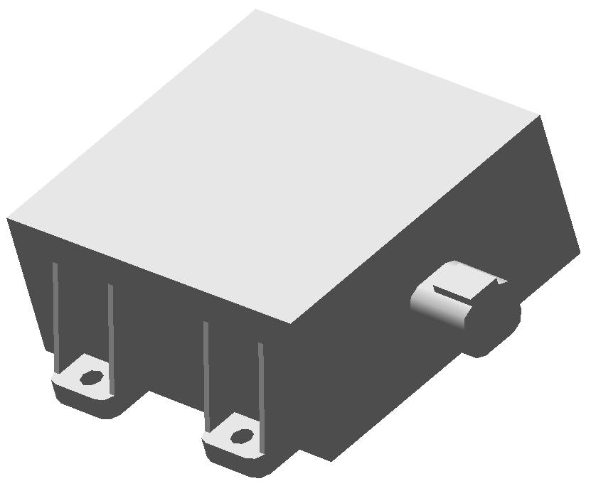
External stop relay
The engine is equipped with a relay that can be remotely controlled by third part equipment, e.g. a fire extinguishing system. The engine individually shuts down when the relay is energized.
NOTICE! Leave the external stop connector unconnected if the functionality is not to be used.
Fault codes presented on Vodia when external stop relay is activated:
MID 128, PPID 6, FMI 11
Engine control unit (EMS2)
The control unit checks and controls the unit injectors, to ensure that the correct volume of fuel is injected into each cylinder. It also calculates and adjusts the injection advance. Regulation is mainly done with the aid of the engine speed sensors and the combined sensor for air inlet pressure / intake manifold temperature.
The EMS2 system processor is located in the control unit, unit, protected from water and vibration.
The processor receives continuous information about:
• Engine Speed
• Throttle opening
• Oil pressure
• Oil temperature
• Crankcase pressure
• Air inlet pressure / intake manifold temperature
• Fuel pressure
• Fuel alarm, water in fuel
• Camshaft position
• Coolant level / oil level
• Coolant temperature
• Piston cooling pressure
The information provides information about current operation conditions and allows the processor to calculate the correct fuel volume, monitor engine status etc.
Sensor, crankcase pressure
The sensor that is measuring the crankcase pressure is located on the valve housing.
The sensor provides an output signal whose voltage is proportional to the pressure that the sensor measures.
The sensor is supplied with 5 Volt from the engine control module.
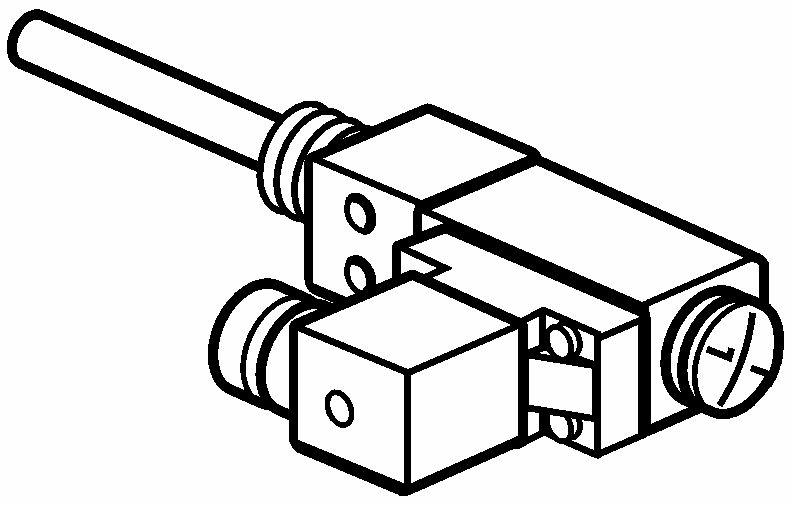
Switch, lube oil level (optional) (D9, D11, D12)
The switch is located on the left-hand side of the oil pan.
The switch can assume two states, on/off. When the oil level is correct, the monitor is on, i.e. a current flows to the EMS2.
1New model: Blue label (NC)
Old model: Black label (NO)
Oil level/temperature sensor (D9CC, D13, D16)
The sensor is located in the oil sump. The purpose of the level sensor is to detect if the oil level becomes too low. A current is passed through the sensor and the voltage measured across it is then proportional to the oil level. A alarm signal is sent when the oil level is too low. The temperature sensor consists of a non-linear resistor, where the resistance is dependent on the temperature of the resistor body. The resistance drops as temperature rises.
Switch, coolant level
The switch is located under the coolant expansion tank.
The level monitor comprises two parts, the actual monitor and a magnetic float built into the expansion tank. The monitor senses the position of the magnetic float. When coolant level drops, the float acts on the level monitor whose resistance drops to zero whereupon a circuit either closes (old model) or opens (new model).
NOTICE! When changing from a normally open (NO) switchtoanormallyclosed(NC)switch,makesurethat it is programmed in a correct manner. The EMS2 software must be upgraded.
The old switch has a black label and is NO. The new switch has a blue label and is NC.
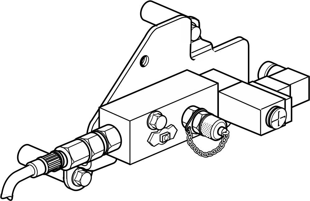
Water switch, secondary fuel filter
A switch is located underneath the secondary fuel filter in the water trap. Its task is to discover water in the fuel system.
The switch consists of two copper pins, between which resistance is measured. When the resistance falls below a limit value (which happens when water gets into the fuel), the control module receives an alarm signal.
Power Module
The Power Module is used on classified installations with a backup battery.
An electronic relay function on the Power Module regulates the power supply from the batteries onto the rest of the system. The Power Module also ensures that both batteries are connected and monitors the battery voltage.
The Power Module has a J1708/J1587 data link to communicate with the EMS2 and EVC/MCC. The Power Module monitors that the EMS2 and EVC/MCC is active.
The Power Module has auto fuses to prevent too high current from reaching the EMS2 (EMS supply), EVC/MCC (30 supply) and EasyLink (Extra supply).
DC/DC converter (only D9)
The DC/DC converter is used on engines with 12 V system voltage. The DC/DC converter retains sufficient power to the electrical system at crank. It also power supplies the system at normal operation.
Shutdown Unit (SDU)
The shutdown unit is an independent safety system to stop the engine in case of serious malfunction. The SDU is designed to fulfill all classification societies demands on safety system for propulsion engines and generator sets.
On D9 and D16 engines the SDU controls a fuel cutoff valve which activates in case of shutdown. D13 engines have a power relay that opens and cuts power to EMS2 in case of shutdown.
The sensors to the SDU are type approved switches for oil pressure, gear oil pressure and coolant temperature.
The switch level is designed to be activated after the EMS2 normal alarm and derate operation.
The SDU can be overridden and will therefore temporarily not shut down the engine if the operator activates this function. Over speed shut down is not affected and is always active. Overspeed pickup (unique sensor) is placed on the flywheel to measure over speeding of engine, 15% over nominal speed.
When replacing the SDU it must be configured manually. The SDU only consists of hardware, no software.
The SDU indicates status on its outputs. In an MCC system the SDU is connected to an MCU panel. In an EVC system the SDU is connected to an SDU panel.
SDU shutdown channels
Coolant temperature switch (S1)
(D9 CC, D13 CC, D16 CC)
Coolant temperature is monitored by a temperature switch. The temperature switch’s output signal can only indicate one of two positions, on/off, just like a relay output. A preset temperature limit determines when the switch switches from one distinct position to another.
Theswitch’spurposeistodetectifcoolanttemperature becomes too high.
Oil pressure switch, reverse gear (S2)
(D9 MH, D13 MH, D16 MH)
The oil pressure in the reverse gear is monitored by a pressure switch. The pressure switch’s output signal can only indicate one of two positions, on/off, just like arelayoutput.Apresetpressurelimitdetermineswhen the switch switches from one distinct position to another.
The switch’s purpose is to detect if the oil pressure in the reverse gear becomes too low.
Oil pressure switch, engine (S3)
(D9 CC, D13 CC, D16 CC)
The oil pressure in the engine is monitored by a pressure switch. The pressure switch’s output signal can only indicate one of two positions, on/off, just like arelayoutput.Apresetpressurelimitdetermineswhen the switch switches from one distinct position to another.
The switch’s purpose is to detect if the oil pressure in the engine becomes too low.
Coolant pressure switch (S4)
(not standard)
Coolant pressure is monitored by a pressure switch. The pressure switch’s output signal can only indicate one of two positions, on/off, just like a relay output. A preset pressure limit determines when the switch switches from one distinct position to another. The switch’s purpose is to detect if the coolant pressure becomes too low.
Oil temperature switch (S5)
(not standard)
Oil temperature in the engine is monitored by a temperature switch. The temperature switch’s output signal can only indicate one of two positions, on/off, just like a relay output. A preset temperature limit determines when the switch switches from one distinct position to another.
The switch’s purpose is to detect if the oil temperature in the engine becomes too high.
This channel could also be used as an extra emergency stop.
Exhaust temperature sensor (S6)
(not standard)
The sensor is placed in the exhaust bend after the turbocharger. Exhaust temperature sensor consists of a Pt-200 sensor. Its resistance changes depending on the temperature (the resistance increases with rising temperature).
The sensor’s purpose is to detect if the exhaust temperature is too high.
Sensor, engine rpm
The speed sensor is an inductive sensor, placed in the transmission gear casing. The sensor’s purpose is to detect overspeed.
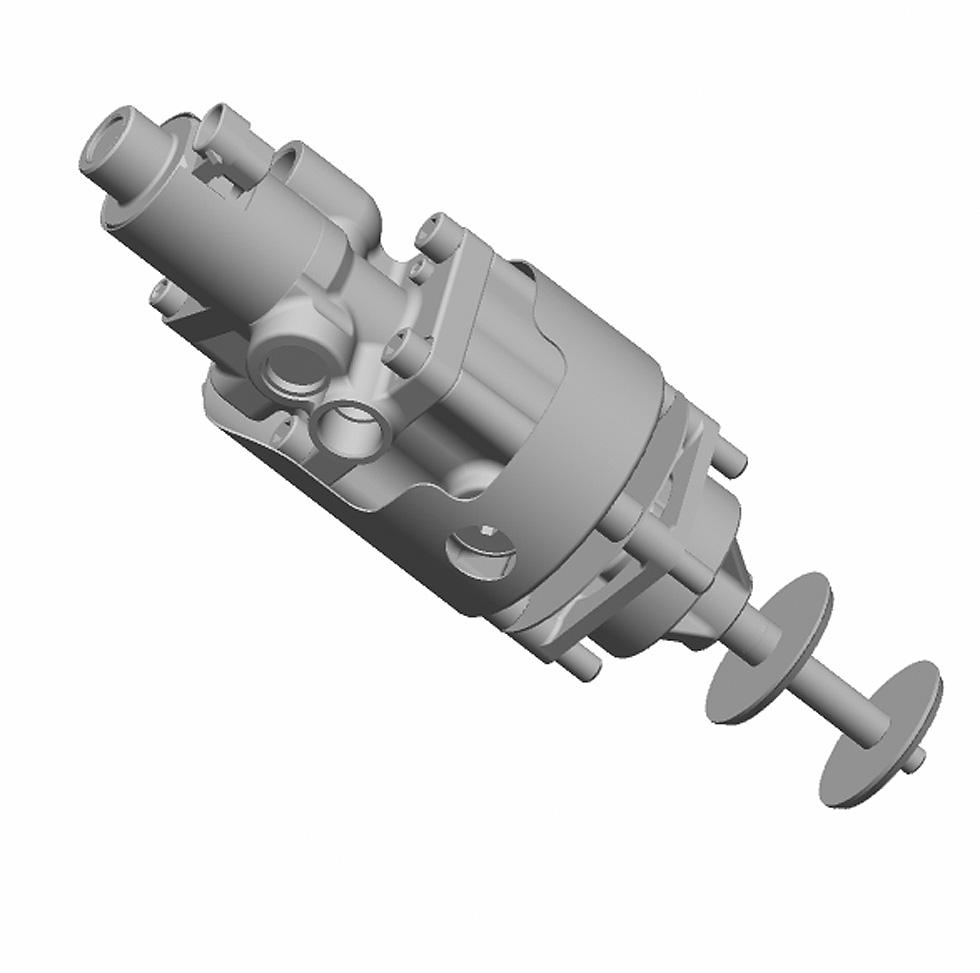
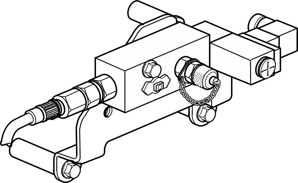
Fuel shut off valve
The valve is an electrical two directional valve. The valve position is controlled by a signal from the SDU. Whennosignalispresent,fuelfeedoperatesnormally. IfassignalisreceivedfromtheSDU,anelectromagnet is engaged, changing the valve position, thus stopping the fuel feed and shutting down the engine. When the valve is in normal operation mode the flow in the valve is P-T and F-I. When the valve is in shut down mode the flow alters to P-I and F-T.
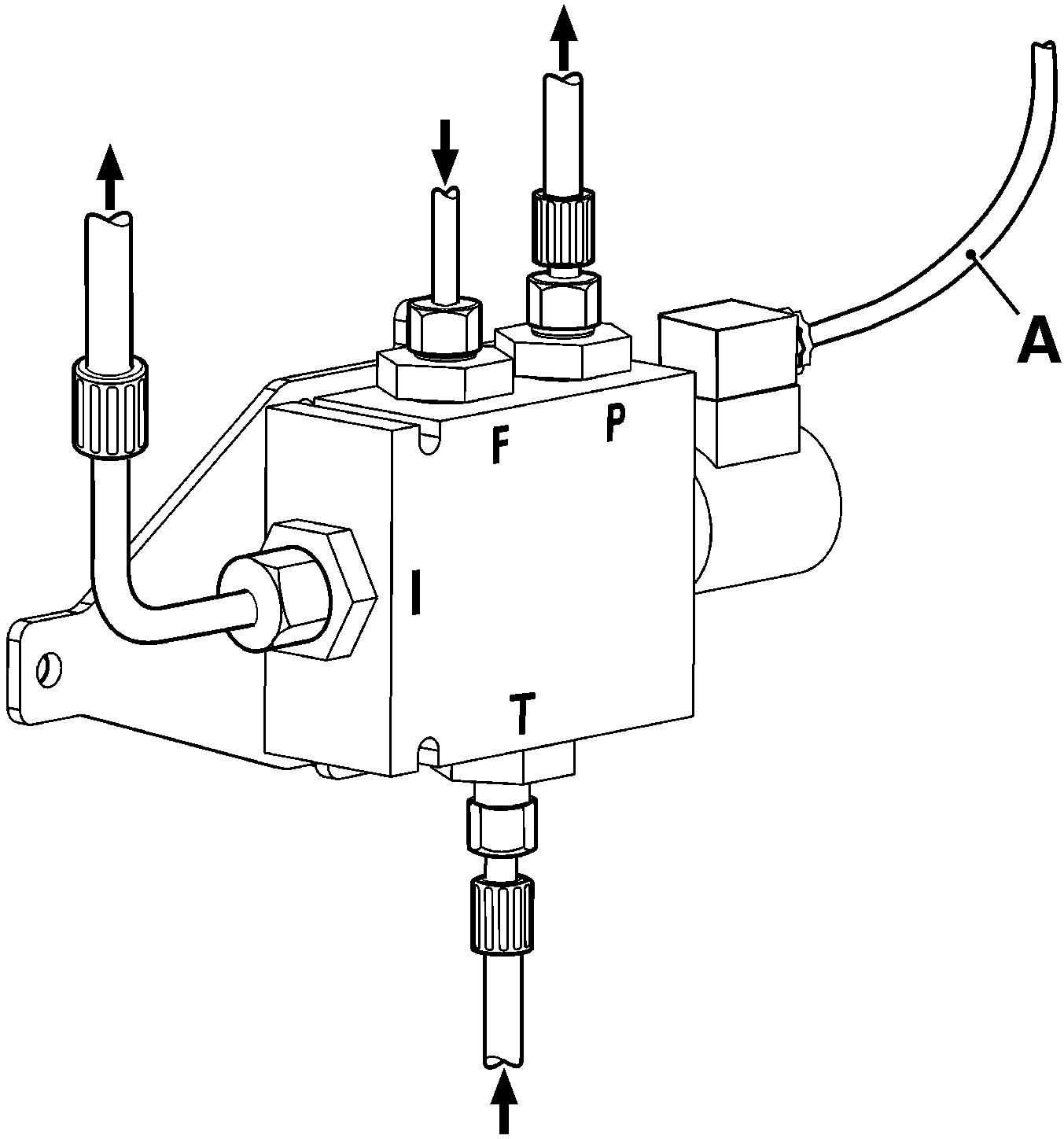
Connections in valve body, marking:
T. Inlet from fuel tank (Tank)
P. Outlet to feed pump (Pump)
F. Inlet from fuel filters (Filters)
I. Outlet to unit Injectors (Injectors)
A. Cable harness (Signal from engine protection unit)
P0018655
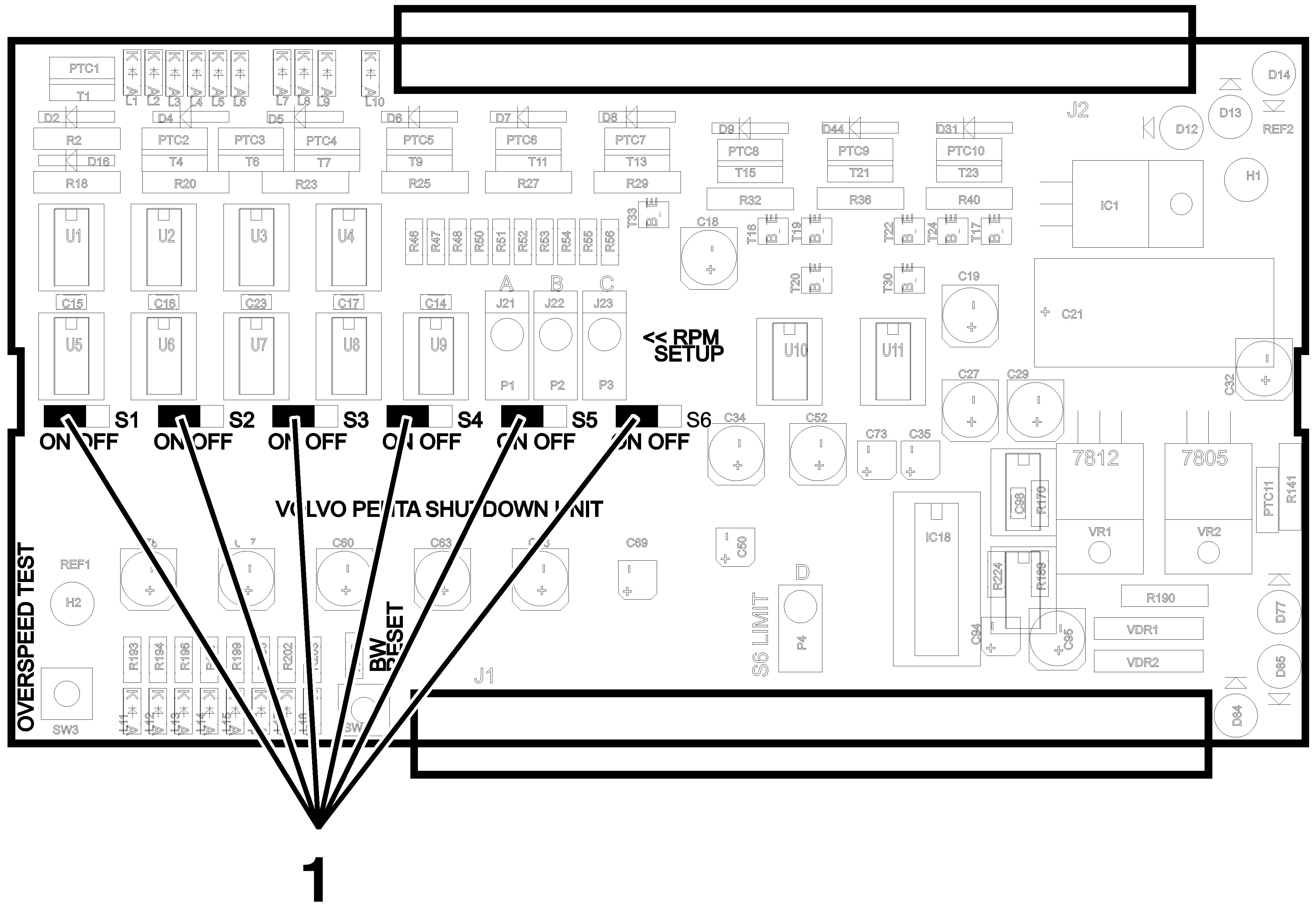
Channel set-up
1 Locate the channel on/off jumper pins (1) on the SDU card.
2Disable all the S1–S6 channels before configuring run detection and overspeed.
SDU adjustments
On Off On Off
P0018656
= Channel disabled = Channel enabled
1 = Channel On / Off jumpers
Switches/sensors, engine protection system
The respective switch or sensor shuts down the engine at the preset values found at section Engine Protection Map.
Channel Switch
S1. Coolant temperature
S2. Oil pressure, reverse gear(1)
S3. Oil pressure, engine(1)
S4. Coolant Pressure(2)
S5. Oil temperature, engine
S6. Exhaust temperature
1. ”Run detection S2, S3”
2. ”Run detection S4”
P0018657
Run detection configuration
Special tool: 88890074 Multimeter
Other special equipment: Frequency generator
The first configuration is for S2, S3 run detection.
NOTICE! Frequency (Hz) = rpm x pulses/revolution / 60
These values are found at section Engine Protection Map.
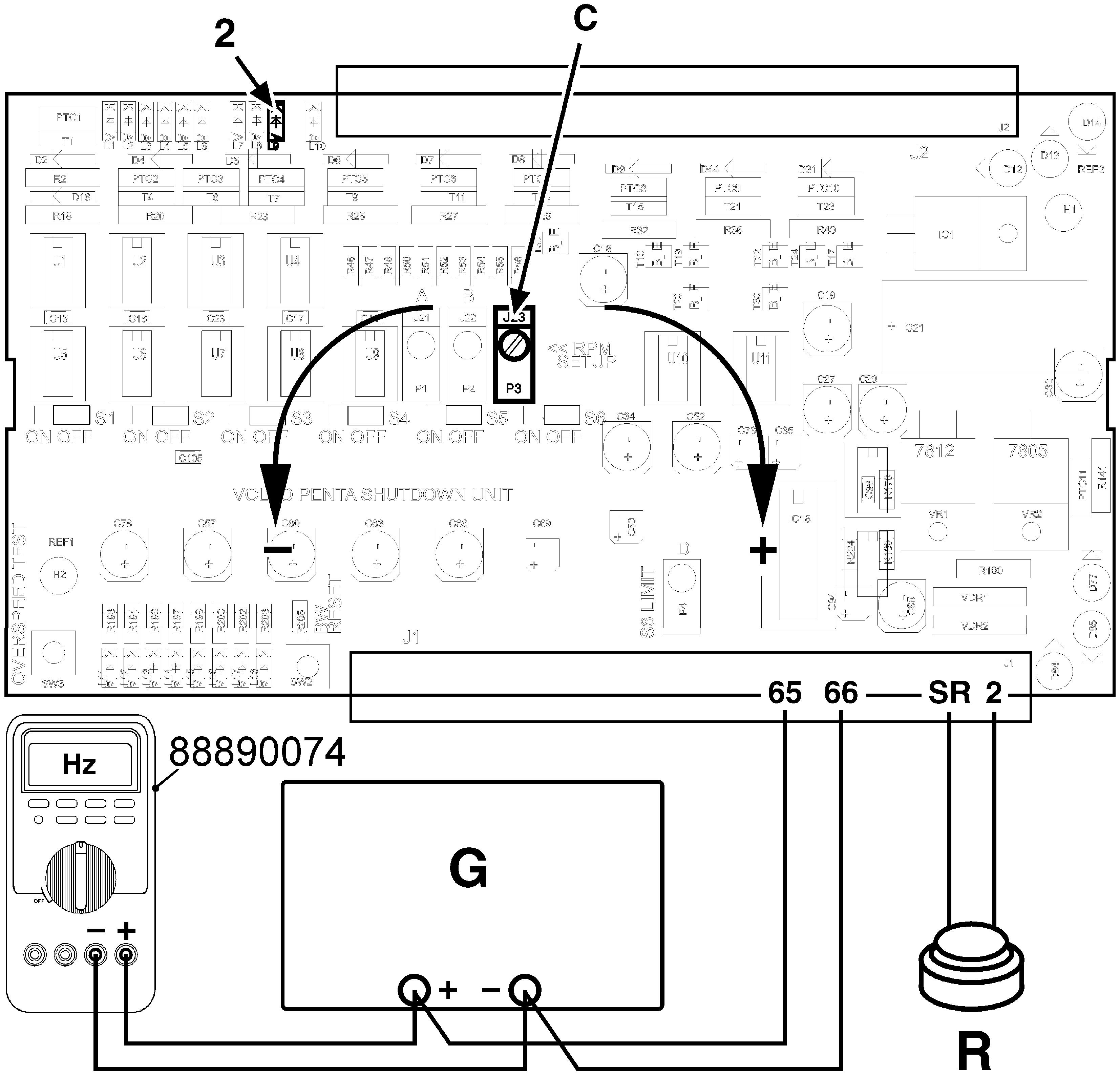
1 Connect terminal 1 to 24 V and terminal 2 to 0 V. 6 If the green LED (4) is not lit: Turn “A” counterclockwise (–), until the green LED is lit. The run detection limit is now configured.
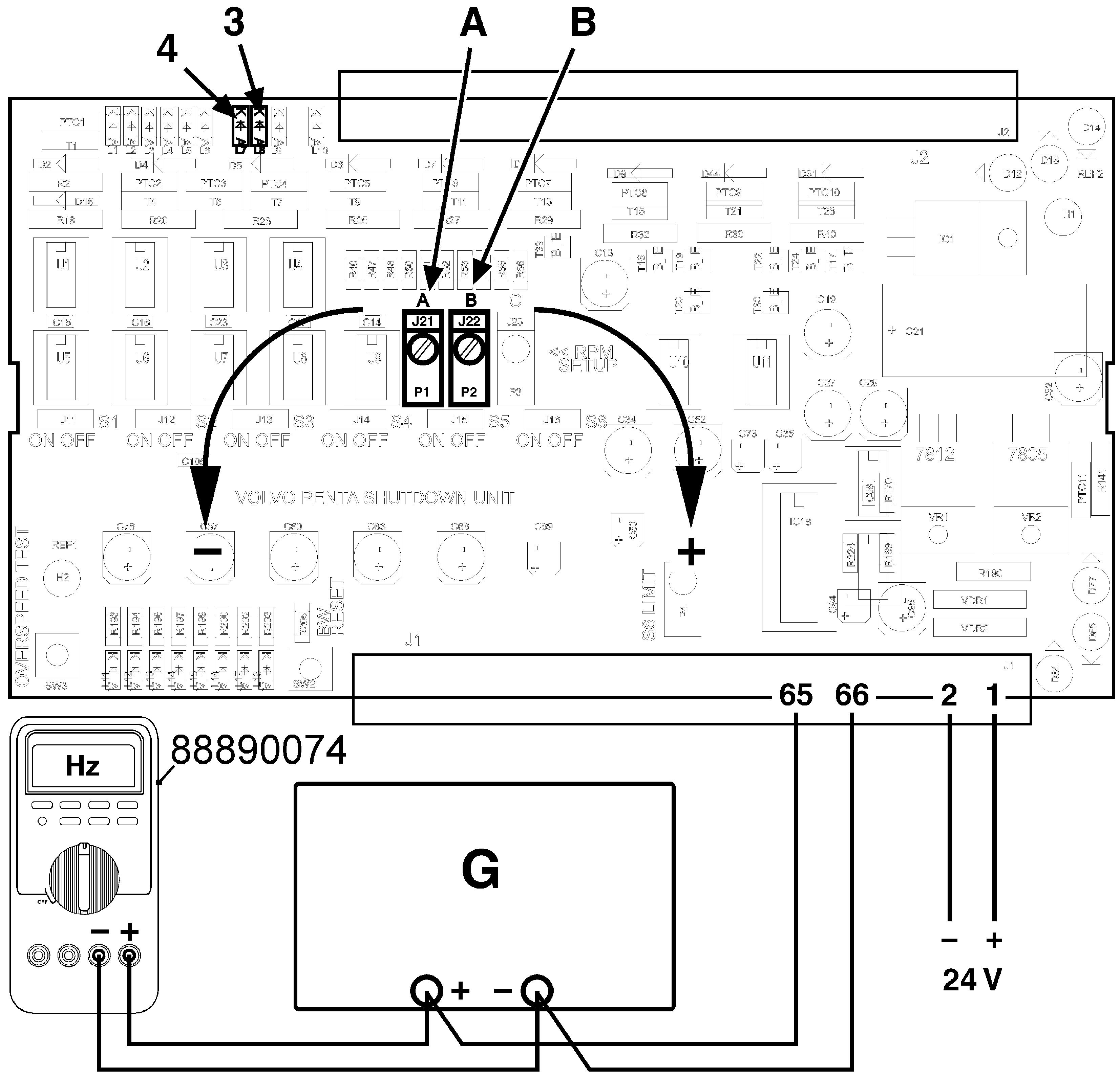
2 Switch on the supply and make sure the green LED(POWER)islitontheSDU.Somealarmscan be activated, ignore these.
3 Connect a sinusoidal frequency generator (G) to the 65, 66 inputs.
4 Connect 88890074 Multimeter in parallel with the frequency generator to measure the frequency.
5 Set the frequency generator to the run detection frequency.
If the green LED is lit: Turn “A” slightly clockwise (+) to switch off the LED. Then turn “A” counterclockwise (–) until the green LED is lit. The run detection limit is now configured.
7 Rampthefrequencyfrom0Hztotherundetection level to make sure that correct limit is configured.
8 MakethesameprocedurefortheS4rundetection (configure “B”). The S4 LED (3) color is yellow.
Overspeed configuration
Special tool: 88890074 Multimeter
Other special equipment: Frequency generator
If the red LED is lit: Keep the shutdown reset button (R) pushed and turn "C" slightly clockwise to switch off the LED. Release the shutdown reset button. Turn "C" counter-clockwise until the red LED is lit.
1 Connectthesinusoidalfrequencygeneratortothe 65, 66 inputs.
2 Connect 88890074 Multimeter in parallel with the frequency generator (G) to measure the frequency.
3 Set the frequency generator to the overspeed frequency seen in the table on the next page.
4 If the red LED (2) is not lit: Turn “C” counterclockwise until the red LED is lit.
5 Setthefrequencygeneratorto0Hzandthenpush the shutdown reset button (R).
6 Ramp the frequency from 0 Hz to the overspeed limit to make sure that correct limit is configured.
7 If the S6 channel is used, proceed with the exhaust temperature configuration.
8 Enable the channels S1–S6 according to the engine specification (refer to section “Channel set-up”). Fit the SDU cover.
Exhaust temperature configuration
Factory default setting for S6 is 650°C (~ 659 Ω) shutdown limit.
1Calibrate a variable resistor to a shutdown temperature value according to the table.
2Connect the configured resistor to the S6, 2 inputs.
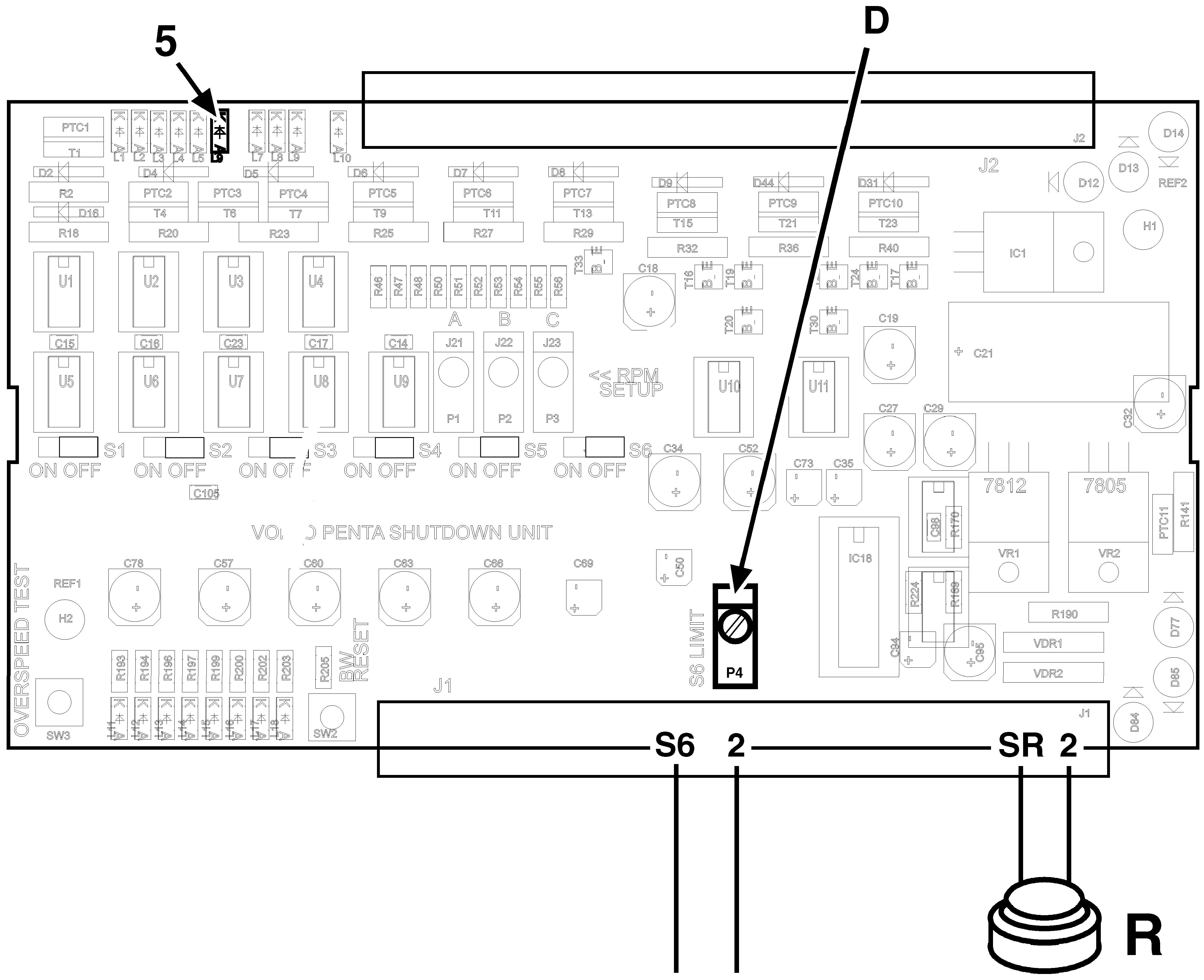
3Locate the variable resistor “D” and calibrate it until the S6 LED (5) is lit. – Turn counterclockwise to increase the shutdown limit. – Turn clockwise to decrease the limit.
4Reset with the shutdown reset button (R). Calibrate once more and then reset.
5Enable the channels S1–S6 according to the engine specification. Fit the SDU cover.
Engine Control Unit (ECU)
AEngine speed
BThrottle opening
COil pressure/-temperature
DAir inlet pressure / intake manifold temperature
ECrankcase pressure
FCoolant temperature
GDiagnostics
HCamshaft position
IFuel alarm, water in fuel
JFuel pressure
KCoolant level/oil level
LPiston cooling pressure
MChecking the wastegate control (D12)
NFuel volume
OInjection advance
Design and Function System Description EMS2
EMS2* is a system for electronic diesel engine control. The system has been developed by Volvo Penta and includes fuel control and diagnostic function.
* EMS= ”Electronic Management System”.
Control unit
The EMS system processor is located in the control unit, protected from water and vibration.
The processor receives continuous information about:
• Engine speed
• Throttle opening
• Oil pressure
• Oil temperature
• Crankcase pressure
• Air inlet pressure / intake manifold temperature
• Fuel pressure
• Fuel alarm, ”water in fuel”
• Camshaft position
• Coolant level/oil level
• Piston cooling pressure
The information provides information about current operation conditions and allows the processor to calculate the correct fuel volume, monitor engine status etc.
Fuel control
The amount of fuel injected into the engine and the injection advance are fully electronically controlled, via fuel valves and the unit injectors, once the control unit has analyzed the engine’s fuel requirements. Thismeansthattheenginealwaysreceivesthecorrect volume of fuel in all operating conditions, which offers lower fuel consumption, minimal exhaust emissions etc.
The control unit checks and monitors the unit injectors to ensure that the correct volume of fuel is injected into each cylinder, and it calculates and adjusts the injection advance. Regulation is mainly done with the aid of the engine speed sensors and the combined sensor for air inlet pressure / intake manifold temperature.
The control unit controls the unit injectors via a signal to the electromagnetically operated fuel valve in each injector, which can be opened and closed.
When the fuel valve is open, fuel flows through the holes in the unit injectors and out through the fuel duct. Fuel is not injected into the cylinders in this phase. When the fuel valve is closed, pressure is built up by the mechanically driven pump piston in the unit injector. When enough pressure has been built up, fuel is injected into the cylinder via the nozzle part of the unit injector.
The fuel valve is re-opened and pressure in the unit injector falls at the same time as fuel injection to the cylinder ceases.
The control unit receives signals from various sensors on the engine, which allow it to decide when the fuel valve should be opened and closed.
Calculation of fuel quantity
The quantity of fuel to be injected into the cylinder is calculated by the control unit. The calculation gives the time when the fuel valve is closed (fuel is injected into the cylinder when the fuel valve is closed).
The parameters which govern the amount of fuel injected are:
• Demanded engine speed
• Engine protection functions
• Intake manifold temperature
• Air inlet pressure
Normal start
Boththecamshaftsensorandflywheelsensorfunction normally. The engine is cranked until the engine control unit discovers that cylinder 1 is next in line for injection. Fuel is injected and the engine starts.
Starting without the camshaft sensor
If the engine control unit discovers that the camshaft signal is not available, the engine control unit will still attempt to start the engine. When the engine control unit detects a break in the pulse train from the flywheel sensor, one of the cylinders is in the position for injection, but the engine control unit does not know which one. The engine control unit guesses which cylinder is next in line, and injects fuel at the same time as it monitors engine speed to see if it increases. If engine speed does not increase, the guess was wrongandtheenginecontrolunittriesagain.Itwilltake a bit longer time to start the engine, but it will start with no problems apart from setting a fault code.
Starting without the flywheel sensor
If the engine control unit discovers that the flywheel signal is not available, the engine control unit will still attempt to start the engine. Injection will be monitored using information from the camshaft sensor. Injection will not be as exact as normal, and the engine will have reduced power.
If the engine starts, idling speed will be unstable. The engine control unit will not be able to do any cylinder balancing.
Cylinder balancing
During idling, the control unit can provide the cylinders with different amounts of fuel. This is to give the engine moreevenidling.Athigherenginespeeds,allcylinders receive the same amount of fuel.
Diagnostic Function
The EMS system has a built-in diagnostic function which can discover any faults in the engine and sensors.
The function of the diagnostic function is to discover and localize any function faults in the EMS system, to protect the engine and guarantee continued operation if a serious function fault should occur.
Idling adjustment (low idle)
Idling speed can be adjusted to a value between 500–750 rpm.
Repair Instructions
General advice on working with EMS engines
The following advice must be followed to avoid damage to the engine control unit and other electronics.
IMPORTANT!
The system must be switched off and the system current disconnected when any of the connectors on the engine control unit is connected or disconnected.
•Never disconnect the current with the main switches when an engine is running.
•Never undo a battery cable when the engine is running.
•Turn the main switches off or disconnect the battery cables during quick charging of the batteries.
NOTICE!During normal trickle charging, it is not necessary to turn the main switches off.
• Only batteries may be used for start help. A help startdevicecanproduceaveryhighvoltageand damage the control unit and other electronics.
•If damage is discovered in a cable harness the two 36-pin connectors for the enginecontrol unit andthe8-pinconnectorbetweentheengineand the EVC system must be disconnected.
• If a connector is disconnected from a sensor, be very careful to avoid allowing the contact pins to come into contact with oil, water or dirt.
Electrical Welding
IMPORTANT!
Undoallconnectorsfromtheenginecontrolunitbefore you start electric welding.
IMPORTANT!
Cut the engine current before the control unit connector is disconnected.
Cut the current with the main switches. Then disconnect all connections to the alternator.
Undo the connector from the engine control unit and from the power supply unit.
Please refer to more detailed instructions in the ”Workshop manual group 21–26, ”Control unit, changing”.
Connect the welder earth clamp to the component to be welded, or as close as possible to the weld site. The clamp must never be connected to the engine or in such a way that current can pass through a bearing.
IMPORTANT!
After welding is completed, the disconnected components, such as alternator cables and battery cables must be connected in the correct order.
Fault tracing of cables and connectors
Special Tools: 9812519, 9998482.
Check all connectors visually
Check the following:
•Look for oxidation, which can impair contact in connectors.
•Check that terminals are undamaged, that they are correctly inserted into their connectors, and that the cable is correctly terminated in the terminal.
•Check that there is good mechanical contact in the connector. Use a loose pin to check this.
IMPORTANT!
The multi-pin connectors for the engine control unit must only be checked with gauge 9998482.
• Carefully insert gauge 9998482 into the multipin connector. Pull and push the connector in and out a few times and feel whether the terminal socket grasps the tool. If the terminal socket doesnotgrasp,orifitfeelsslack,theconnection pinsshouldbechanged.Pleasereferto”Joining electrical cables for multi-connector” Check the secondary locking in the connector.
Contact problems
Intermittent contact or temporary recurring faults can be difficult to fault trace, and are frequently caused by oxidation, vibration or poorly terminated cables.
Wear can also cause faults. For this reason, avoid disconnecting a connector unless it is necessary. Other contact problems can be caused by damage to pins, sockets and connectors etc.
Shake cables and pull connectors during measurement, to find where the cable is damaged.
Contact resistance and oxidation
Resistance in connectors, cables and junctions should be close to 0 Ω. A certain amount of resistance will occur, however, because of oxidation in connectors.
If this resistance is too great, malfunctions occur. The amount of resistance that can be tolerated before malfunctions occur varies, depending on the load in the circuit.
Open circuit
Possible reasons for faults could be chafed or broken cables, or connectors which have come undone.
Use the wiring schedule to check the cable harnesses which are relevant to the function. Start off with the most probable cable harness in the circuit.
Check the following:
•Disconnect the relevant connector at each end of the cable harness.
•Use multimeter 9812519 to measure the resistance between the ends of the cable. Nominal value close to 0 Ω.
•If possible, shake the cables and pull the connectors during measurement to discover whether the cable harness is damaged.
•Check that the cables are not damaged. Avoid clamping cables in tight bends close to the connector.
•Check the function of the secondary locking.
•If possible, shake the cables and pull the connectors during measurement to discover whether the cable harness is damaged.
•Check the next cable harness in the wiring schedule if no fault has been found.
P0008528 P0008529 P0008530
Connection of 9998699 Break-out box to EMS2
Special Tools: 9990014, 9998699.
1 Dismount the engine control unit by loosen the 4 bolts.
2 Loosen the clamps to the connectors.
4 Connect the engine control unit connector to the brakeout cable 9990014 (1). Connect the brakeoutcable9990014totheenginecontrolunit (2).
All pins from the engine control unit is accessible in the measurebox 9998699.
Fault tracing of the starter motor and windings
Special Tools: Multimeter 9812519.
General
If battery voltage falls below 24.7 V (measured at the battery), the starter motor will not be able to crank the engine at normal speed. A fully charged battery has an open circuit voltage of about 25.4 V.
Checking the power supply
1 Check that the battery voltage is at least 24.7 V unloaded, by measuring the battery terminals with multimeter 9812519.
2 Turn on the main switch.
3 Check that the voltage between positions 30 and 31 on the starter motor is the same as the battery voltage.
Checking the charging system
Special Tools: 9812519.
Generally about alternators: The voltage output from an alternator must be limited to prevent the elecrolyte in the battery to evaporate. The alternator output is regulated (limited) by the voltage regulator in the alternator. The maximum current that the alternator can deliver at regulated voltage output depends on the alternator revolution. To make the alternator charging more efficient a sense cable between the alternator and the battery+ can be added to compensate if there is a voltage drop in the cable between the alternator and the battery+.
When the engine is started an excitation current is needed to “wake up” the alternator. NOTICE! It is the consumers (batteries included) which decides the output current from the alternator.
Measurements
1Engine off.
2Use multimeter 9812519 to do a voltage measurement over the battery. The nominal voltage over a full loaded battery is approx. 12.6V or 25.2V.
3Engine on. Run at 1500 rpm.
4Use multimeter 9812519 to do a voltage measurement over the battery. The nominal charging voltage over the battery should be approx.13.6–14.4Vor27.8–28.6V(ifthesense cable is connected).
Fault tracing the charging system
Battery
1Check that all connectors at the battery is correctly assembled.
2 Checktheconditionsofthecablestothebattery.
3Check the water level in the battery.
4 Check,ifpossible,thespecificgravityofallcells. when no charge when undercharge when overcharge
1Check the alternator belt tension.
2Check that all connectors at the alternator and at the battery is correctly assembled.
3 Check the condition of all cables in the charging system.
4Check the brushes length and condition.
5Change, if possible, the regulator.
1Check the alternator belt tension.
2Check that all connectors at the alternator and at the battery is correctly assembled.
3 Check the condition of all cables in the charging system.
4Check the brushes length and condition.
5Change, if possible, the regulator.
1Change, if possible, the regulator.
P0008398 P0008399
Checking alternator brushes
Alternator brush removal
Valid for alternator 3587218 and 3840182.
1 Pull out the black plastic lid.
P0008405
2 Use a screwdriver to snap of the plastic lid over the brush holders.
3 Disassemble the two torx screws that holds the two brush holders.
5 If the brush is worn beyond the wear limit line, 5 mm (0.2"), it must be replaced.
Alternator brush installation
1 Take care to that the brushes are placed according to the illustration when installing.
Alternator faulttracing
Valid for alternator 20409228.
• NOTICE! Cut the current with the main switch.
• Remove all connectors on the alternator. B+, B–, etc.
• Removetheplasticcoveroverthediods.Theplastic cover is fixed with two nuts on B1+, B2+, and a pozidrive screw.
• Loosen the three screws that holds the brushes and the regulator.
Checking the brushes
Measure the length of the brushes between the brush mating surface and the brush holder. If any brush is damaged the brushes should be replaced.
Checking the regulator
• Set the multimeter 9812519 to diode measurement.
• Connect the probes between the brushes. Check that there is no short circuit.
• Switch the probe points and check that there is no short circuit.
• NOTICE! If a regulator fault is suspected install a new regulator and test run the charge system.
Checking the rotor
• Set the multimeter 9812519 to diode measurement.
• Connect one probe to each slip ring. The multimeter should show low resistance but not 0 ohm (short circuit) or infinity (open circuit).
• Checkthattheslipringsdonothaveanyburnmarks or other damage.
Short circuit test the rotor
• Set the multimeter 9812519 to diode measurement.
• Connect the probes between one of the slip rings and the stator body. The multimeter should indicate OL otherwise the rotor has a short circuit.
Energizing sequence
1 When the main switch is closed, the engine control unit pin A8 (main relay hold) gets battery potential. Main relay is not activated. The PCU and HCU are energized (via the engine connector pin 4).
2 When the starter key is turned to position I (terminal 15a on the starter switch is connected topin30),theenginecontrolunitpinA58receives an activation signal from the PCU via pin 5 in the engine connector. Pin A8 alter its potential to approx. 0.8 V and the main relay activates. When the ignition is switched, the EVC equipment such as the control panels and instruments are activated. All relays connected to the starter switch and start / stop panels are activated to supply current to equipment which does not belong to the EVC.
Changing the engine control unit
1 NOTICE! Cut the current with the main switch.
IMPORTANT!
The system must be disconnected from system voltage when the engine control unit connectors are disconnected or connected.
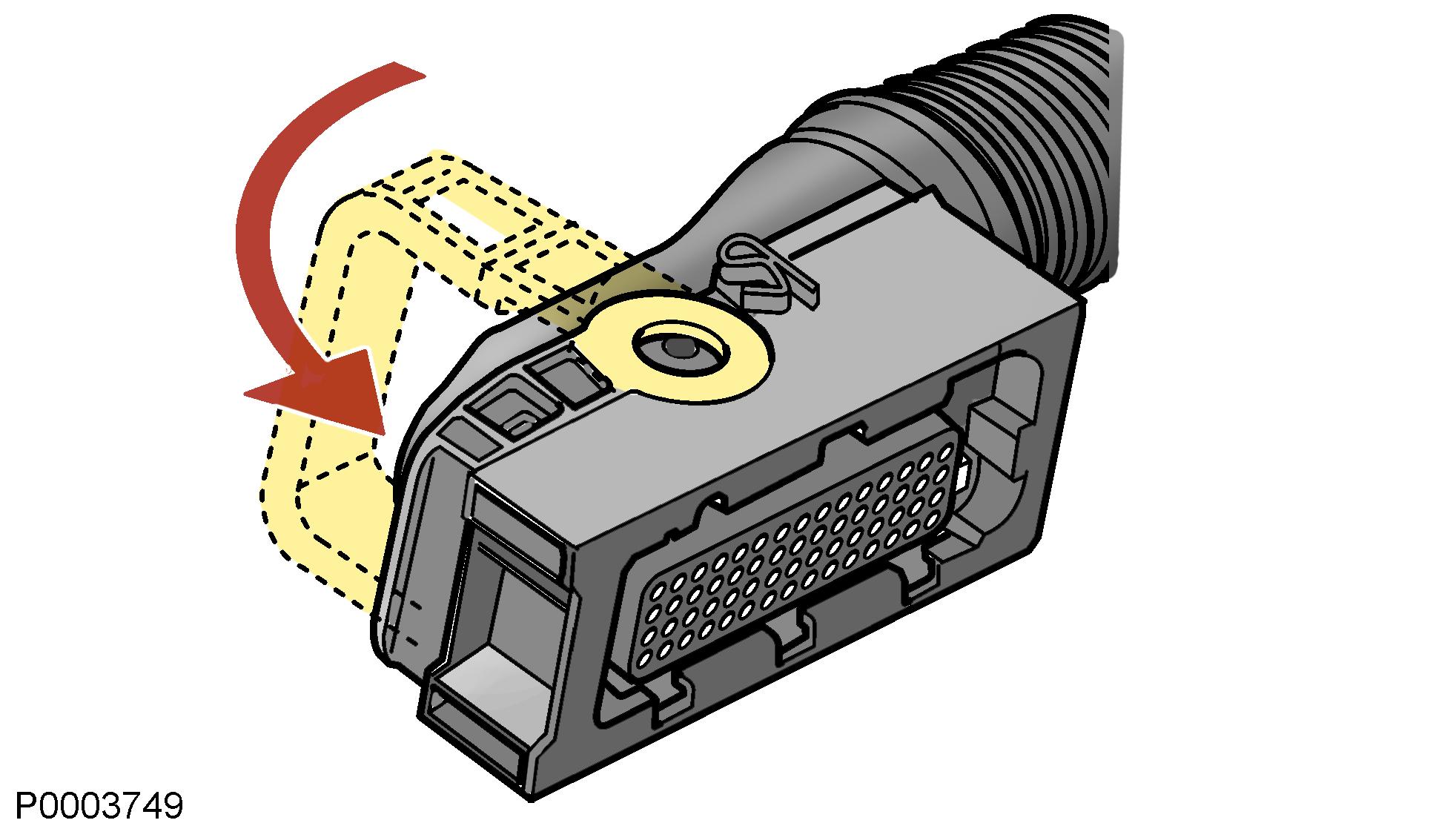
2 Removethetwoconnectorsfromtheenginecontrol unit. Turn the locking arm down at the same time as the connector is pulled outwards.
3If the new engine control unit has recently been programmed: Start the engine and check if there are any faults.
Changing control unit
Programming the control unit
IMPORTANT!
The chassis number or engine serial number must be available to allow the software to be downloaded.
Action:
1Log in to Volvo Penta Partner Networks web site, http://www.vppn.com
2Choose ”Vodia” in the left-hand menu.
3Choose ”ECU Programming” in the left-hand menu.
4 Follow the instructions under ”Download software”. Choose the control units to be re-programmed and click the ”Download” button. The software for the selected control units is now downloaded to the PDA (Personal Digital Assistant).
5Take a look under ”Settings”, ”Software information” in Vodia to check that the software has been downloaded.
6Connect the Vodia to the engine to be programmed.
7Start with the engine control unit. Select ”Engine with mounting and equipment” in the Vodia menu. Select ”MID 128 Control unit, programming”. Vodia will guide you through the entire programming process.
8 The next control unit is the vehicle control unit, PCU (Powertrain Control Unit). Select ”Electrical system and instruments” in the Vodia menu. Select ”MID 187 Control unit, programming”. Vodia will guide you through the entire programming process.
9 The next control unit to be programmed is the HCU (helm station control unit). Select ”Electrical system and instruments” in the Vodia menu. Select ”MID 164 Control unit, programming”. Vodia will guide you through the entire programming process.
NOTICE! All helm station control units on the same drive line should be programmed in one sequence.
NOTICE! Auto-configuration must be done when programming is finished.
10 Programming must be reported back to Volvo within 28 days. Log in to Volvo Penta Partner Networks web site, http://www.vppn.com
11Choose ”Vodia” in the left-hand menu.
12Choose ” Report software” in the left-hand menu.
13Follow the instructions for ”Report software/parameter”. Click ”Report software/parameter”.
Programming an empty control unit
When an ”empty” engine control unit is installed, where no software is programmed, the control unit must be programmed. If the new control unit is to replace an existing control unit, the control units must have the same part number. If the control units do not have the same part number, it will not be possible to program the new control unit until a ”Conversion kit” has been ordered from Volvo Penta. If the control units have the same part number, the new control unit can be programmed as usual, please refer to “Programming the Control Unit”.
If the part numbers are not the same, do as follows:
1Have both part numbers available.
2Log in to Volvo Penta Partner Networks web site, http://www.vppn.com
3Choose ”Vodia” in the left-hand menu.
4Choose ”Conversion kit” in the left-hand menu. A new page, ”Conversion kit / Accessory kit”, opens up.
5Click the text ”Available conversions kits” which is shown in bold face. Follow the instructions described in the window.
6Return to the ”Conversion kit / Accessory kit” page and follow the instructions to order a new ”Conversion kit”.
7 Volvo Penta’s computer system is now updated. This may take a minute or so before a confirmation is sent back.
8Programming of the control unit can now be done, please refer to “Programming the Control Unit”.
Fault code information
• MID (“Message Indication Description”): The MID consists of a number which designates thecontrolunitthatsentthefaultcodemessage. (e.g. the engine control unit).
• PID (“Parameter Indication Description”): The PID consists of a number that designates a parameter (value) to which the fault code relates (oil pressure, for example).
Function fault
• SID (“Subsystem Indication Description”): The SID consists of a number that designates a component to which the fault code relates (tachometer, for example).
• PSID (“Proprietary SID”)
The same as the SID, but this is a Volvo-specific component.
• FMI (“Failure Mode Identifier”):
• PPID (“Proprietary PID”):
The same as the PID, but this is a Volvo-specific parameter.
FMI indicates the type of fault (please refer to the FMI table below). FMI table – SAE-standard
Volvo-specific for injectors (MID 128, SID 1-6)
NOTICE! The following must be done before fault tracing continues, to avoid changing functional sensors:
• If there is an active / inactive fault code
Remove the connector from the sensor. Check that there is no oxidation and that the connector pins are not damaged. If there is a fault, please refer to ”Fault Tracing the Cables and Connectors”.
NOTICE! Some fault codes become inactive when the engine is stopped. Start the engine to check whether the fault code is still inactive with the engine running.
• After an action with the connector
Put the connector* back. Check if the fault code becomes inactive. If the fault remains, measure the cables and sensors to check them, as instructed.
NOTICE! * No grease in the connector.
Problems in identifying the engine control unit (MID 128)
In normal cases, VODIA identifies the engine control unit (MID 128) and the PCU (MID 187) automatically when the choice of engine installation is done.
The HCU must be in service mode to allow it to be identified.
If VODIA is not able to identify the engine control unit (MID 128), this will not be visible under ”Vehicle information”.
NOTICE! If the engine control unit has not been identified, it can not be programmed.
One reason why identification can not be done is that the PCU contains the wrong engine software or that the J1708A and J1708B data buses between the engine control unit and the PCU are short circuited to each other. In this case, Vodia can not identify a control unit.
Stop
The system can not be shut down although the starter key is turned to position 0. This can be caused by a short circuit in the cables betweentheHCUandthekeyswitch,byashortcircuit in the key switch or a fault in the stop/start panel.
Shut the system off with the AUX stop button.
The starter motor is activated with the ignition on. If the starter motor is activated as soon as the switch is turned, the diode in the key switch cable harness might be short circuited. Fault trace the diode in accordance with the ”Checking the key switch diode” section.
