11 minute read
System Description

from Volvo Penta 4.3GXi, 4.3OSi5.0GXi, 5.0OSi5.7Gi, 5.7GiI 5.7GXi, 5.7GXiI 5.7OSi, 5.7OSXi8.1Gi, 8.1GiI,
Section 2: System Description
Visual / Physical Inspection . . . . . . . . . . . . . . . . . . . . . . . . . . . 29 Basic Knowledge and Tools Required . . . . . . . . . . . . . . . . . . 29 Electrostatic Discharge Damage . . . . . . . . . . . . . . . . . . . . . . . 29 Engine Wiring . . . . . . . . . . . . . . . . . . . . . . . . . . . . . . . . . . . . . . 30 Engine Control Module (ECM) Self-Diagnostics . . . . . . . . . . 30 Malfunction Indicator Lamp (MIL) . . . . . . . . . . . . . . . . . . . . . . 30 Intermittent Malfunction Indicator Lamp (MIL) . . . . . . . . . . . . 30 Reading Diagnostic Trouble Codes (DTC’s) . . . . . . . . . . . . . 31 Service Mode . . . . . . . . . . . . . . . . . . . . . . . . . . . . . . . . . . . . . . . 32
Normal Mode . . . . . . . . . . . . . . . . . . . . . . . . . . . . . . . . . . . . . . . 32
On-Board Diagnostic (OBD) System Check . . . . . . . . . . . . . . 32 DLC Scan Tools . . . . . . . . . . . . . . . . . . . . . . . . . . . . . . . . . . . . 32
Special Tool and Equipment . . . . . . . . . . . . . . . . . . . . . . . . . . . . 33
Visual / Physical Inspection
A careful visual and physical inspection must be performed as part of any diagnostic procedure. This can often lead to fixing a problem without further diagnostics. Inspect all vacuum hoses for correct routing, pinches, cracks or disconnects. Be sure to inspect hoses that are difficult to see. Inspect all the wires in the engine compartment for proper connections, burned or chafed spots, pinched wires or contact with sharp edges or hot manifolds. This visual/physical inspection is very important. It must be done carefully and thoroughly.
Basic Knowledge and Tools Required To use this manual most effectively, a general understanding of basic electrical circuits and circuit testing tools is required. You should be familiar with wiring diagrams, the meaning of voltage, ohms, amps and the basic theories of electricity. You should also understand what happens if a circuit becomes open, shorted to ground or shorted to voltage. To perform system diagnostics, several special tools and equipment are required. Please become acquainted with the tools and their use before attempting to diagnose the system. Special tools that are required for system service are illustrated in this section.
Electrostatic Discharge Damage Electronic components used in control systems are often designed to carry very low voltage, and are very susceptible to damage caused by electrostatic discharge. It is possible for less than 100 volts of static electricity to cause damage to some electronic components. By comparison, it takes as much as 4,000 volts for a person to feel the zap of a static discharge. There are several ways a person can become statically charged. The most common methods of charging are by friction and by induction. An example of charging by friction is a person sliding across a seat, in which a charge of as much as 25,000 volts can build up. Charging by induction occurs when a person with well insulated shoes stands near a highly charged object and momentarily touches ground. Charges of the same polarity are drained off, leaving the person highly charged
Engine Wiring
Engine Control Module (ECM) SelfDiagnostics
with the opposite polarity. Static charges of either type can cause damage. Therefore, it is important to use care when handling and testing electronic components.
When it is necessary to move any of the wiring, whether to lift wires away from their harnesses or move harnesses to reach some component, take care that all wiring is replaced in its original position and all harnesses are routed correctly. If clips or retainers break, replace them. Electrical problems can result from wiring or harnesses becoming loose and moving from their original positions, or from being rerouted.
The Engine Control Module (ECM) performs a continuous self-diagnosis on certain control functions. This diagnostic capability is complemented by the diagnostic procedures contained in this manual. The ECM’s language for communicating the source of a malfunction is a system of Diagnostic Trouble Codes (DTC’s). The DTC’s are two digit numbers that can range from 12 to 81. When a malfunction is detected by the ECM, a DTC is set and the Malfunction Indicator Lamp (MIL) is illuminated.
Malfunction Indicator Lamp (MIL) The Malfunction Indicator Lamp (MIL) is part of the Diagnostic Trouble Code (DTC) tool, or it can be a dash mounted warning light on some applications. •If present, it informs the operator that a problem has occurred and that the boat should be taken for service as soon as reasonably possible. •It displays DTC’s stored by the ECM which help the technician diagnose system problems. As a bulb and system check, the light will come “ON” with the key “ON,” engine “OFF.” When the engine is started, the light will turn “OFF.” If the light remains “ON,” the self-diagnostic system has detected a problem. If the problem goes away, the light will go out in most cases after 10 seconds, but a DTC will remain stored in the ECM. When the light remains “ON” while the engine is running, or when a malfunction is suspected due to a driveability problem, the “On-Board Diagnostic (OBD) System Check” must be performed as the first step. These checks will expose malfunctions which may not be detected if other diagnostics are performed prematurely.
Intermittent Malfunction Indicator Lamp (MIL)
In the case of an “intermittent” problem, the Malfunction Indicator Lamp (MIL) may light for 10 seconds, and then go out. However, the corresponding DTC will be stored in the memory of the ECM. When DTC’s are set by an intermittent malfunction, they could be helpful in diagnosing the system. If an intermittent DTC is cleared, it may or may not reset. If it is an intermittent failure, consult the “Diagnostic Aids” on the facing page of the corresponding DTC table. A physical inspection of the applicable sub-system most often will resolve the problem.
Reading Diagnostic Trouble Codes (DTC’s)
1 4
5 8 Data Link Connector
23822 The provision for communicating with the ECM is the Data Link Connector (DLC). It is part of the engine wiring harness, and is a 8-pin connector, which is electrically connected to the ECM. It is used in the assembly plant to receive information in checking that the engine is operating properly before it leaves the plant. The DTC(s) stored in the ECM’s memory can be retrieved with several Diagnostic Trouble Code (DTC) tools listed below.
VODIA Scan Tool The VODIA tool is an advanced flexible diagnostic tool which is compatible with all Volvo Penta Gas and Diesel engines with electronic control systems, including the new EGC Control System. The VODIA tool is a full-feature scan tool which will read and record all vital engine parameters, read and reset fault codes, and perform engine tests. The tool will also allow access to EVC systems and links to the Volvo Penta Partner Network where updates can be downloaded online for future expansion. The VODIA tool may only be ordered through the Volvo Penta Partner Network. From the home page, select Service/Warranty and then select VODIA from the menu. Detailed information and pricing may be found on the VODIA website. Dealers who currently have a VODIA tool can order the connection cable for EGC engines (PN 3883170) from our Parts and Accessories department. The program itself is available for download to all registered users from the VODIA website on the Volvo Penta Partner Network.
VODIA
MEFI
iPAQ
EDC4
PocketPC PocketPC 23859
Volvo Penta Marine Diagnostic Scan Tool (P/N 3851228)
MarineDiagnosticScanTool Marine Diagnostic Scan Tool
ForComputerControlledFuelInjectionSystems For Computer Controlled Fuel Injection Systems
PAUSE SETUP TEST YES
NO
HELP
23852 This full-function scan tool will: •Provide complete access to all vital engine parameters. •Read and reset fault codes. •Perform output tests on EGC Control Systems. The tool is also compatible with all GM based Volvo Penta EFI engines with MEFI 1, 3, 4, and 4B controls. The tool features an easy to use keypad and a high visibility two line text display. The kit includes connectors for EGC and MEFI engines, and a carrying case. Updates Dealers who currently have earlier versions of this tool with the Techmate faceplate can obtain updated internal software and a connection cable by contacting Rinda Technologies, Chicago, IL, at (773) 7366633 or by visiting http://www.rinda.com
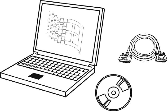
Diacom PC Software The Diacom program will provide full access to all vital engine parameters, read and reset fault codes, and perform output tests on EGC Control Systems. The program allows easy access to all vital engine parameters on Windows based PC’s. Fault codes can be read and reset, and output tests can be performed. The system can easily record and store test runs. Live or recorded readings may be graphed for analysis and can also be e-mailed to VPA Technical Assistance for review. The software is also compatible with all Volvo Penta General Motors based EFI engines with MEFI 1, 3, 4, and 4b controls. The kit includes connectors for EGC and MEFI engines and may be purchased directly by contacting Rinda Technologies, Chicago, IL, at (773) 736-6633 or by visiting http://www.rinda.com.
23854
Updates Dealers who currently have earlier versions of this software can obtain updated software and an EGC connection cable by contacting Rinda Technologies, Chicago, IL, at (773) 736-6633 or by visiting http:// www.rinda.com.
Service Mode
Normal Mode
On-Board Diagnostic (OBD) System Check
DLC Scan Tools
When the Diagnotic tool is installed at the DLC and “service mode” or “ON” is selected, the system will enter what is called the “Service Mode.” In this mode, the ECM will: •Display any stored DTC’s. •The ignition timing is controlled to a fixed timing degree programmed in the ECM. This will allow base timing to be adjusted on distributor ignition engines.
When the Diagnotic tool is in the “normal mode” or “OFF,” it has no affect on the engine operation.
After the visual/physical inspection, the “On-Board Diagnostic (OBD) System Check” is the starting point for all diagnostic procedures. The correct procedure to diagnose a problem is to follow two basic steps: 1. Are the on-board diagnostics working? This is determined by performing the “On-Board Diagnostic (OBD) System Check.” Since this is the starting point for the diagnostic procedures, always begin here. If the on-board diagnostics are not working, the OBD system check will lead to a diagnostic table to correct the problem.
If the on-board diagnostics are working properly, the next step is: 2. Is there a DTC stored? If a DTC is stored, go directly to the number in the DTC table. This will determine if the fault is still present.
The ECM can communicate a variety of information through the DLC. This data is transmitted at a high frequency which requires a scan tool for interpretation. With an understanding of the data which the scan tool displays, and knowledge of the circuits involved, the scan tool can be very useful in obtaining information which would be more difficult or impossible to obtain with other equipment. A scan tool does not make the use of diagnostic tables unnecessary, nor do they indicate exactly where the problem is in a particular circuit. Tables are provided for the use of a scan tool.
Special Tool and Equipment
Illustration
VODIA
MEFI
EDC4
iPAQ
PocketPC PocketPC
MarineDiagnosticScanTool Marine Diagnostic Scan Tool
ForComputerControlledFuelInjectionSystems For Computer Controlled Fuel Injection Systems
PAUSE SETUP TEST YES
NO
HELP
Table 1: Special Tools and Equipment
Tool Number/ Description
VODIA Scan Tool
Illustration
The VODIA tool is an advanced flexible diagnostic tool which is compatible with all Volvo Penta Gas and Diesel engines with electronic control systems, including the new EGC Control System. The VODIA tool is a full-feature scan tool which will read and record all vital engine parameters, read and reset fault codes, and perform engine tests.
Volvo Penta Marine Diagnostic Scan Tool (P/N 3851228)
The tool is also compatible with all GM based Volvo Penta EFI engines with MEFI 1, 3, 4, and 4B controls. The tool features an easy to use keypad and a high visibility two line text display. The kit includes connectors for EGC and MEFI engines, and a carrying case.
Diacom PC Software
The Diacom program will provide full access to all vital engine parameters, read and reset fault codes, and perform output tests on EGC ControlSystems. The program allows easy access to all vital engine parameters on Windows based PC’s.
Tool Number/ Description
Fuel Pressure Test Kit (PN 3855533)
This kit includes adapter P/N 3862357 for attachment to the larger Schrader valves found on the high-pressure fuel rail on EGC engines, and the smaller Schrader valve adapter P/N 3855354 for low pressure test ports. Each adapter is also available individually.
PN 3861684 Schrader adapter.
For checking fuel pump pressure near the high pressure fuel pump (the valve is in the fuel rail)