10 minute read
4.2.1 Main journal identification


Bearing grade A Normal, diameter 59.994 ÷ 60.000 paint mark –, numerical code 1 (94 00)°
Bearing grade B Normal, diameter 59.988 ÷ 59.994 paint mark –, numerical code 2 (88 94)°
Bearing grade C Normal, diameter 59.982 ÷ 59.988 paint mark – numerical code 3 (82 88)°
Bearing grade D Normal, diameter 59.867 ÷ 59.873 (*) paint mark – numerical code 6 (67 73)°
Bearing grade E Normal, diameter 59.861 ÷ 59.867 (*) paint mark – numerical code 7 (61 67)°
Bearing grade F Normal, diameter 59.855 ÷ 59.861 (*) paint mark – numerical code 8 (55 61)°
(*) 0.127 mm undersize (°) Last two numbers (thousandth part) of the main journal dimension.
In the case of using a crank shaft where the maximum undersize for the bearings is 0.127 mm through grindings, the grade should be selected through the measurement of the diameter of the bearing using table as a reference.
Having defined the grade and the colour of each new or reground crankshaft bearing, it is necessary to select the pair or thickness of the bearings that should be the same colour as the corresponding bearing; the pair of half-bearings required can be ordered from the parts dept. By quoting the order no. The above is designed to guarantee the optimum operational clearances.
Lastly, we wish to point out that the clearance between the main journal and the half-bearing, obtained through the selection method indicated above, should generally be within the following values: Minimum: 0.025 mm – Maximum: 0,052 mm; this value can be measured, as a final check, using the calibrated wire (plastigage).
Place the lubrication jets back in their housings and secure them to the crankcase using the bolts. Fit the crankshaft in the crankcase.
Fit the bearing caps complete with half-bearings and tighten the bolts to the recommended torque.
Bearing caps
VF4 Bolt M12 (da Nm) 1.9 ÷ 2.1 + 100°
VF5 Bolt M12 (da Nm) 2.4 ÷ 2.6 + 100°
The bearing caps have progressive references (from zero to
five starting from the timing system side) which define the fitting position.
Fit the tool for rotating the crankshaft. Rotate the crankshaft using the tool fitted previously until the cylinder concerned is at B.D.C.
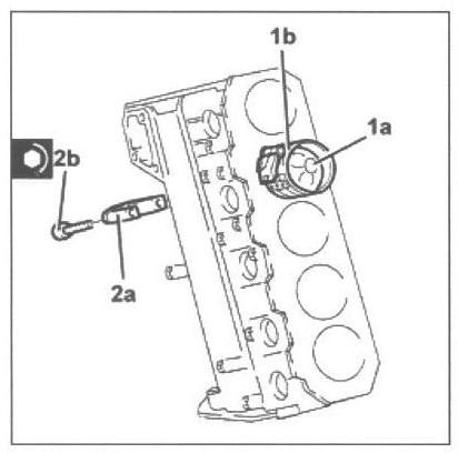
Fit piston-connecting rod assembly (1 a) complete with half-bearing using tool (1b). The piston-connecting rod assemblies are fitted in the cylinder block/crankcase so that the combustion chamber in the piston is facing the intake side. For the selection of the connecting rod half-bearings, follow the procedure described previously for the main journal halfbearings. Fit connecting rod cap (2 a) complete with half-bearing and secure it without tightening bolts (2b). Fit the connecting rods so that the number stamped on each rod faces toward the same side as the number stamped on the big end (inlet side). For the remaining cylinders, carry out the same operations to refit the pistons and connecting rods. Test the crankpin clearance by applying plastigage to measure crankpin installation clearance.
Tighten connecting rod cap bolts to the recommended torque.
Connecting rod big end bearing caps
Bolt M9 (da Nm) 2.4 ÷ 2.6 + 60°

Undo the bolts and remove the connecting rod caps complete with half-bearings. Using an appropriate graduated measuring tool (1 a),measure the clearance indicated by plastigage (1b).
Clearance between crankpins crankshaft bearings
VF4 0.030 ÷ 0.056 mm
VF5 0.016 ÷ 0.070 mm
If the value measured is not within the recommended figures, replace the connecting rod bearings. Carry out this test on all the crankpins, one at a time, without ever turning the crankshaft. Fit the connecting rod caps complete with half bearings and tighten the bolts. Tighten connecting rod cap bolts to the recommended torque.
Connecting rod big end bearing caps
Bolt M9 (da Nm) 2.4 ÷ 2.6 +60°
Remove the flange for rotating the crankshaft. Place the crankcase rear cover with integrated oil seal in position and secure it by tightening the bolts to the recommended torque.
Flywheel side oil seal cover
Bolt (pre-treated to be replaced.) (engine block side) M6 (daNm) 0.8 ÷1.0
Crankshaft oil seal front cover
Bolt (pre-treated to be replaced) (engine block side) M6 (daNm) 0.8 ÷1.0
Refit the engine oil intake duct complete with O-ring in its housing and secure it by tightening the bolts to the specified torque.
Engine oil intake
VF4 Bolt M6 (daNm) 0.8 (oil pump side)
VF5 Bolt M6 (daNm) 0.9 (oil pump side)
Apply silicon sealant to the entire perimeter of the oil sump. Place the oil sump back in its housing. Tighten the bolts securing the oil sump to the crankcase to the recommended torque using the tool (spanner).
Engine oil sump
Bolts front and rear M8 (daNm) 2.5
Engine oil sump
Side bolts M6 (daNm) 0.9
Fit the tool for rotating the crankshaft (flange). Position the timing belt toothed drive pulley in its housing and tighten the bolt (anti-clockwise thread) to the recommended torque.
Toothed drive pulley
Left hand bolt M16 (daNm) 32.3 ÷ 35.7 (crankshaft side)
Measure the piston projection in two places at 180° on the gudgeon pin axis using the tool and take the average of the two values measured for each piston. (dial gauge support).

Select the correct size cylinder head gasket depending on the maximum value out of the averages of the projection for each individual piston.
Cylinder head gasket size with average maximum piston projection
0 opening projection -0.020 ÷ +0.100 mm – thickness 0.82 ÷ 0.05 mm

1 opening projection +0.101 ÷ +0.200 mm – thickness 0.92 ÷ 0.05 mm
2 opening projection +0.201 ÷ +0.295 mm – thickness 1.02 ÷ 0.05 mm
VF5
Place the cylinder head centring bushes on the cylinder block. Fit the cylinder head basket selected. Position the cylinder head on the cylinder block/crankcase.

Follow the order shown in the diagram for each tightening se-

quence.
Camshaft housing
VF4 Bolt M12 (daNm) 6.2 ÷ 6.8 + 4.5+90°+90°+90° (Crankcase side)
The value of 2 daNm in the table above is a tightening value
for all the bolts following the order illustrated in the diagram.
VF4
Camshaft housing
VF5 Bolt M12 (daNm) 2 + 4.5+90°+90°+90° (Crankcase side)
The value of 2 daNm in the table above is a tightening value

for all the bolts following the order illustrated in the diagram.
Position the rpm sensor in its housing and secure it using the bolt.
Place the timing belt tensioner mount in its housing and secure it using the bolt. Place the timing belt fixed tensioner in its housing and secure it using the bolt. Fit the pressure pump mounting complete with pump and secure it using the bolts. Place the timing belt side guard in its housing and secure it using the bolts.
VF5
Remove plugs (1 a) and fit camshaft timing tools (1b) on the camshaft housing. Check that the tools marked “A” are correctly fitted in the seats on the camshaft.
Remove the timing tool, (templates) camshaft side, and tighten the plug. Fit a new upper cylinder head basket in position. Position the camshaft housing and secure it by tightening the bolts to the recommended torque.

Camshaft housing
Bolt M8 (daNm) 2.3 ÷ 2.8 (cylinder head side
Loosen the bolt fixing the exhaust side timing belt toothed drive pulley. Undo the bolt fixing the crankcase front cover shown in the diagram. Temporarily fit the toothed timing drive belt on the toothed drive pulley.
Fit tool (2 a template) and fasten it using calibrated screw (2b). Fully fit the toothed timing drive belt.
Use a screwdriver for leverage in opening (2 a) until the reference for tensioner (2b) is aligned with reference opening (2c). In this position, tighten nut (2d) for the belt tensioner to the recommended torque.
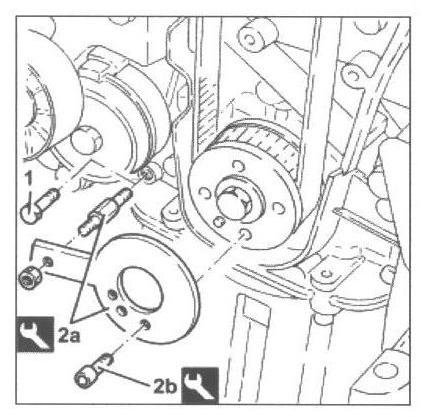
Timing moving tensioner
Nut M8 (daNm) 2.3 ÷ 2.8
Tighten the bolt fixing the exhaust side timing belt toothed drive pulley to the specified torque.

Driver toothed pulley
Bolt M12 (daNm) 2.9 ÷ 3.2 + 40° (camshaft side)
Remove the camshaft timing tools, exhaust and crankshaft side.
Rotate the crankshaft through two turns and check again that the timing is correct by refitting the timing tools removed previously. Check the collimation of the reference marks for the tensioning of the timing belt tensioner and remove the timing tools. Tighten the bolt fixing the crankcase front cover removed previously. Tighten the plug on the upper cylinder head for fitting the exhaust-side timing tool. Fit the injectors and brackets in their seats and tighten the nuts. VF4: Start the assembly with the injector on the fourth cylinder and follow the sequence until the first cylinder. VF5: Start the assembly with the injector on the fifth cylinder and follow the sequence until the first cylinder.
Place the fuel return pipe back in place and connect it to the injectors and the return manifold pipe. Place the single fuel manifold in its housing and secure it by tightening the bolts to the recommended torque.
Single fuel manifold pipe (rail)
Bolt M8 (daNm) 2.3 ÷ 2.8 ( cylinder head extension side )
Connect the return pipe to the single fuel manifold and secure it with the band.
Lace new rigid pipes from the fuel manifold to the injectors in their housing and tighten the connectors to the recommended torque.
Pipes from fuel manifold to injectors
Connector M14 (daNm) 2.2 ÷ 2.4 (rail side)
Connector M12 (daNm) 2.4 ÷ 2.6 (injector side)
Place a new rigid pipe between the pump and the single fuel manifold back in its housing and tighten the connectors to the recommended torque.
Pipes from pressure pump to fuel manifold
Connector M14 (daNm) 2.2 ÷ 2.4 (fuel manifold side)
Connector M12 (daNm) 2.2 ÷ 2.4 (pressure pump side)
Refit the auxiliary drive belt pulley and secure by tightening the bolts to the recommended torque.
Services pulley on crankshaft
Bolt M8 (daNm) 2.3 ÷ 2.5 (crankshaft side)
Refit the timing belt guard and secure it using the bolts.
Place the exhaust manifold assembly, complete with new gasket, back in its housing and secure it by tightening the nuts to the recommended torque.
Exhaust manifold
Nut M8 (daNm) 2.3 ÷ 2.8 (turbocharger side)
Engine oil supply pipe to turbo - crankcase
Connector M10 (daNm) 4.5 ÷ 5.5
Connect the turbocharger lubrication oil outlet pipe to the sump and tighten the bolts to the recommended torque.
Engine oil supply pipe from turbo
Bolt M6 (daNm) 0.8 ÷ 1.0 (engine block side)
Place the alternator in position and secure it by tightening the bolts to the recommended torque.
Alternator
Bolt M12x1.25x120 (daNm) 6.3 ÷ 7.7
Bolt M10x1,25x100 (daNm) 4.5 ÷ 5.5
Engine components single belt moving tensioner
Bolt M8 (daNm) 2.3 ÷ 2.5
Fit and tension the single auxiliary drive belt by working on the automatic tensioner using the tool (spanner).
Secure the electrical connection for the engine oil pressure switch.
Secure the electrical connection for the rpm sensor Attach the electrical connection for the coolant temperature sensor.
Secure the electrical connection for the pressure relief sensor. Secure the electrical connections for the spark plugs. Secure the electrical connection for the pressure regulator on the single fuel manifold. Secure the electrical connections for the injectors. Secure the electrical connection for the timing sensor. Secure the electrical connection for the alternator.
Place the alternator power supply cable back in its housing and secure it using the nut. Secure the engine wiring using the various retaining clips.