23 minute read
Chapter 3 Machine Disassembly and Replacement


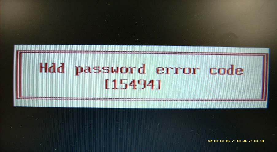
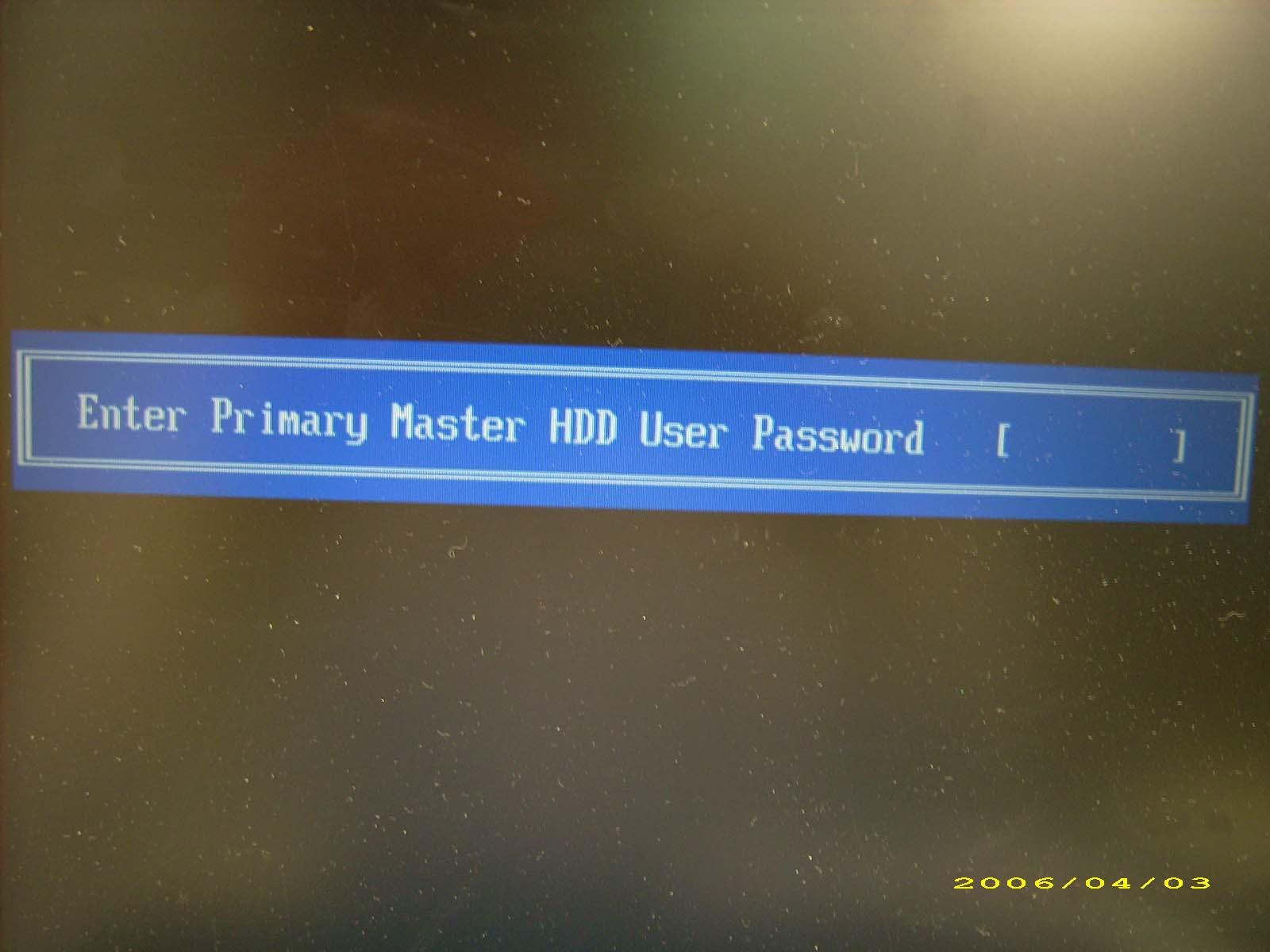
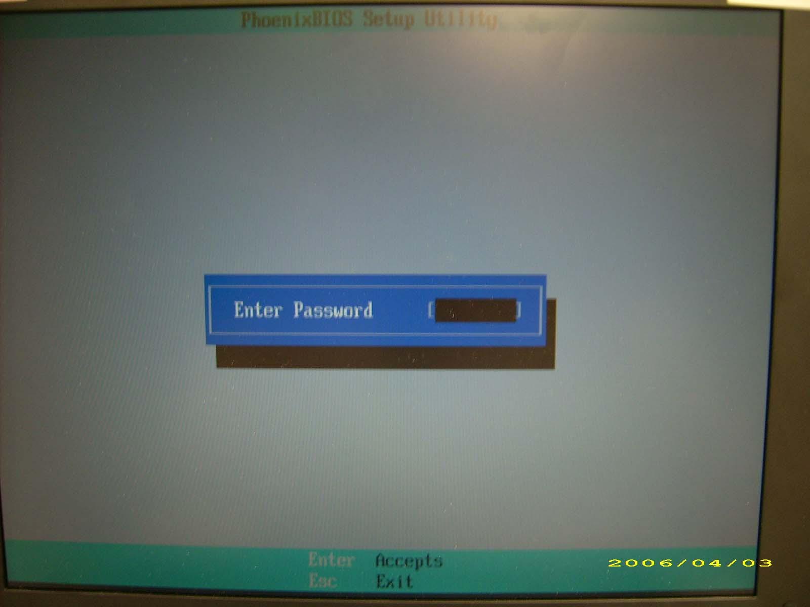
This section provide you with removing HDD/BIOS method: Remove HDD Password: q If you key in wrong HDD password for three time, “HDD password error code” would display on the screen. See the image below.
q If you need to solve HDD password locked problem, you can run HDD_PW.EXE
1. Key in “hdd_pw 15494 0” 2. Select “2” 3. Choose one upper-case string
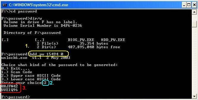
q Reboot system and key in “0KJFN42” or “UVEIQ96” to HDD user password.
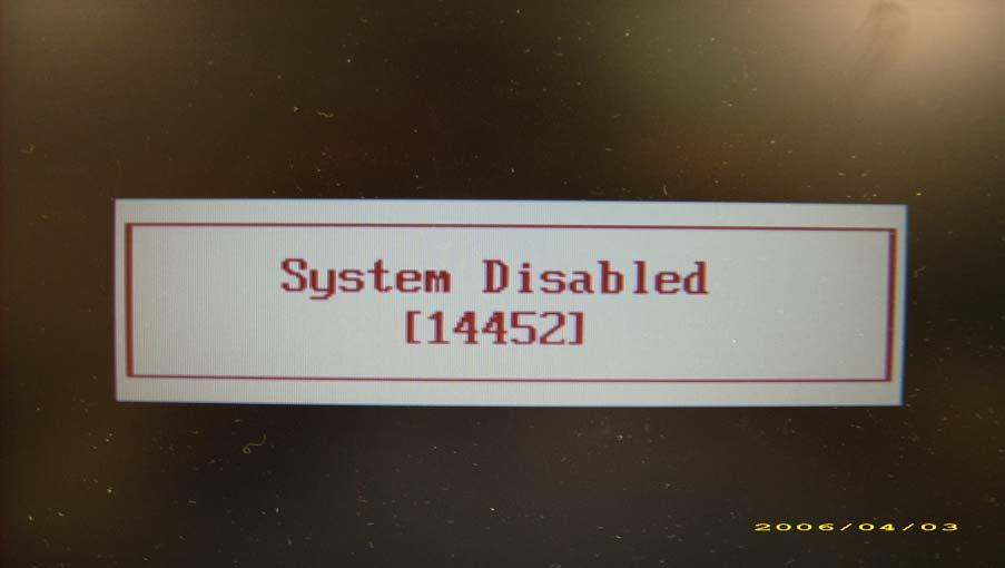
Remove BIOS Password: q If you key in wrong Supervisor Password for three time, “System Disabled” would display on the screen. See the image below.
q If you need to solve BIOS password locked problem, you can run BIOS_PW.EXE
1. Key in “bios_pw 14452 0” 2. Choose one upper-case string
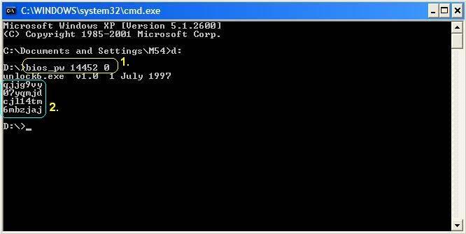
q Reboot the system and key in “qjjg9vy” or “07yqmjd” to BIOS user password.
Machine Disassembly and Replacement
This chapter contains step-by-step procedures on how to disassemble the notebook computer for maintenance and troubleshooting.
Disassembly Requirements
To disassemble the computer, you need the following tools: • Wrist grounding strap and conductive mat for preventing electrostatic discharge • Flat screwdriver • Philips screwdriver • Hex screwdriver • Plastic flat screwdriver • Plastic tweezers NOTE: The screws for the different components vary in size. During the disassembly process, group the screws with the corresponding components to avoid mismatch when putting back the components.
Pre-disassembly Instructions
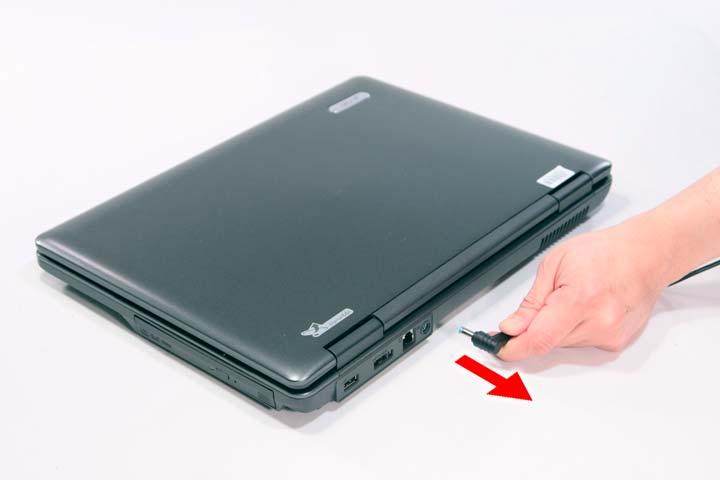
Before proceeding with the disassembly procedure, make sure that you do the following: 1. Turn off the power to the system and all peripherals. 2. Unplug the AC adapter and all power and signal cables from the system.
3. Place the system on a flat, stable surface. 4. Remove the battery pack.
Disassembly Process
The disassembly process is divided into the following stages: • External module disassembly • Main unit disassembly • LCD module disassembly The flowcharts provided in the succeeding disassembly sections illustrate the entire disassembly sequence. Observe the order of the sequence to avoid damage to any of the hardware components. For example, if you want to remove the main board, you must first remove the keyboard, then disassemble the inside assembly frame in that order. Main Screw List
Item Screw Color Part No.
A M2 x L3 Black 86.9A552.3R0
B M2 x L4 Silver 86.9A552.4R0
C M2.5 x L5 Black 86.00E33.736
D M2 x L8 Black 86.00E34.738
E M3 x L4 Silver 86.9A554.4R0
F M2 x L3 Silver 86.00E13.524
G M2.5 x L5 Black 86.00F87.735
H M2 x L3 Silver 86.00C07.220
External Modules Disassembly Flowchart
The flowchart below gives you a graphic representation on the entire disassembly sequence and instructs you on the components that need to be removed during servicing. For example, if you want to remove the main board, you must first remove the keyboard, then disassemble the inside assembly frame in that order. EXTERNAL MODULE DISASSEMBLY
TURN OFF POWER AND PERIPHERALS
UNPLUG POWER CABLES
REMOVEBATTERY PACK
SDDUMMY CARD CaptiveScrewx6
SDDUMMY CARD LOWER COVER ExpressCard DUMMYCARD
Bx2
WLAN BOARD
DIMM MODULES Cx1
ODD MODULE
OPTICALDISK DRIVE Ax1 OPTICAL LOCKER BRACKET Bx1
HDD MODULE
Ex2
HARD DISK BRACKET HARD DISK DRIVE
Screw List
Item Screw Color Part No.
A M2 x L3 Silver 86.9A552.3R0
B M2 x L4 Silver 86.9A552.4R0
C M2.5 x L5 Black 86.00E33.736
E M3 x L4 Silver 86.9A554.4R0
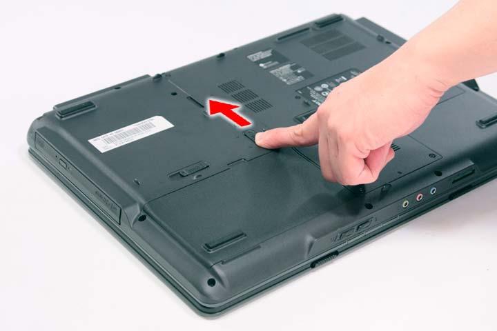
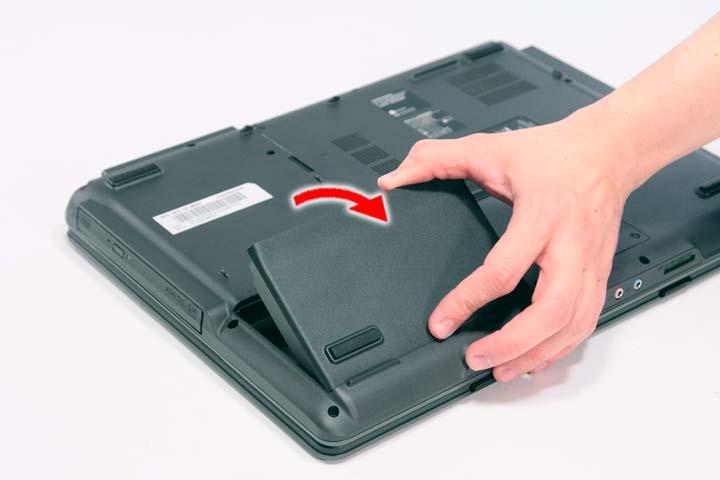
1. Turn base unit over. 2. Slide the battery lock/unlock latch to the unlock position.
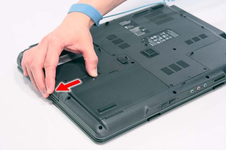
3. Slide and hold the battery release latch to the release position.
4. Then remove the battery from the main unit.
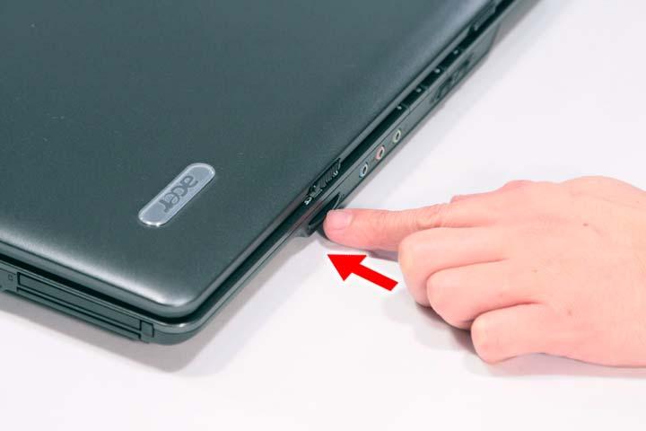
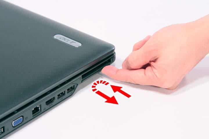
1. Push the SD dummy card all the way in to eject it.
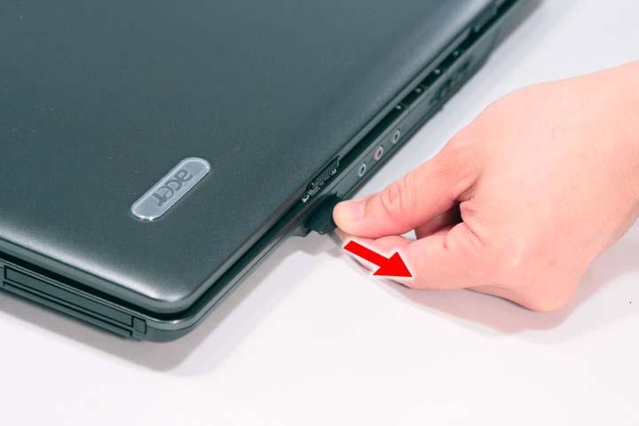
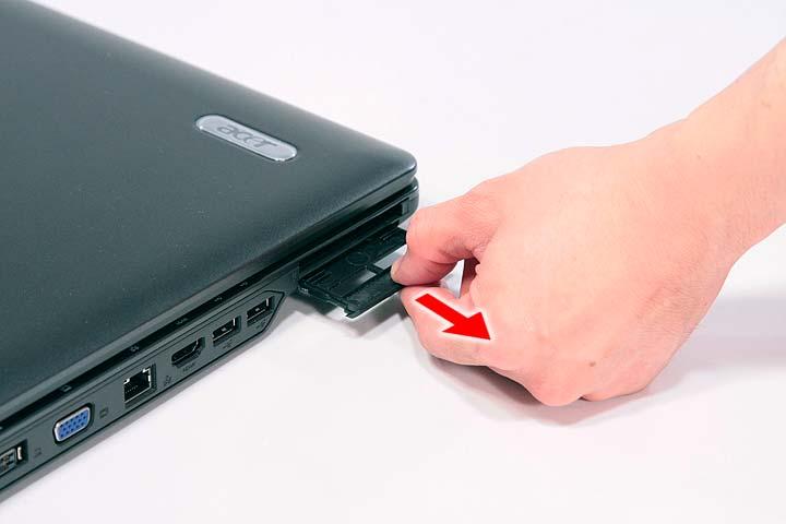
2. Pull it out from the slot.
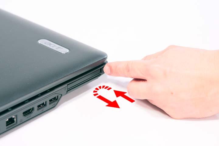
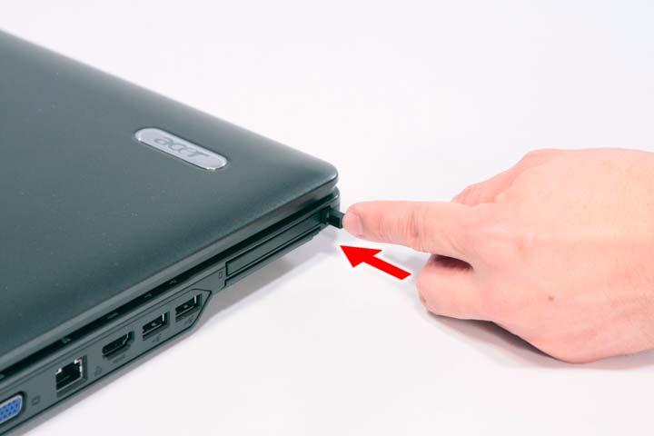
1. Press the eject button to pop out the button.
2. Press it again to pop out the PC dummy card.
3. Remove the PC dummy card from the slot.
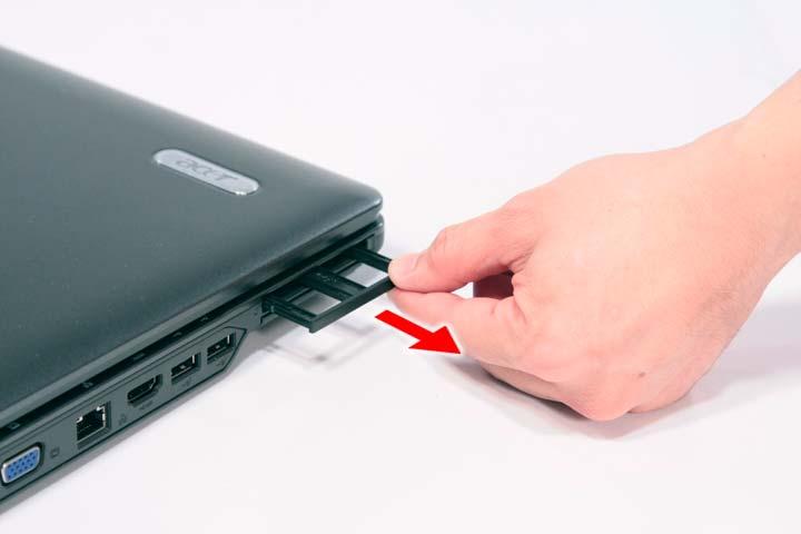
5. Pull it out from the slot.
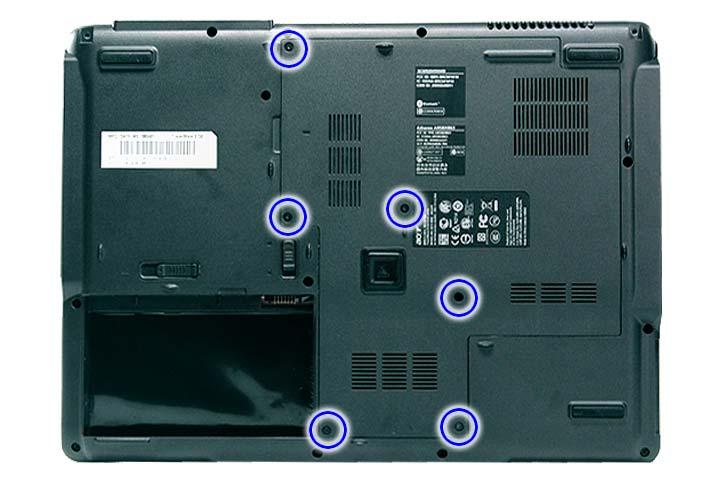
Removing the Lower Cover
1. See “Removing the Battery Pack” on page 54. 2. Remove the six captive screws securing the lower cover.
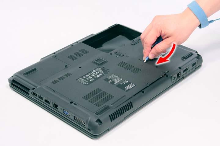
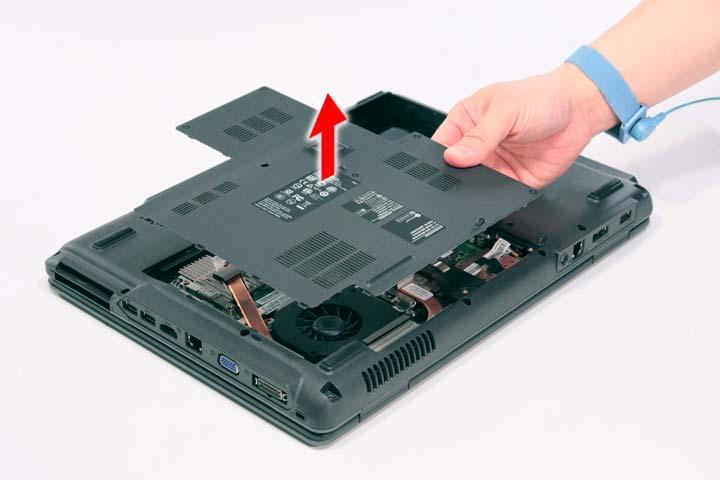
4. Remove the lower cover from the lower case.
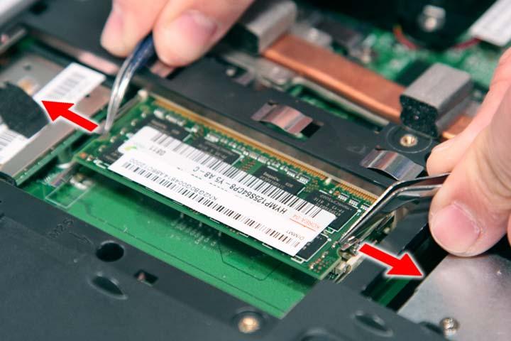
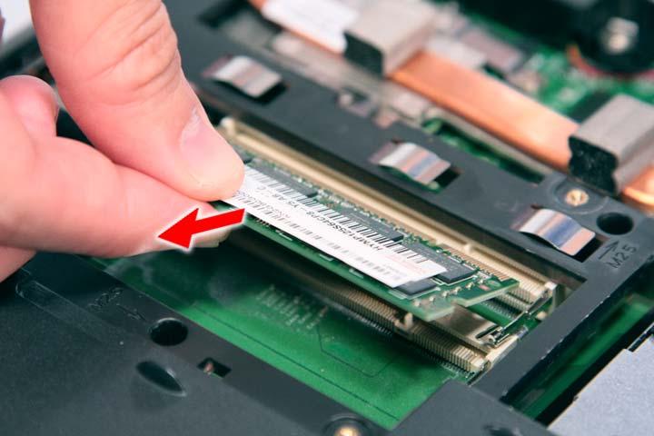
Removing the DIMM
1. See “Removing the Battery Pack” on page 54. 2. See “Removing the Lower Cover” on page 57.. 3. Push out the latches on both sides of the DIMM socket to release the DIMM.
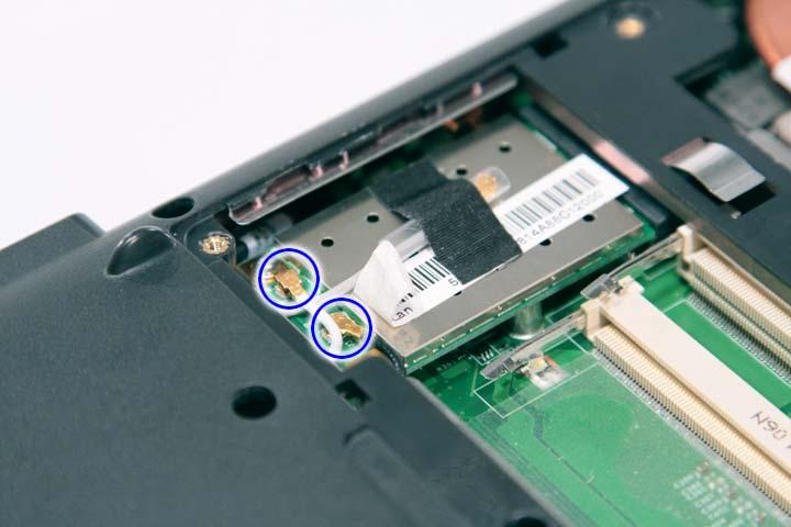
Removing the WLAN Board Modules
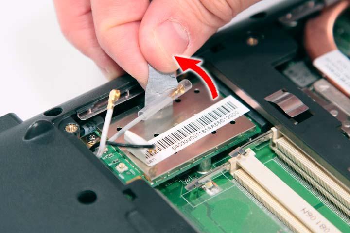
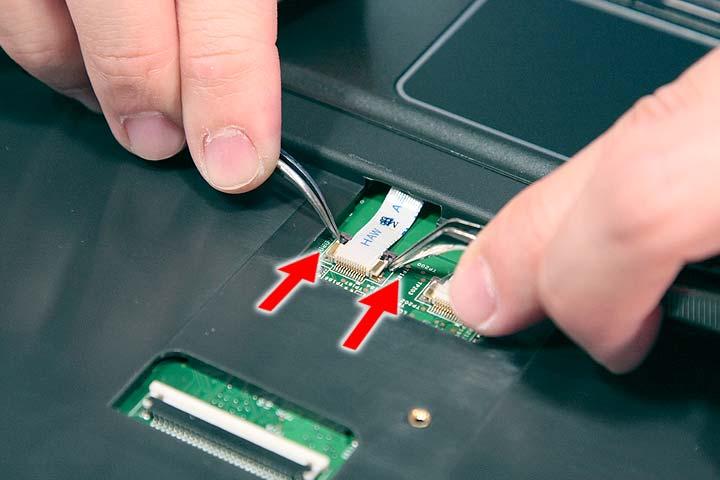
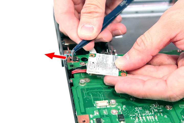
1. See “Removing the Battery Pack” on page 54. 2. See “Removing the Lower Cover” on page 57. 3. Disconnect the antenna cables from the WLAN board.
NOTE: There are 2 antenna cables connected to the WLAN board. The Black antenna cable is connected to MAIN connector and the White antenna cable is connected to AUX connector.
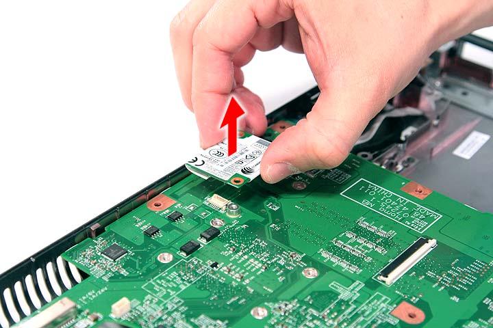
5. Remove the two screws (B) on the WLAN board to release the WLAN board.
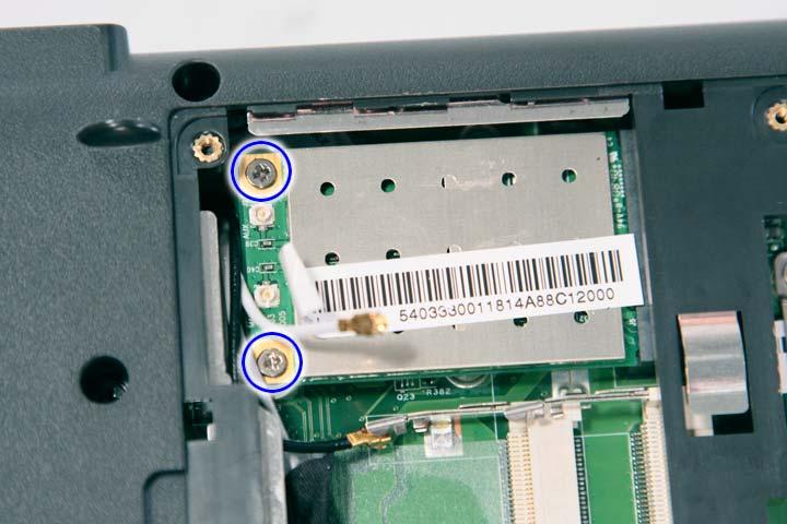
Step Size (Quantity) Color Torque 1~2 M2 x L4 (2) Silver 1.6 kgf-cm
6. Detach the WLAN board from the WLAN socket.
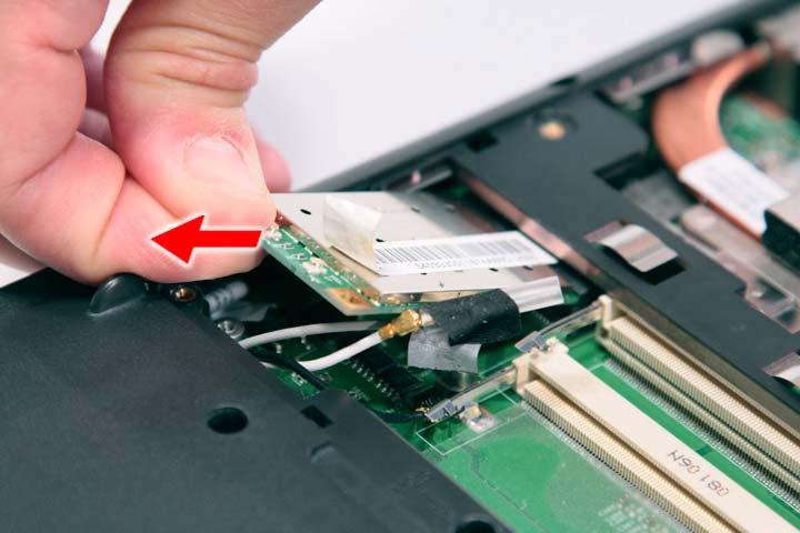
NOTE: When attaching the antenna back to the WLAN board, make sure the cable are arranged properly.
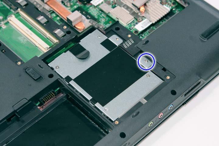
1. See “Removing the Battery Pack” on page 54. 2. See “Removing the Lower Cover” on page 57. 3. Remove the one screw (B) securing the hard disk drive module.
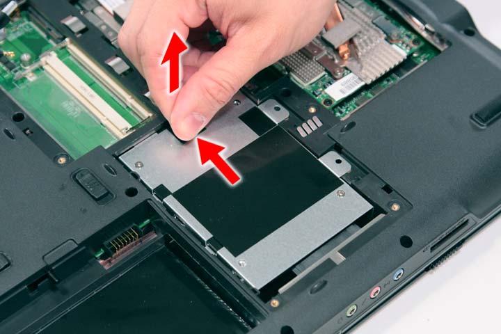
4. Using the plastic tab, slide the hard disk drive module away from the connector; lift up the hard disk module to remove from the bay.
NOTE: To prevent damage to device, avoid pressing down on it or placing heavy objects on top of it.
Step Size (Quantity) Color Torque 1 M2 x L4 (1) Silver 1.6 kgf-cm
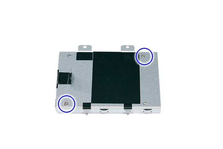

Step Size (Quantity) Color Torque 1~2 M3 x L4 (2) Silver 3.0 kgf-cm
Removing the Optical Drive Module
1. See “Removing the Battery Pack” on page 54. 2. See “Removing the Lower Cover” on page 57.
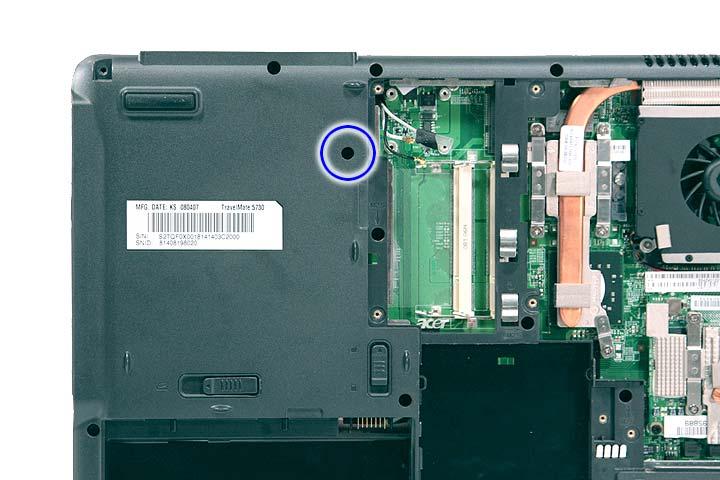
Step Size (Quantity) Color Torque 1 M2.5 x L6 (1) Black 3.0 kgf-cm
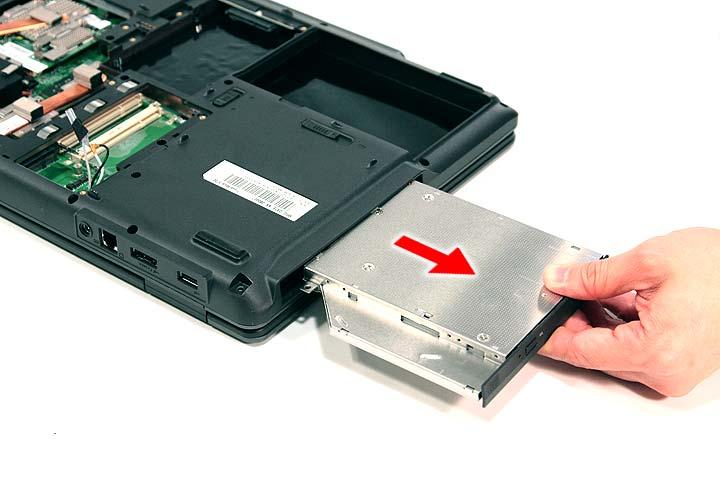
4. Use a screw driver to carefully push the odd drive tray out as shown.
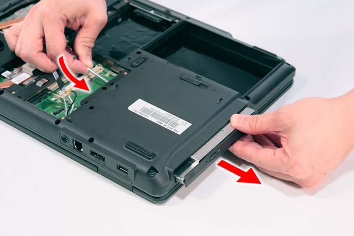
5. Slowly pull out the odd module from the odd drive bay.
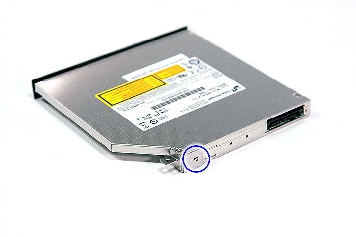
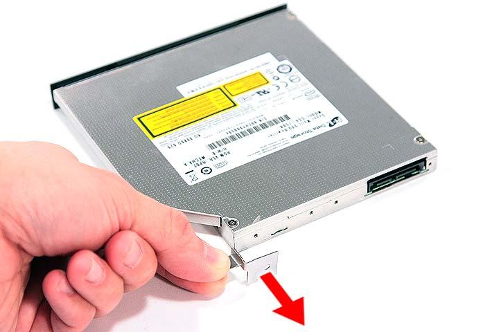
Step Size (Quantity) Color Torque 1 M2 x L3 (1) Silver 1.6 kgf-cm
Main Unit Disassembly Flowchart
MAIN UNIT DISASSEMBLY
Ax1
POWER BOARD MAIN UNIT
MIDDLECOVER
Ax2
KEYBOARD
Bx2,Dx2
LCD MODULE
Cx14
UPPER CASE Bx2
HEATSINKFAN
SCREWX5(CPU)
SCREWX4(VGA) CPU/VGA THERMALMODULE
CPU Bx2
VGACARD
Hx2
SPEAKER MODULE Bx2 MODEM BOARD MODULE Bx1
USB BOARD MODULE
Bx3
MAIN BOARD Ax1
LAUNCH BOARD Fx2,Ax1
TOUCHPAD BRACKET
TOUCHPAD MODULE FINGERPRINT MODULE
Screw List
Item Screw Color Part No.
A M2 x L3 Silver 86.9A552.3R0
B M2 x L4 Silver 86.9A552.4R0
C M2.5 x L5 Black 86.00E33.736
D M2 x L8 Black 86.00E34.738
F M2 x L3 Silver 86.00E13.524
H M2 x L3 Silver 86.00C07.220
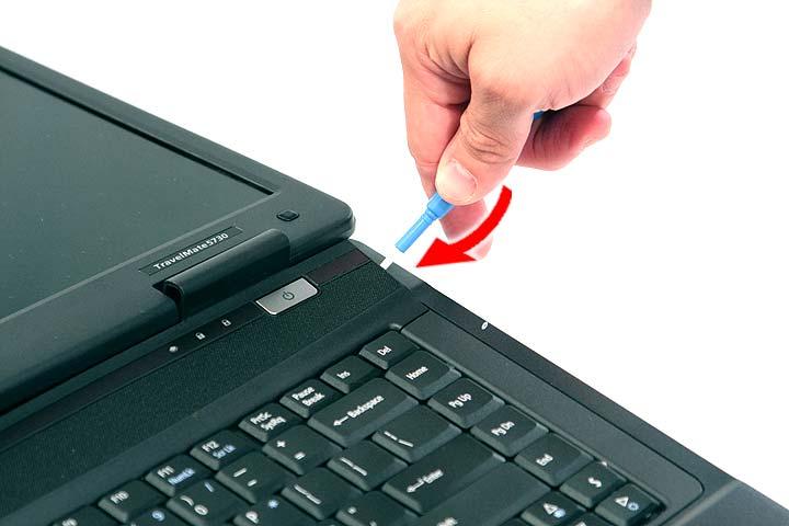
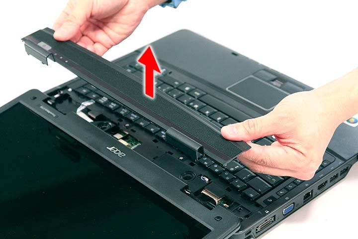
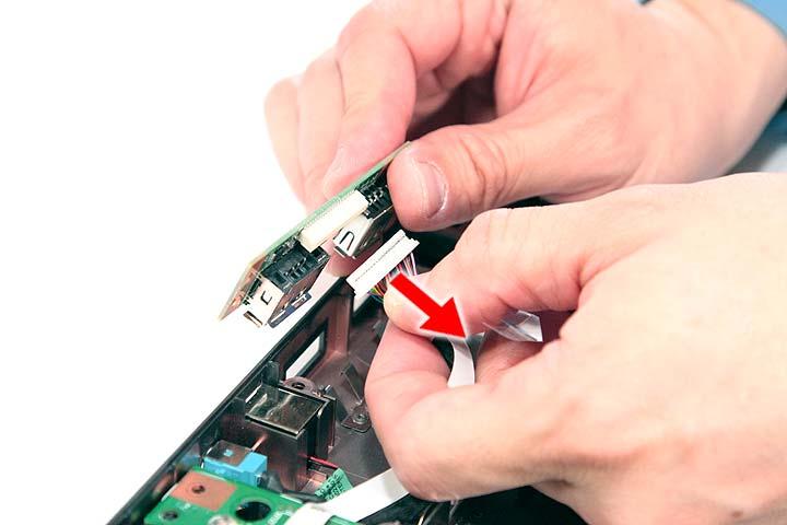
1. See “Removing the Battery Pack” on page 54. 2. Use a plastic screw driver to pry loose the side of the middle cover.
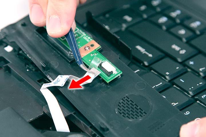
3. Carefully pry loose the middle cover from the latches securing it and turn it over on the keyboard to gain access to the cable connected to the power board.
4. Disconnect the cable connected to the power board and remove the middle cover from the system.
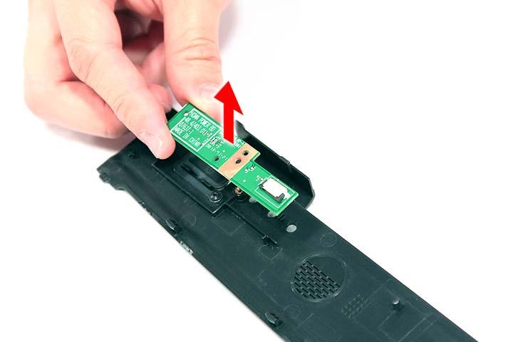
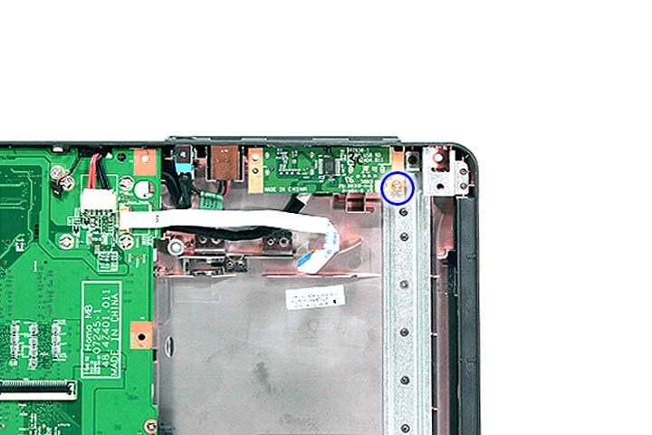
Removing the Power Board
1. See “Removing the Battery Pack” on page 54. 2. See “Removing the Middle Cover” on page 66.
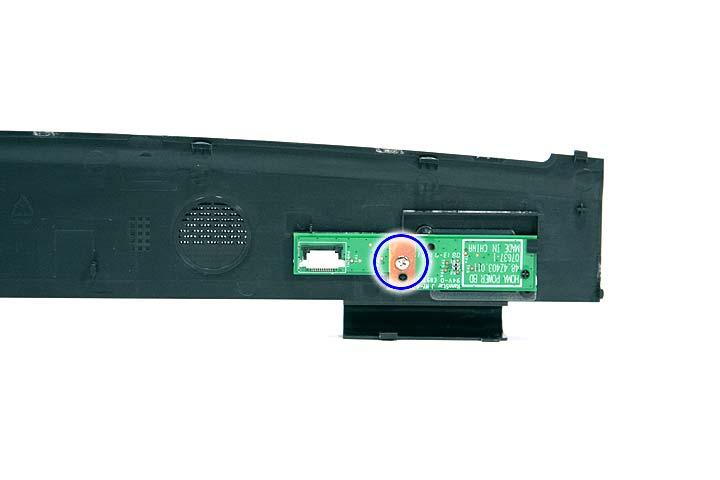
Step Size (Quantity) Color Torque 1 M2 x L3 (1) Silver 1.6 kgf-cm
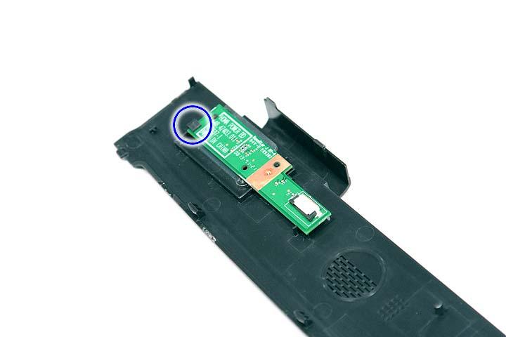
4. Release the power board from the latches and remove it from the middle cover.
1. See “Removing the Battery Pack” on page 54. 2. See “Removing the Middle Cover” on page 66. 3. Remove the two screws (A) securing the keyboard.
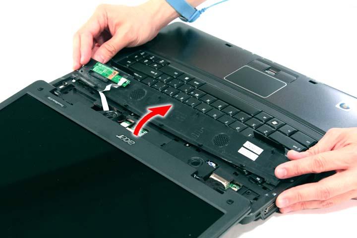
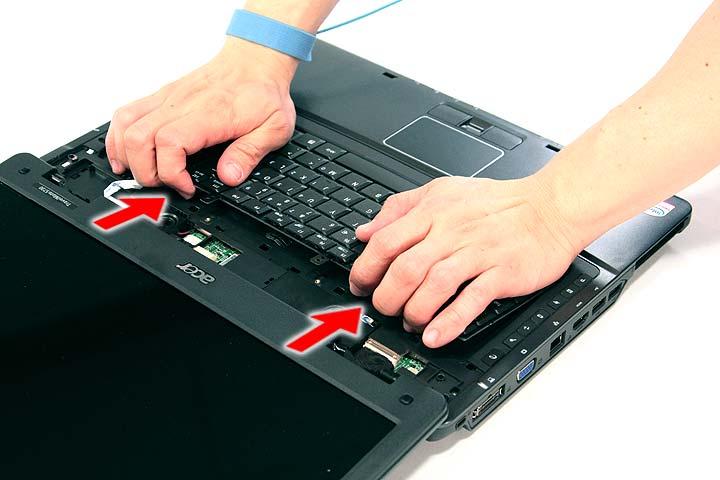
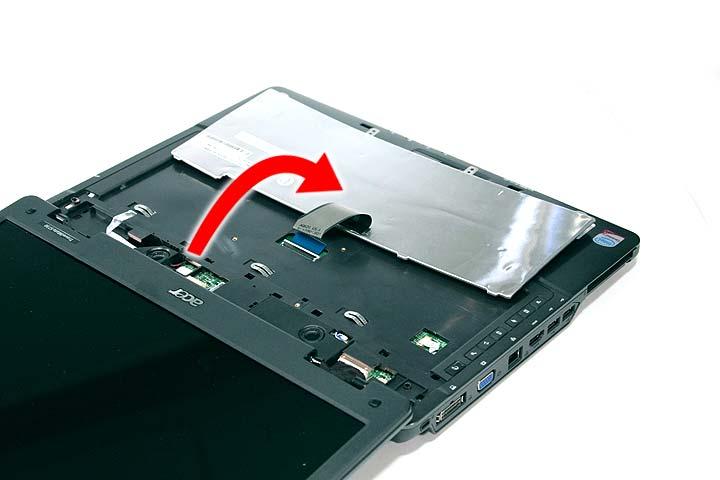
4. Carefully pry loose the keyboard and turn it over on the touchpad area.
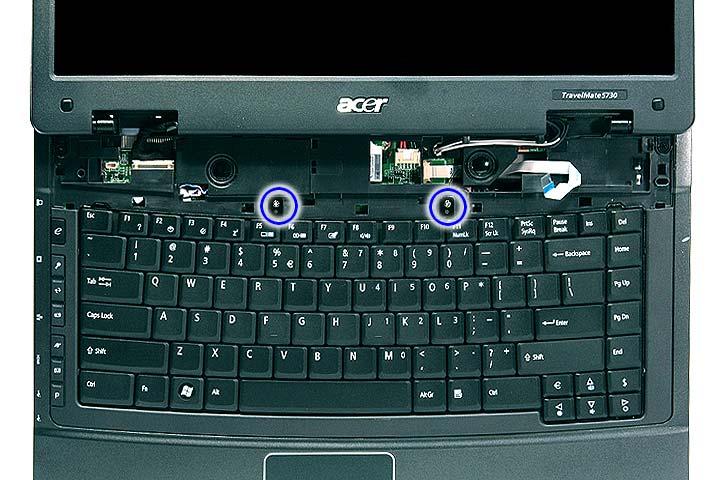
Step Size (Quantity) Color Torque 1~2 M2 x L3 (2) Silver 1.6 kgf-cm
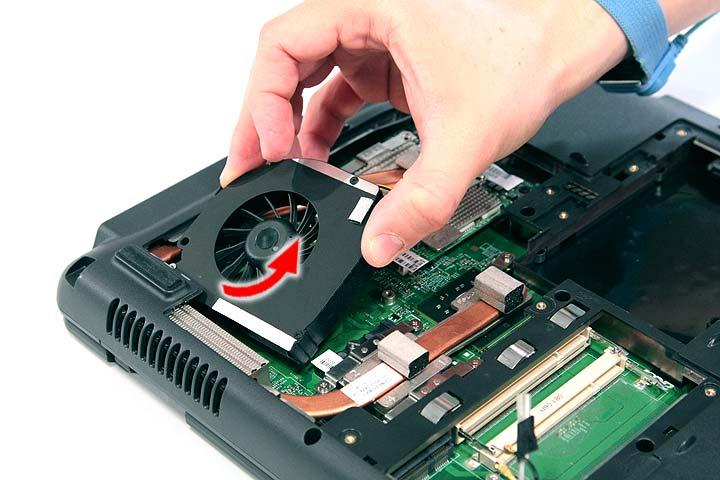
Removing the Heatsink Fan Module
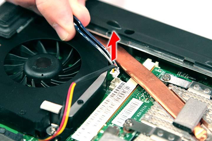
1. See “Removing the Battery Pack” on page 54. 2. See “Removing the Lower Cover” on page 57. 3. Disconnect the heat sink fan connector from the main board.
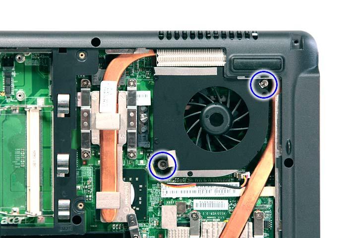
Step Size (Quantity) Color Torque 1~2 M2 x L4 (2) Silver 1.6 kgf-cm
5. Carefully lift up the heatsink fan module.
Removing the CPU and VGA Heatsink Module
1. See “Removing the Battery Pack” on page 54. 2. See “Removing the Lower Cover” on page 57. 3. See “Removing the Heatsink Fan Module” on page 70.
4. Remove the four screws securing the VGA board heatsink module (Discrete Model only) and the five screw securing the CPU heatsink module.
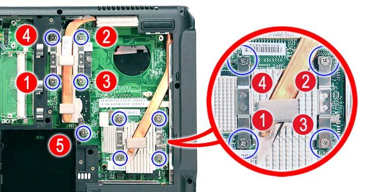
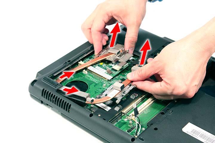
5. Carefully remove the heatsink module from the system.
Removing the CPU
1. See “Removing the Battery Pack” on page 54. 2. See “Removing the Lower Cover” on page 57. 3. See “Removing the Heatsink Fan Module” on page 70. 4. See “Removing the CPU and VGA Heatsink Module” on page 71.
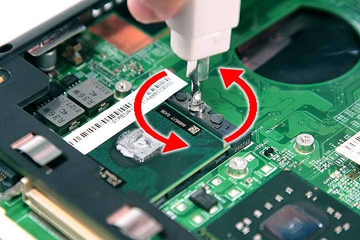
6. Lift up carefully to remove the CPU.
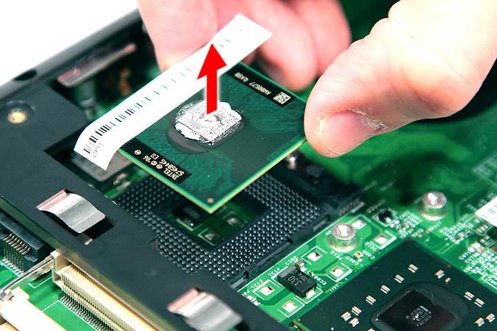
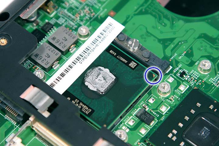
NOTE: When installing the CPU, make sure to install the CPU with PIN 1 at the corner as shown.
Removing the VGA Board (Discrete Model only)
1. See “Removing the Battery Pack” on page 54. 2. See “Removing the Lower Cover” on page 57.
3. See “Removing the Heatsink Fan Module” on page 70. 4. See “Removing the CPU and VGA Heatsink Module” on page 71. 5. Remove the two screws (B) securing the VGA board to the main board.
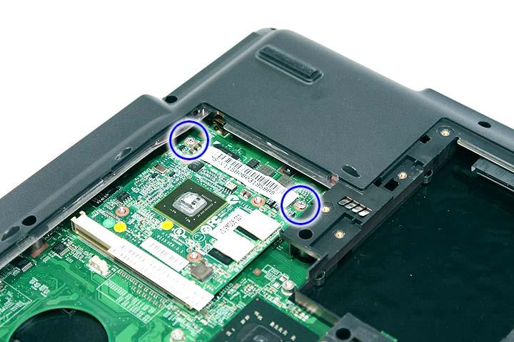
Step Size (Quantity) Color Torque 1~2 M2 x L4 (2) Silver 1.6 kgf-cm
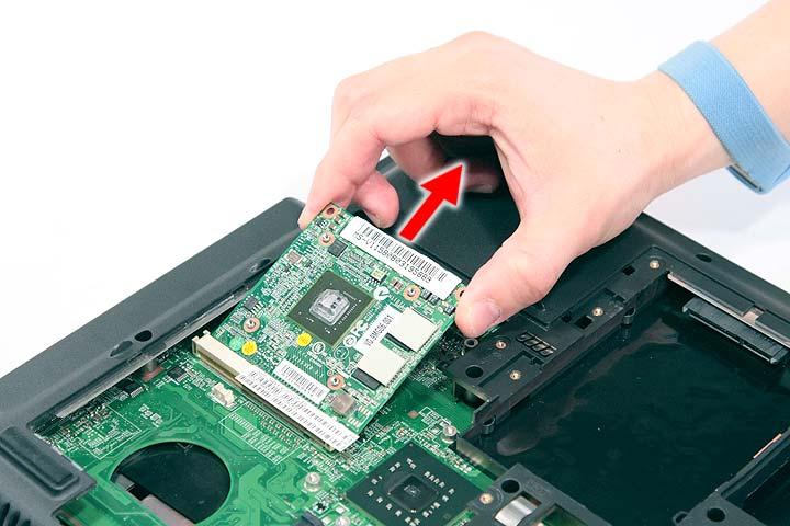
6. Remove the VGA board from the main board.
Removing the LCD Module
1. See “Removing the Battery Pack” on page 54. 2. See “Removing the SD dummy card” on page 55. 3. See “Removing the PC and ExpressCard dummy cards” on page 56. 4. See “Removing the Lower Cover” on page 57. 5. See “Removing the WLAN Board Modules” on page 59. 6. See “Removing the Middle Cover” on page 66. 7. See “Removing the Keyboard” on page 69.
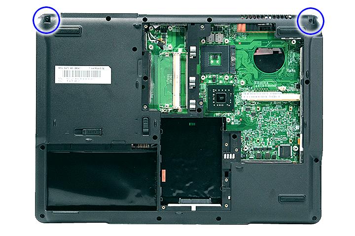
Step Size (Quantity) Color Torque 1~2 M2.5 x L6 (2) Black 3.0 kgf-cm
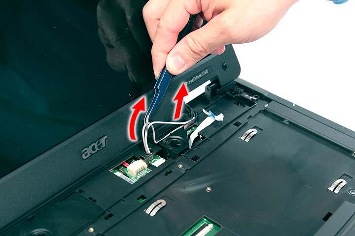
9. Carefully pull out the wireless antenna cables from the hole and release the cables from the latches.
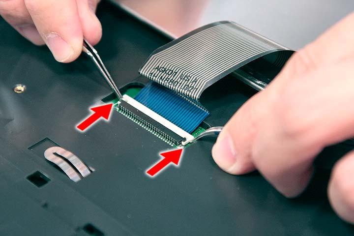
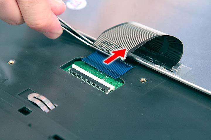
10. Disconnect the LCD cable connector from the main board.
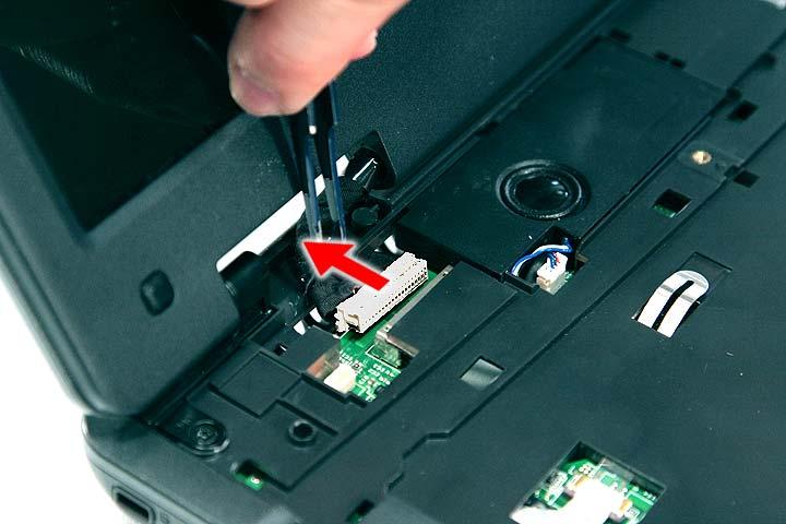
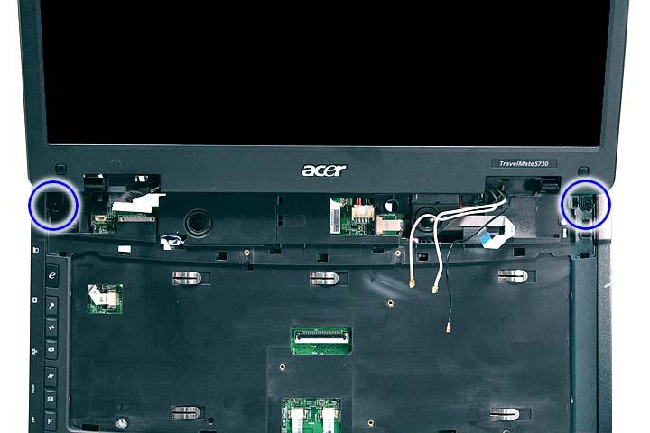
Step Size (Quantity) Color Torque 1~2 M2 x L8 (2) Black 4.0 kgf-cm
12. Carefully remove the LCD module from the base unit.
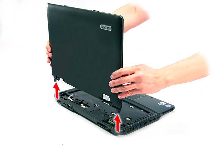
NOTE: When connecting the cable back to the unit, please note that the cable should be routed well.
Separating the Upper Case from the Lower Case
1. See “Removing the Battery Pack” on page 54. 2. See “Removing the SD dummy card” on page 55. 3. See “Removing the PC and ExpressCard dummy cards” on page 56. 4. See “Removing the Lower Cover” on page 57. 5. See “Removing the DIMM” on page 58. 6. See “Removing the WLAN Board Modules” on page 59. 7. See “Removing the Hard Disk Drive Module” on page 61. 8. See “Removing the Optical Drive Module” on page 62. 9. See “Removing the Middle Cover” on page 66. 10. See “Removing the Keyboard” on page 69. 11. See “Removing the Heatsink Fan Module” on page 70. 12. See “Removing the CPU and VGA Heatsink Module” on page 71.
13. See “Removing the CPU” on page 72. 14. See “Removing the VGA Board (Discrete Model only)” on page 73. 15. See “Removing the LCD Module” on page 74. 16. Disconnect the touchpad cable from the TPAD1 connector on the main board.
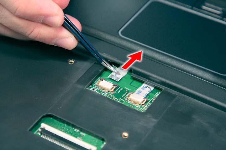
17. Disconnect the fingerprint cable from the FPCN1 connector on the main board.
18. Disconnect the launch board cable from the SWITCHCN1 connector on the main board.
20. Remove the fourteen screws (14 x C) from the bottom panel.
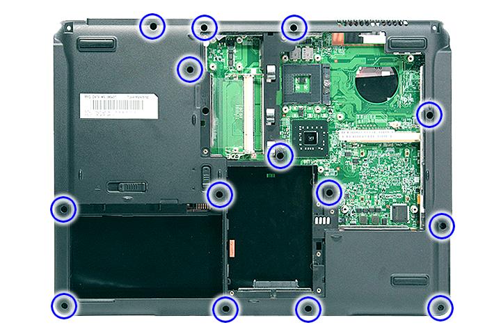
Step Size (Quantity) Color Torque 1~14 M2.5 x L5 (14) Black 2.5 kgf-cm
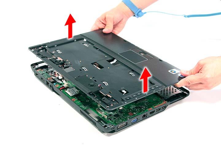
21. Turn the unit over and gently remove the upper case from the lower case.
1. See “Removing the Battery Pack” on page 54. 2. See “Removing the SD dummy card” on page 55. 3. See “Removing the PC and ExpressCard dummy cards” on page 56. 4. See “Removing the Lower Cover” on page 57. 5. See “Removing the DIMM” on page 58. 6. See “Removing the WLAN Board Modules” on page 59. 7. See “Removing the Hard Disk Drive Module” on page 61. 8. See “Removing the Optical Drive Module” on page 62. 9. See “Removing the Middle Cover” on page 66. 10. See “Removing the Keyboard” on page 69. 11. See “Removing the Heatsink Fan Module” on page 70. 12. See “Removing the CPU and VGA Heatsink Module” on page 71. 13. See “Removing the CPU” on page 72. 14. See “Removing the VGA Board (Discrete Model only)” on page 73. 15. See “Removing the LCD Module” on page 74. 16. See “Separating the Upper Case from the Lower Case” on page 76. 17. Remove the two screws (2 x H) securing the left and right speaker modules.
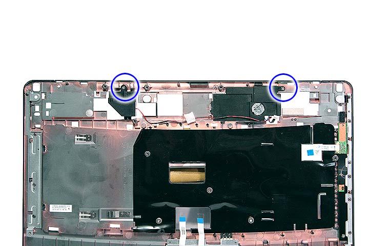
Step Size (Quantity) Color Torque 1~2 M2 x L3 (2) Silver 1.6 kgf-cm
Removing the Launch Board
1. See “Removing the Battery Pack” on page 54. 2. See “Removing the SD dummy card” on page 55. 3. See “Removing the PC and ExpressCard dummy cards” on page 56. 4. See “Removing the Lower Cover” on page 57. 5. See “Removing the DIMM” on page 58. 6. See “Removing the WLAN Board Modules” on page 59. 7. See “Removing the Hard Disk Drive Module” on page 61. 8. See “Removing the Optical Drive Module” on page 62. 9. See “Removing the Middle Cover” on page 66. 10. See “Removing the Keyboard” on page 69. 11. See “Removing the Heatsink Fan Module” on page 70. 12. See “Removing the CPU and VGA Heatsink Module” on page 71. 13. See “Removing the CPU” on page 72. 14. See “Removing the VGA Board (Discrete Model only)” on page 73. 15. See “Removing the LCD Module” on page 74. 16. See “Separating the Upper Case from the Lower Case” on page 76.
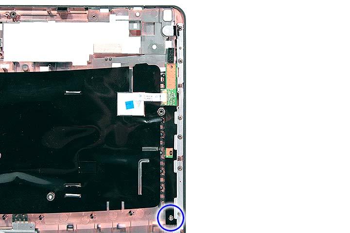
Step Size (Quantity) Color Torque 1 M2 x L3 (1) Silver 1.6 kgf-cm
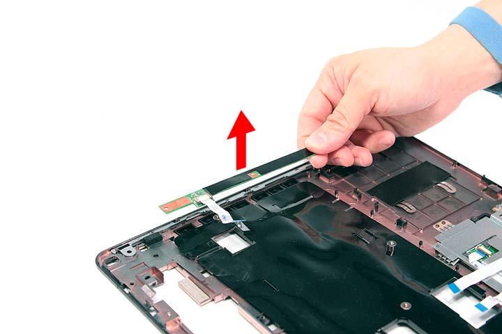
18. Remove the launch board module from the upper case.
Removing the Fingerprint and Touchpad Module
1. See “Removing the Battery Pack” on page 54. 2. See “Removing the SD dummy card” on page 55. 3. See “Removing the PC and ExpressCard dummy cards” on page 56. 4. See “Removing the Lower Cover” on page 57. 5. See “Removing the DIMM” on page 58. 6. See “Removing the WLAN Board Modules” on page 59. 7. See “Removing the Hard Disk Drive Module” on page 61. 8. See “Removing the Optical Drive Module” on page 62. 9. See “Removing the Middle Cover” on page 66. 10. See “Removing the Keyboard” on page 69. 11. See “Removing the Heatsink Fan Module” on page 70. 12. See “Removing the CPU and VGA Heatsink Module” on page 71. 13. See “Removing the CPU” on page 72.
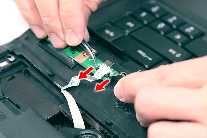
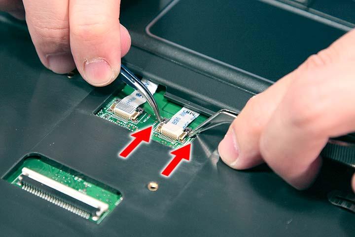
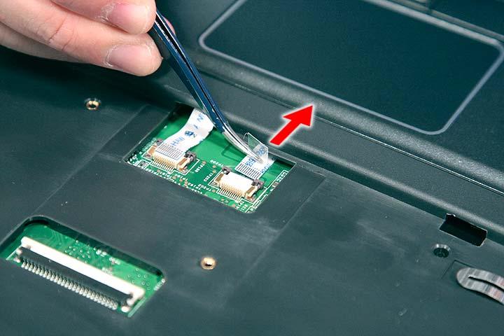
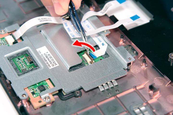
14. See “Removing the VGA Board (Discrete Model only)” on page 73. 15. See “Removing the LCD Module” on page 74. 16. See “Separating the Upper Case from the Lower Case” on page 76. 17. Disconnect the touchpad cable from the touchpad board.
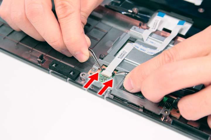
18. Disconnect the fingerprint cable from the fingerprint board.

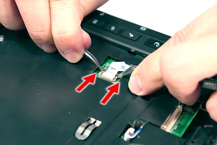
19. Remove the three screws (2 x F, 1 x A) securing the bracket to the upper case.
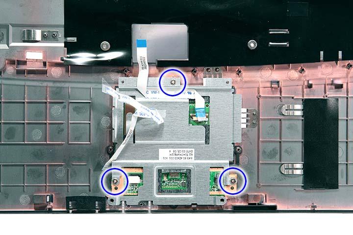
Step Size (Quantity) Color Torque 1~2 M2 x L3 (2) Silver 1.6 kgf-cm 3 M2 x L3 (2) Silver 1.6 kgf-cm
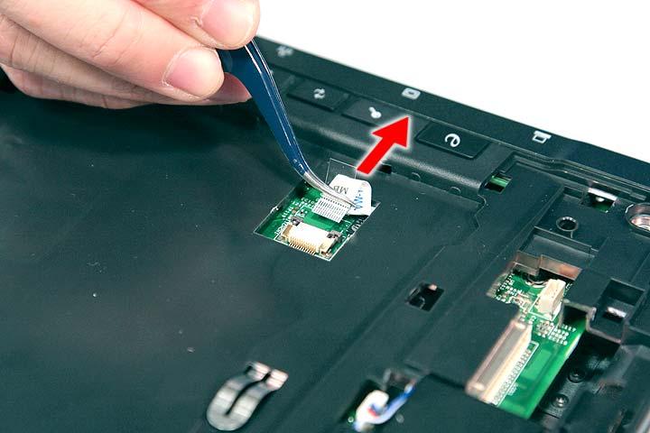
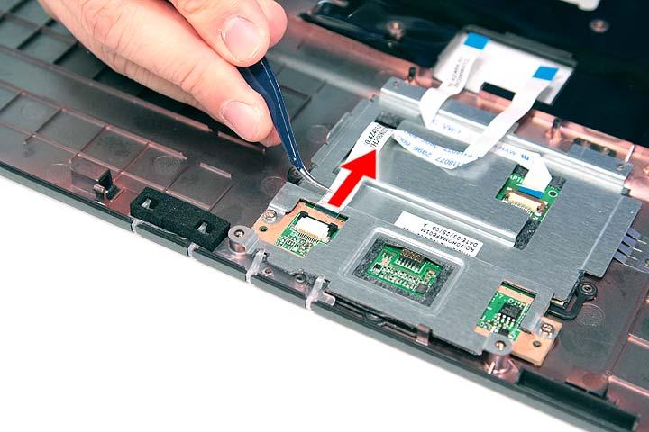
20. Remove the touchpad bracket.
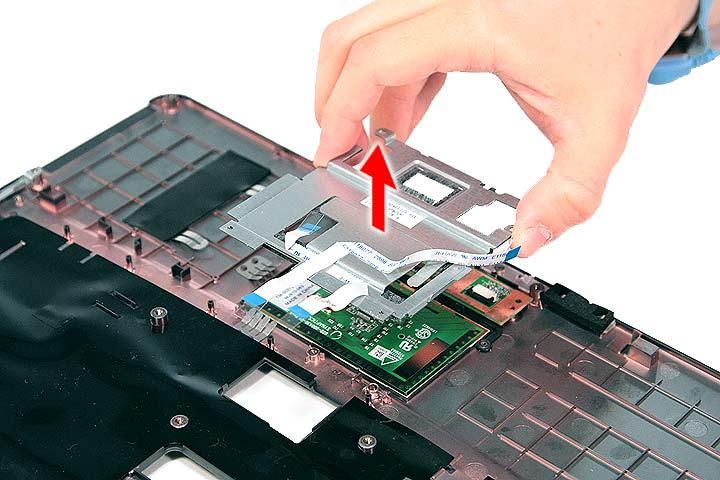
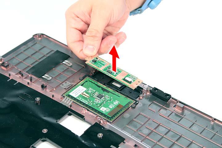
22. Carefully pry loose and remove the touch pad board.
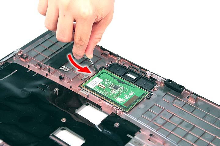
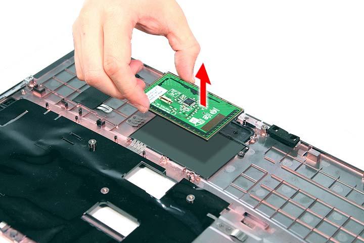
WARNING:The touchpad board is glued to the upper case, only remove the touchpad board if it is defective.
Removing the Modem Board
1. See “Removing the Battery Pack” on page 54. 2. See “Removing the SD dummy card” on page 55.
3. See “Removing the PC and ExpressCard dummy cards” on page 56. 4. See “Removing the Lower Cover” on page 57. 5. See “Removing the DIMM” on page 58. 6. See “Removing the WLAN Board Modules” on page 59. 7. See “Removing the Hard Disk Drive Module” on page 61. 8. See “Removing the Optical Drive Module” on page 62. 9. See “Removing the Middle Cover” on page 66. 10. See “Removing the Keyboard” on page 69. 11. See “Removing the Heatsink Fan Module” on page 70. 12. See “Removing the CPU and VGA Heatsink Module” on page 71. 13. See “Removing the CPU” on page 72. 14. See “Removing the VGA Board (Discrete Model only)” on page 73. 15. See “Removing the LCD Module” on page 74. 16. See “Separating the Upper Case from the Lower Case” on page 76. 17. Remove the two screws (B) securing the modem card.
Step Size (Quantity) Color Torque 1~2 M2 x L4 (2) Silver 1.6 kgf-cm
18. Lift the modem board from the system.
Removing the USB Board Module
1. See “Removing the Battery Pack” on page 54. 2. See “Removing the SD dummy card” on page 55. 3. See “Removing the PC and ExpressCard dummy cards” on page 56. 4. See “Removing the Lower Cover” on page 57. 5. See “Removing the DIMM” on page 58. 6. See “Removing the WLAN Board Modules” on page 59. 7. See “Removing the Hard Disk Drive Module” on page 61. 8. See “Removing the Optical Drive Module” on page 62. 9. See “Removing the Middle Cover” on page 66. 10. See “Removing the Keyboard” on page 69. 11. See “Removing the Heatsink Fan Module” on page 70. 12. See “Removing the CPU and VGA Heatsink Module” on page 71. 13. See “Removing the CPU” on page 72. 14. See “Removing the VGA Board (Discrete Model only)” on page 73. 15. See “Removing the LCD Module” on page 74. 16. See “Separating the Upper Case from the Lower Case” on page 76.
Step Size (Quantity) Color Torque 1 M2 x L4 (1) Silver 1.6 kgf-cm
18. Lift the USB board and disconnect the cable from USBCN1 on the USB board.
Removing the Main Board
1. See “Removing the Battery Pack” on page 54. 2. See “Removing the SD dummy card” on page 55. 3. See “Removing the PC and ExpressCard dummy cards” on page 56. 4. See “Removing the Lower Cover” on page 57. 5. See “Removing the DIMM” on page 58. 6. See “Removing the WLAN Board Modules” on page 59. 7. See “Removing the Hard Disk Drive Module” on page 61. 8. See “Removing the Optical Drive Module” on page 62. 9. See “Removing the Middle Cover” on page 66. 10. See “Removing the Keyboard” on page 69. 11. See “Removing the Heatsink Fan Module” on page 70. 12. See “Removing the CPU and VGA Heatsink Module” on page 71. 13. See “Removing the CPU” on page 72.
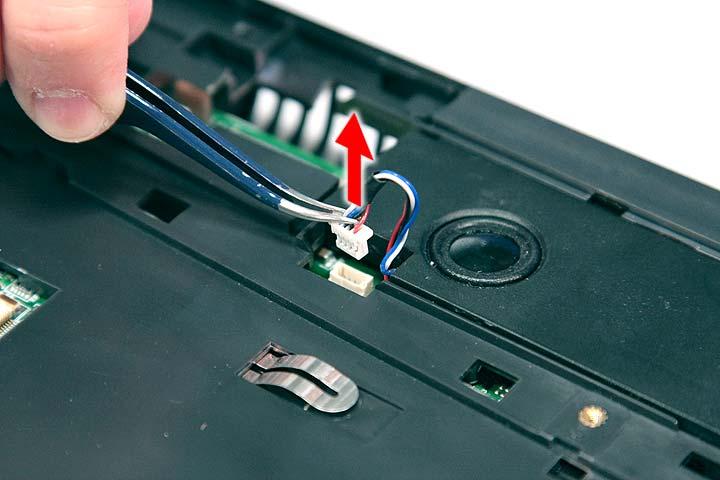
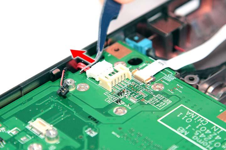
14. See “Removing the VGA Board (Discrete Model only)” on page 73. 15. See “Removing the LCD Module” on page 74. 16. See “Separating the Upper Case from the Lower Case” on page 76. 17. See “Removing the Modem Board” on page 85. 18. See “Removing the USB Board Module” on page 87. 19. Disconnect the Bluetooth cable from BLUE1 on the main board.
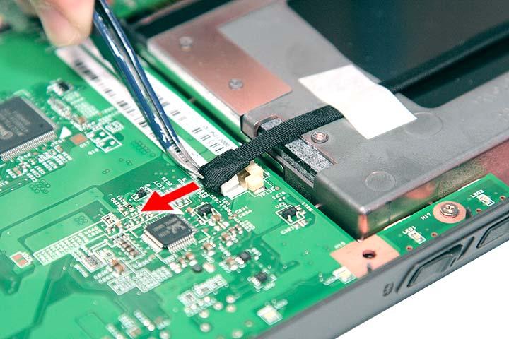
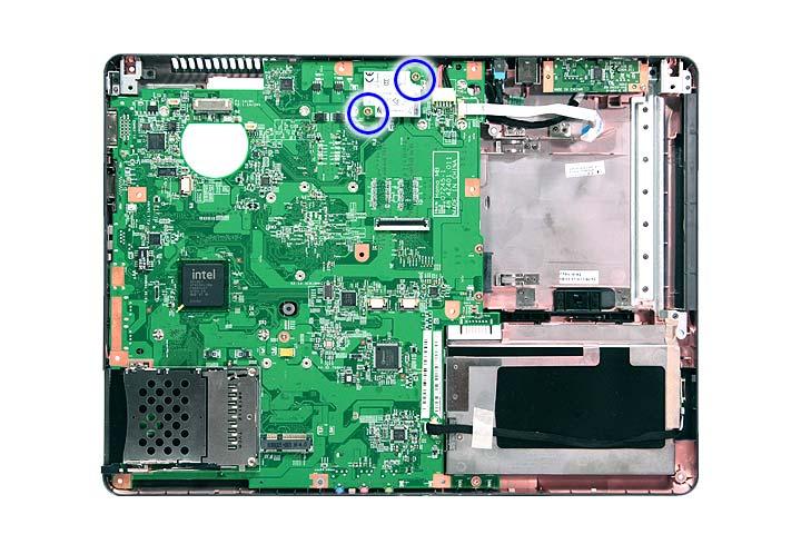
20. Disconnect the DC cable from the DC1 connector on the main board.
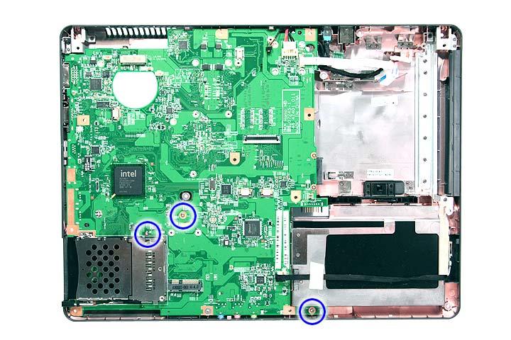
Step Size (Quantity) Color Torque 1~3 M2 x L4 (3) Silver 1.6 kgf-cm
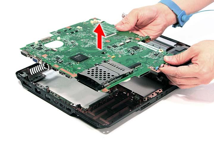
22. Carefully remove the main board.
LCD Module Disassembly Flowchart LCD MODULE DISASSEMBLY
LCDMODULE
LCDBEZEL Cx4
Gx6,B2
LCD ASSEMBLY
LCD FPC CABLE Bx2
LEFT LCD BRACKET Bx2
RIGHT LCD BRACKET LCD BACK PANEL
ANTENNAS
VGA CAMERA
Screw List
Item Screw Color Part No.
B M2 x L4 Silver 86.9A552.4R0
C M2.5 x L5 Black 86.00E33.736
G M2.5 x L5 Black 86.00F87.735
1. See “Removing the Battery Pack” on page 54. 2. See “Removing the SD dummy card” on page 55. 3. See “Removing the PC and ExpressCard dummy cards” on page 56. 4. See “Removing the Lower Cover” on page 57. 5. See “Removing the WLAN Board Modules” on page 59. 6. See “Removing the Middle Cover” on page 66. 7. See “Removing the Keyboard” on page 69. 8. See “Removing the LCD Module” on page 74. 9. Remove the four screw covers from the LCD bezel.
10. Remove the four screws (C) on the LCD module as shown.

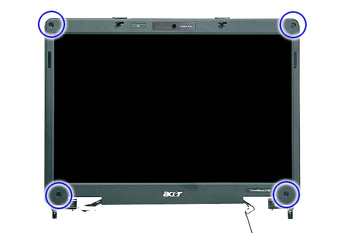
Step Size (Quantity) Color Torque 1~4 M2.5 x L6 (4) Black 3.0 kgf-cm
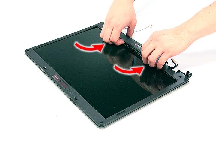
12. Disconnect the microphone cable and remove the bezel from the LCD panel.
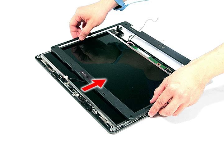
1. See “Removing the Battery Pack” on page 54. 2. See “Removing the SD dummy card” on page 55. 3. See “Removing the PC and ExpressCard dummy cards” on page 56. 4. See “Removing the Lower Cover” on page 57. 5. See “Removing the WLAN Board Modules” on page 59. 6. See “Removing the Middle Cover” on page 66. 7. See “Removing the Keyboard” on page 69. 8. See “Removing the LCD Module” on page 74. 9. See “Removing the LCD Bezel” on page 92. 10. Disconnect the cable from the web camera.
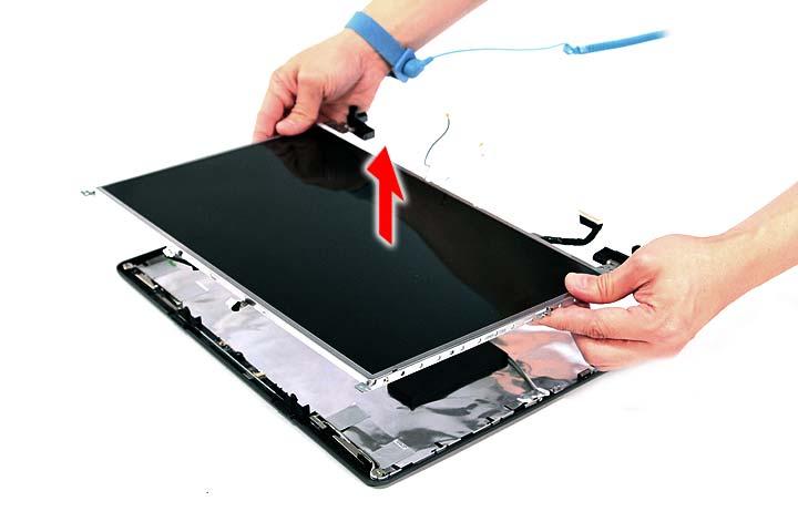
11. Remove the eight screws (6 x G, 2 x B) securing the LCD module.
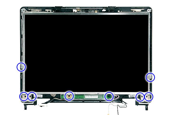
Step Size (Quantity) Color Torque 1~6 M2.5 x L6 (6) Black 2.5 kgf-cm 7~8 M2 x L4 (2) Silver 1.6 kgf-cm
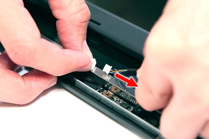
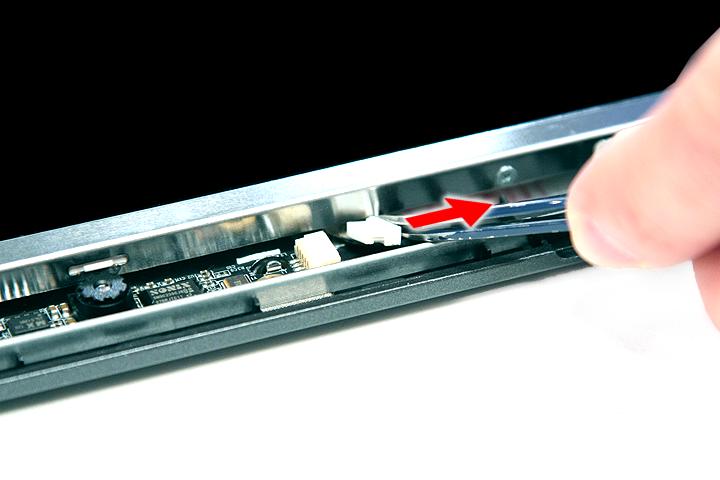
Removing the FPC Cable
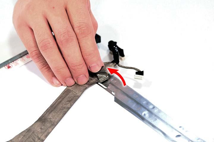
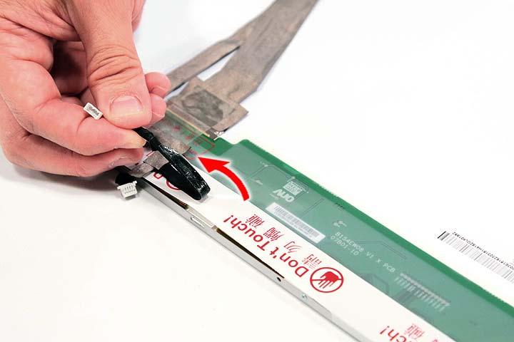
1. See “Removing the Battery Pack” on page 54. 2. See “Removing the SD dummy card” on page 55. 3. See “Removing the PC and ExpressCard dummy cards” on page 56. 4. See “Removing the Lower Cover” on page 57. 5. See “Removing the WLAN Board Modules” on page 59. 6. See “Removing the Middle Cover” on page 66. 7. See “Removing the Keyboard” on page 69. 8. See “Removing the LCD Module” on page 74. 9. See “Removing the LCD Bezel” on page 92. 10. See “Removing the LCD module with the Brackets” on page 94. 11. Disconnect the cables from the inverter board.
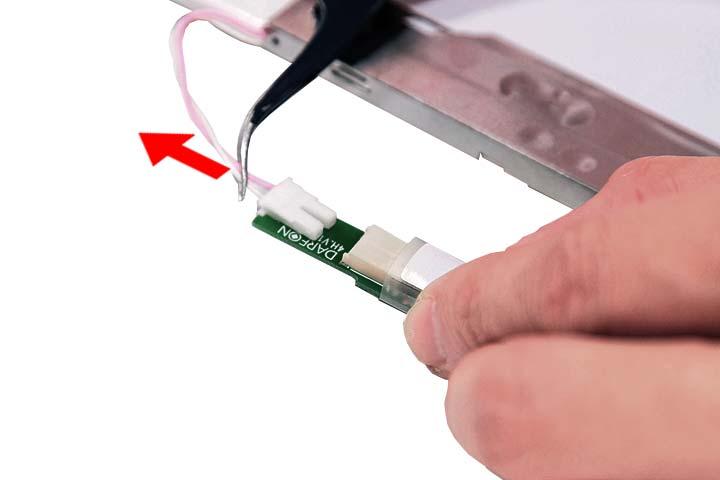

12. Detach any adhesive tapes and any cable that is glued to the LCD panel.