1 minute read
Removing the Main Board


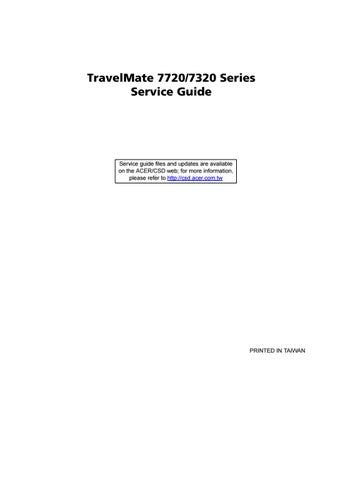
WARNING:The touchpad board is glued to the upper case, only remove the touchpad board if it is defective.
1. See “Removing the Battery Pack” on page 62. 2. See “Removing the SD dummy card” on page 63. 3. See “Removing the PC and ExpressCard dummy cards” on page 63. 4. See “Removing the Lower Cover” on page 64. 5. See “Removing the Secondary HDD Cover” on page 65. 6. See “Removing the Secondary HDD Bracket and Connector” on page 66. 7. See “Removing the DIMM” on page 68. 8. See “Removing the WLAN Board Modules” on page 68. 9. See “Removing the Hard Disk Drive Module” on page 69. 10. See “Removing the Optical Drive Module” on page 70. 11. See “Removing the Modem Board” on page 73. 12. See “Removing the Heatsink Fan Module” on page 74. 13. See “Removing the CPU and VGA Heatsink Module” on page 75. 14. See “Removing the CPU” on page 77. 15. See “Removing the VGA board (for Discrete model only)” on page 77. 16. See “Removing the Middle Cover and the Power Board” on page 78. 17. See “Removing the Keyboard” on page 80. 18. See “Removing the LCD Module” on page 81. 19. See “Separating the Upper Case from the Lower Case” on page 84.
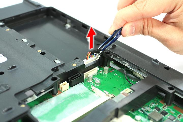
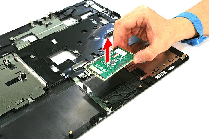
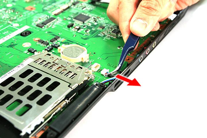
21. Disconnect the Bluetooth cable from the BLUE1 connector on the main board.
22. Disconnect the speaker cable from the SPKR1 on the main board.
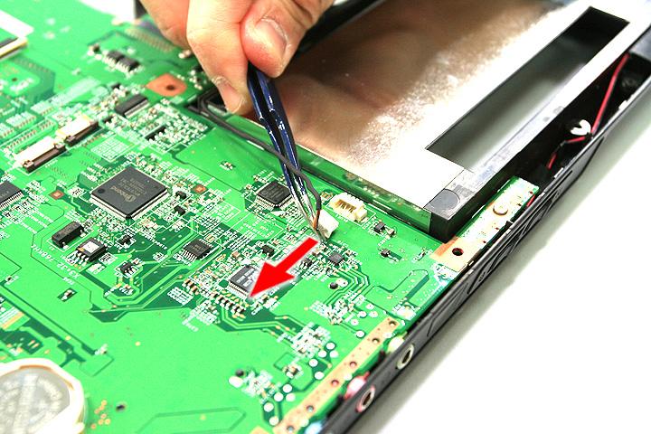
23. Remove the four screws (C) holding the main board.
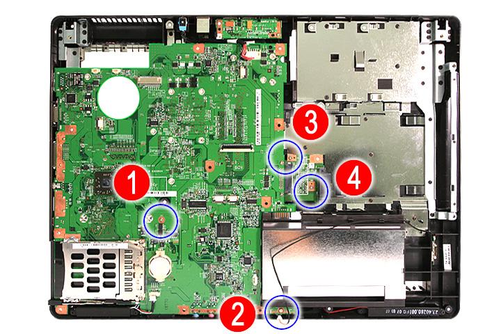
Step Size (Quantity) Color Torque
1~4 M2 x L4 (4) Silver 1.6 kgf-cm