1 minute read
Removing the LCD Module


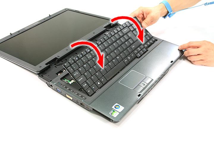
5. Disconnect the keyboard cable from the main board to remove the keyboard.


1. See “Removing the Battery Pack” on page 62. 2. See “Removing the Lower Cover” on page 64. 3. See “Removing the WLAN Board Modules” on page 68. 4. See “Removing the Middle Cover and the Power Board” on page 78. 5. See “Removing the Keyboard” on page 80.

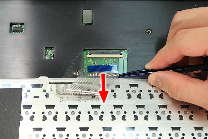
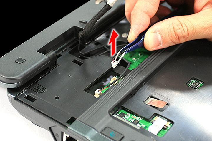
7. Remove the internal microphone cable from the INTMIC1 connector on the main board and release the cables from the latches.


9. Remove the two screws (A) from the base of the unit.

Step Size (Quantity) Color Torque
1~2 M2.5 x L6 (2) Black 4.0 kgf-cm
10. Remove the two screws (H) from the left and right hinge of the LCD module.

Step Size (Quantity) Color Torque
1~2 M2.5 x L8 (2) Black 4.0 kgf-cm