7 minute read
Main Unit Reassembly


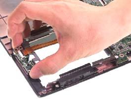
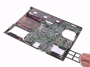
1. Place the mainboard back to the lower case.
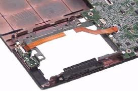
2. Insert the PCMCIA dummy card back to the lower case.
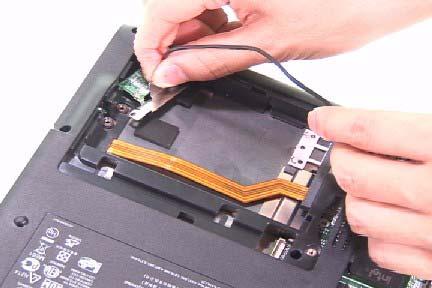
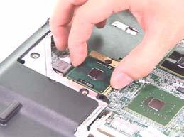
3. Connect the USB FFC to the USB module and latch it well. 4. Place the USB module back to the lower case.
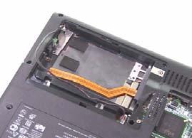
5. Secure the USB module with one screw. 6. Connect the USB FFC to the mainboard and latch it well.
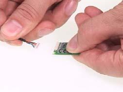
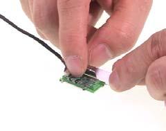
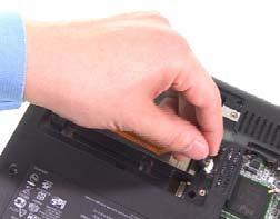
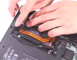
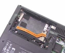
7. Connect the MDC cable to the MDC board. 8. Place the MDC board back to the mainboard.


10. Connect the speaker cable to the mainboard.

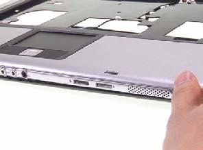
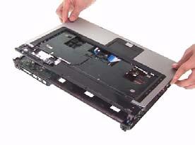
11. Aim the location of Bluetooth and wireless launch button. 12. Place the upper case back to the lower case.
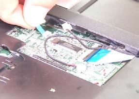
13. Connect the touchpad board FFC to the mainboard and latch it well.


14. Connect the MIC wire cable to the mainboard.


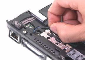
16. Connect the Audio DJ FFC to the mainboard. 17. Connect the LID switch cable back to the mainboard.
18. Secure the lower case with 22 screws.

19. Secure the upper case with 5 screws.

Reassembling the ODD
1. Place the ODD module back to the main unit.


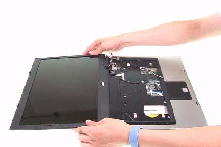
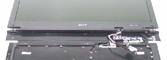
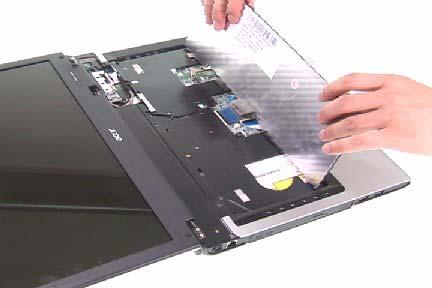
Reassembling the LCD Module to Main Unit
1. Place the LCD module back to the main unit. 2. Put the antenna through the hole.
3. Secure the LCD module with two screws on left and right hinges.
4. Connect the LCD cable to the mainboard.
5. Place the keyboard back to the main unit. 6. Connect the keyboard FFC to the mainboard and latch it well.
7. Turn the keyboard over.


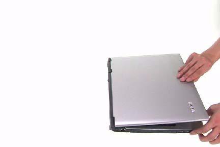
9. Place the middle cover back to the main unit. 10. Close the notebook.

11. Secure the middle cover with three screws on the rear panel.
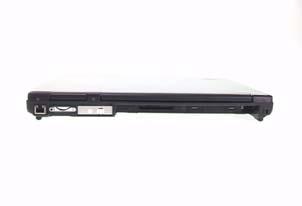
12. Connect the power cable to the mainboard.


Reassembling the Bluetooth Module
1. Connect the Bluetooth cable to the Bluetooth module. 2. Place the Bluetooth module to the Bluetooth bracket.
3. Secure the Bluetooth bracket with the two screws.

5. Secure the Bluetooth module with one screw. 6. Connect the Bluetooth cable to the mainboard.

7. Place the Bluetooth cable in the wire groove.
Reassembling the CPU
1. Aim the pin position on the CPU socket, then place the CPU back to the socket. 2. Use a flat screw driver and turn the screwdriver clockwise to lock the CPU.

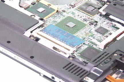
1. Place the DDR memory back to the mainboard as shown and press it down to latch it.

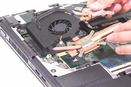
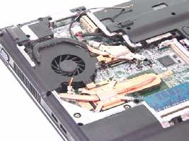
Reassembling the Heatsink module
1. Place the heatsink module back to the main unit. 2. Secure the heatsink module with the seven screws.
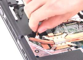
3. Connect the main fan cable to the mainboard.

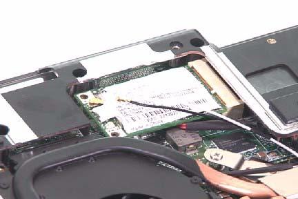
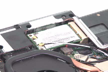
Reassembling the Wireless Card
1. Place the wireless card back to the mainboard as shown. 2. Secure the wireless card with two screws.


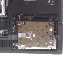
Reassembling the HDD
1. Place the HDD back to the main unit. 2. Secure the HDD with one screw.
3. Place the HDD cover back to the main unit. 4. Secure the HDD cover with the two screws.


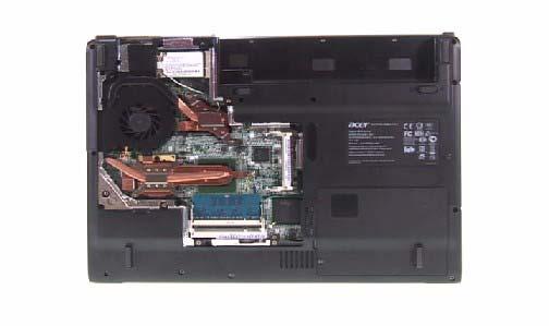
Reassembling the heatsink cover & Battery
1. Aim the three hooks to the holes on the rear panel and place the heatsink cover back to the lower case.
2. Secure the heatsink cover with six screws.


4. This completes the main unit reassembly.
Troubleshooting
Use the following procedure as a guide for computer problems. NOTE: The diagnostic tests are intended to test this model. Non-Acer products, prototype cards, or modified options can give false errors and invalid system responses. 1. Duplicate symptom and obtain the failing symptoms in as much detail as possible. 2. Distinguish symptom. Verify the symptoms by attempting to re-create the failure by running the diagnostic test or by repeating the same operation. 3. Disassemble and assemble the unit without any power sources. 4. If any problem occurs, you can perform visual inspection before you fellow this chapter’s instructions. You can check the following: power cords are properly connected and secured; there are no obvious shorts or opens; there are no obviously burned or heated components; all components appear normal. 5. Use the following table with the verified symptom to determine which page to go to.
Symptoms (Verified) Power failure. (The power indicator does not go on or stay on.) POST does not complete. No beep or error codes are indicated.
POST detects an error and displayed messages on screen. Other symptoms (i.e. LCD display problems or others). Symptoms cannot be re-created (intermittent problems). Go To “Power System Check” on page 95.
“Power-On Self-Test (POST) Error Message” on page 97 “Undetermined Problems” on page 109 “Error Message List” on page 98
“Power-On Self-Test (POST) Error Message” on page 97 Use the customer-reported symptoms and go to “Power-On Self-Test (POST) Error Message” on page 97 “Intermittent Problems” on page 108 “Undetermined Problems” on page 109