1 minute read
Disassembly Procedure Flowchart


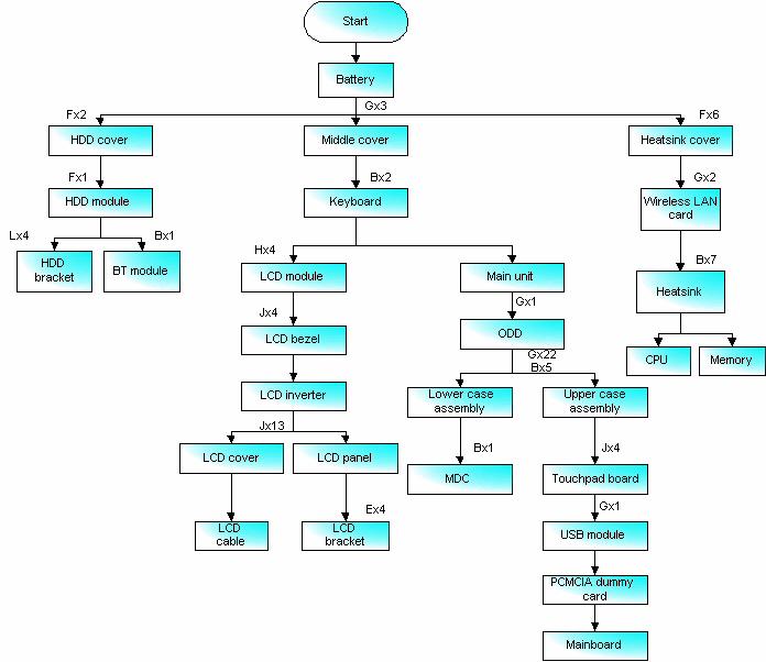
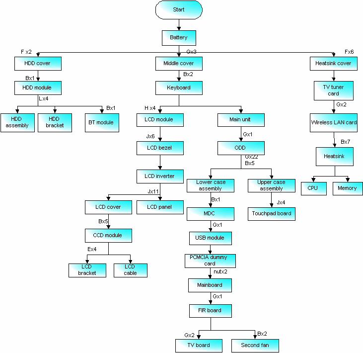
The flowchart on the succeeding page gives you a graphic representation on the entire disassembly sequence and instructs you on the components that need to be removed during servicing. For example, if you want to remove the main board, you must first remove the keyboard, then disassemble the inside assembly frame in that order.
No Partname
Part No A SCREW M2.5*3.5-I(NI)(NYLOK) 86.AAV7.001 B SCWER M2.5*3.0I(BNI)(NYLOK)EP 86.T25V7.012 C SCREW M2.0*5.0 I-(BNI)(NYLOK) 86.T23V7.015 D SCREW M2.5-0.45*3.5-F(ANTI-LOOSE) 86.AA7V7.002 E SCREW M2.0*3.0-I-NI-NYLOK TBD F SCREW M2.5*4-I(BNI) 86.T23V7.019 G SCREW M2.5*6-I(BNI)(NYLOK) 86.A08V7.004 H SCREW M2.5*6.0-P(NI)(NYLOK) 86.AA7V7.003 I SCREW M1.7*3.0-I(BK) 86.T50V7.001 J SCREW M2.5*5.0-I(NI)(NYLOK) 86.T23V7.010 K SCREW M2.0*5-I(NI)(NYLOK) 86.T23V7.006 L SCREW M3*0.5+3.5I TBD