25 minute read
Chapter 1 System Specifications


System Specifications
Features
This computer was designed with the user in mind. Here are just a few of its many features:
Performance
! Intel® Mobile Pentium® and Celeron® CPU families 700/900 MHz processor with 128KB cache ! 64-bit memory bus ! AcerMedia bay (removable CD-ROM or DVD-ROM drive) ! Built-in floppy drive ! High-capacity, Enhanced-IDE hard disk ! NiMH main battery pack ! Power management system with ACPI (Advanced Configuration Power Interface)
Multimedia
! 16-bit high-fidelity AC’97 stereo audio with 3D sound and wavetable synthesizer ! Built-in dual speakers with microphone ! High-speed CD-ROM and DVD-ROM drive(AcerMedia Bay) ! USB video capture kit option
Connectivity
! PS/2 interface, which also can be configured as keyboard/keypad interface. ! 84/85/88 key keyboard, which is IBM PC/AT keyboard compatible. ! Universal Serial Bus Ports ! CD-ROM/DVD Swappable Module ! RJ-11 for 56Kbps fax/modem ! Upgradeable memory and hard disk ! ECP/EPP Compliant parallel port. ! RS-232 (16550 compatible) serial port
Human-centric Design and Ergonomics
! All-in-one design (CD-ROM, floppy disk drive, hard disk drive) ! Sleek, smooth and stylish design ! Full-sized keyboard ! Ergonomically centred touchpad pointing device
Expansion
! One Type III or one Type II CardBus PC card (formerly PCMCIA) slot with ZV (zoomed video) support ! Upgradeable memory and hard disk
Display
! 12.1”, 13.3” or 14.1” TFT LCD displaying 32-bit true-color at 800X600 SVGA or 1024x768 XGA resolution
! 3D capabilities ! Supports other output display devices such as LCD projection panels for large audience presentations ! “Automatic LCD dim” feature that automatically decides the best settings for your display and conserves power. ! Simultaneous LCD and CRT display support ! Dual display capability
Video performance
2X AGP video graphic accelerator with 8MB shared from system memory to boost video performance.
Simultaneous display
The computer’s large display and multimedia capabilities are great for giving presentations. If you prefer, you can also connect an external monitor when giving presentations. This computer has built-in AGP and VGA display system to support simultaneous LCD and CRT display. Simultaneous display allows you to control the presentation from your computer and at the same time face your audience. You can also connect other output display devices such as LCD projection panels for large-audience presentations.
Dual Display
The computer’s unique graphics chip takes advantage of Windows ME’s multi-display capability, allowing you to extend your desktop to an external display device, such as an external monitor projector. With this feature enabled, you can move program windows to/from the computer LCD and the external monitor.
Power management
The power management system incorporates an "automatic LCD dim" feature that automatically dims the LCD when the computer is powered by a battery pack to conserve battery power. See “Power Management” on page 26 for more information on power management features.
Opening and closing the display
To open the display, slide the display cover latch to the left and lift up the cover. Then tilt it to a comfortable viewing position. The computer employs a microswitch that turns off the display (and enters standby mode) to conserve power when you close the display cover, and turns it back on when you open the display cover. NOTE: If an external monitor is connected, the computer turns off the display (but does not enter standby mode) when you close the display cover. To close the display cover, fold it down gently until the display cover latch clicks into place.
WARNING: To avoid damaging the display, do not slam it when you close it. Also, do not place any object on top of the computer when the display is closed.
CLK GEN.
ICS9248-157
SDRAM CLK BUFFER
ICS-9112-17
INT. SPKR
INT. SPKR OP AMP
TPA0202
Mobile PIII
Celeron
DIMM*2
MEM BUS
LINE IN
VR AC Link
AC '97Codec CS4299 or ALC200
MODEM Daughter Card
MIC HOST BUS
N/B
S/B LCD
CRT
Primary EIDE
HDD PCI BUS
USB*2
Secondary EIDE
CDROM CARDBUS
OZ6912
DEBUG BIOS ROM MX29F004 KBC M38867 XD BUS
Finger Print
RTC BQ3285LF
CMOS BAT
Floppy Printer Serial
TOUCH PAD INT. KB PS/2 CONN
Top View
10
11
12
13
14
15 9 8 7 6 5 4 3 2 1
23
22
21 20 19 18
16 17
1 DC-in Port 13 PCMCIA Socket Connector 2 PS/2 Keyboard and Mouse Port 14 Diskette Drive Connector 3 Serial Port 15 PCMCIA (PC card)Controller (OZ6812) 4 Parallel Port 16 HDD Connector 5 Launch Key Connector 17 BIOS ROM 6 USB Port 1 18 Touch Pad Cable Connector 7 USB Port 2 19 Switch 8 External Display Port 20 Keyboard Cable Connector 9 Modem Port 21 RTC battery 10 LED & Inverter Connector 22 CD-ROM Connector 11 Fan Connector 23 LCD Connector 12 CPU (on board)
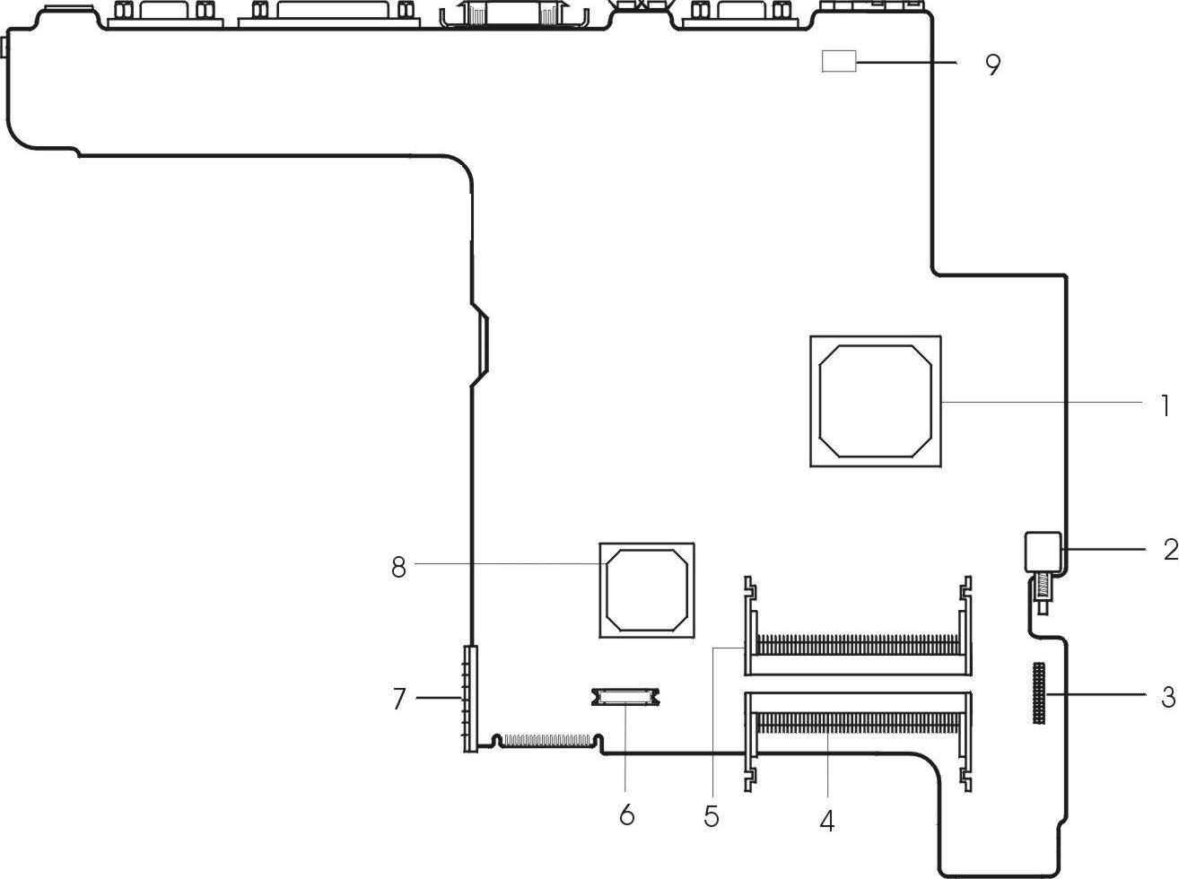
1 North Bridge (ALi M1632M) 6 Modem Connector 2 Power Push Switch 7 Battery Connector 3 Audio Connector 8 South Bridge (ALi M1535) 4 DIMM 2 Socket 9 Modem Card Cable Connector 5 DIMM 1 Socket
Ports allow you to connect peripheral devices to your computer as you would with a desktop PC.
Front Panel
# Item Description
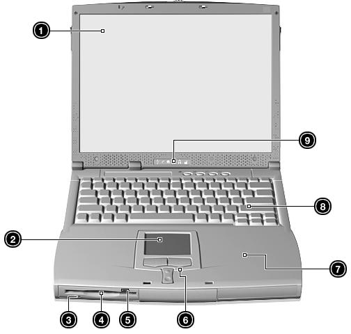
1 Display screen Also called LCD (Liquid Crystal Display), displays computer output. 2 Touchpad Touch-sensitive pointing device which functions like a computer mouse. 3 Floppy activity indicator LED(light-emitting diodes) that turn on and off when the floppy is active. 4 Floppy drive Internal diskette drive, accepts 3.5-inch floppy diskettes 5 Floppy disk eject button Push this button to eject the foppy disk 6 Click button (left, center and right) The left and right buttons function like the left and right mouse buttons, the center button serves as a scroll up/ down button. 7 Palmrest Comfortable support area for your hands when you use the computer. 8 Keyboard Inputs data into your computer. 9 Status indicators LEDs (Light Emitting Diodes) that turn on and off to show the status of the computer and its functions and components.
# Icon Item/ Port Connects to...
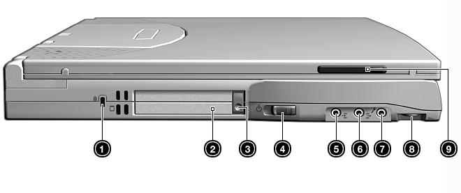
1 Security keylock Kensington-compatible key-based computer security lock. 2 PCMCIA (PC card) Port Connects to one Type II or one Type III 16-bit PC card or 32-bit CardBus PC Card. 3 Eject button Eject PC cards from the card slots. 4 Power switch Turns on the computer power. 5 Speaker/ headphone-out jack Connects to audio line-out devices (e.g., speakers, headphones) 6 Line-in jack Accepts audio line-in devices (e.g., audio CD player, stereo walkman). 7 Microphone-in jack Accepts a mono/stereo condenser microphone. 8 Volume control Controls the volume of the speakers. 9 Video capture kit slot Accepts the video capture kit option on the left side of the computer.
# Icon Item/ Port Connects to...
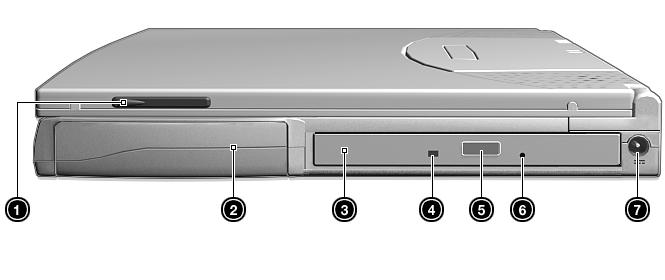
1 Video capture kit slot Accepts the video capture kit option on the right side of the computer. 2 Battery bay Houses the computer’s battery pack. 3 AcerMedia drive Houses removable media drive modules. 4 LED indicator Lights up when the AcerMedia drive is active. 5 Eject button Ejects the compact disc from the drive. 6 Emergency eject slot Ejects the compact discs when the computer is turned off. 7 Power Jack Connects to an AC adapter
Rear Panel
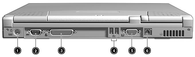
# Icon Port Connects to...
1 PS/2 port Connects to any PS/2-compatible devices (e.g., PS/2 keyboard/mouse/keypad) 2 Serial port Connects to a serial device (e.g., serial mouse)
# Icon Port
Connects to...
3 Parallel port Connects to a parallel device (e.g., parallel printer)
4 USB port (two) Connects to any Universal Serial Bus devices(e.g., USB mouse, USB camera).
5 External display port Connects to a display device (e.g., external monitor, LCD projector) and displays up to 64K colors at 1280x1024
6 Modem jack Connects to the phone line
Bottom Panel
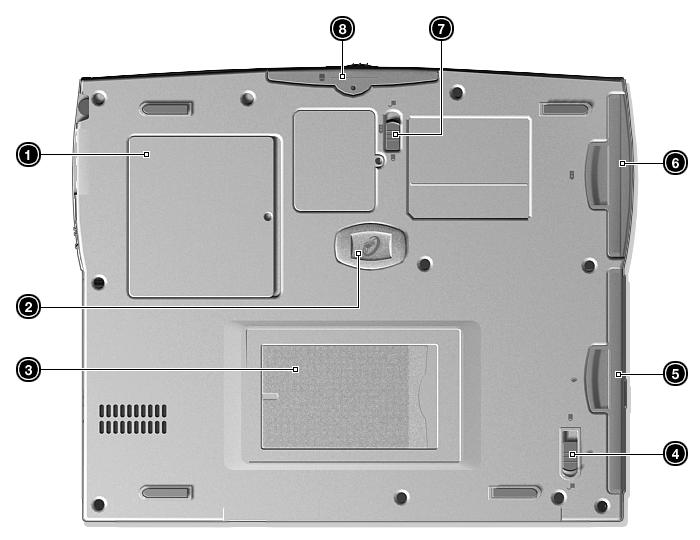
# Item Description
1 Memory compartment Houses the computer’s main memory. 2 Hard disk anti-shock protection Protects your hard disk against shocks. 3 Personal identification slot Insert a business card or similar-sized identification card to personalize your computer. 4 AcerMedia bay release latch Unlatches the AcerMedia drive for removal or swapping. 5 AcerMedia bay Houses an AcerMedia drive module. 6 Battery bay Houses the computer’s battery pack. 7 Battery release latch Unlatches the battery to remove the battery pack. 8 Hard disk bay Houses the computer’s hard disk (secured by a screw).
The computer has six easy-to-read status icons on the right of the display screen
The Power and Standby status icons are visible even when you close the display cover so you can see the status of the computer while the cover is closed.
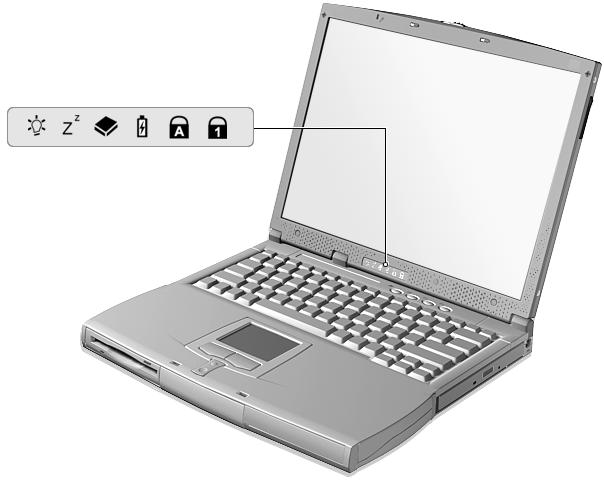
# Icon Function Description
1 Power Lights when the computer is on.
2 Sleep Lights when the computer enters Standby mode and blinks when it enters into or resumes from hebernation mode. 3 Media Activity Lights when the floppy drive, hard disk or AcerMedia drive is active.
4 Battery Charge Lights when the battery is being charged.
5 Caps Lock Lights when Caps Lock is activated.
6 Num Lock (Fn-F11) Lights when Numeric Lock is activated.
The keyboard has full-sized keys and an embedded keypad, separate cursor keys, two Windows keys and twelve function keys.
Special keys
Lock keys
The keyboard has three lock keys which you can toggle on and off.
Embedded numeric keypad
The embedded numeric keypad functions like a desktop numeric keypad. It is indicated by small characters located on the upper right corner of the keycaps. To simplify the keyboard legend, cursor-control key symbols are not printed on the keys.
Lock key Description
Caps Lock When Caps Lock is on, all alphabetic characters typed are in uppercase. Num Lock (Fn-F11) When Num Lock is on, the embedded keypad is in numeric mode. The keys function as a calculator (complete with the arithmetic operators ), -, *, and /). Use this mode when you need to do a lot of numeric data entry. A better solution would be to connect an external keypad. Scroll Lock (Fn-F12) When Scroll Lock is on, the screen moves one line up or down when you press the up or down arrow keys respectively. Scroll Lock does not work with some applications.
Desired access Num lock on Num lock off
Number keys on embedded keypad Cursor-control keys on embedded keypad Type numbers in a normal manner.
Hold Shift while using cursor-control keys. Hold Fn while using cursor-control keys.
Main keyboard keys Hold Fn while typing letters on embedded keypad. Type the letters in a normal manner.
NOTE: If an external keyboard or keypad is connected to the computer, the Num Lock feature automatically shifts from the internal keyboard to the external keyboard or keypad.
Windows keys
The keyboard has two keys that perform Windows-specific functions.
Keys Description
Windows logo key !!!!!"
Start button. Combinations with this key perform shortcut functions. Below are a few examples: " + Tab (Activates next taskbar button) " + E (Explores My Computer) " + F (Finds Document) " + M (Minimizes All) Shift + " + M (Undoes Minimize All) " + R (Displays the Run... dialog box) Application key Opens a context menu (same as a right-click).
The computer employs hot keys or key combinations to access most of the computer’s controls like screen contrast and brightness, volume output and the BIOS Utility. To activate hot keys, press and hold the Fn key before pressing the other key in the hot key combination.
Hot Key Icon Function Description
Fn-F1 Hotkey help Displays a list of the hotkeys and their functions.
Fn-F2 Setup Accesses the notebook configuration utility.
Fn-F3 Power Scheme Toggle Switches between the power management scheme used by the computer (function available if supported by operating system).
Fn-F4 Sleep Puts the computer in Sleep mode.
Fn-F5 Display toggle Switches display output between the display screen, external monitor (if connected) and both the display screen and external monitor.
Fn-F6 Screen blank Turns the display screen backlight off to save power. Press any key to return.
Fn-F7 Touchpad Toggle Turns the internal touchpad on and off.
Fn-F8 Speaker on/off Turns the speakers on and off; mutes the sound.
Fn-↑
Fn-↓
Fn-→ Contrast up Increases the screen contrast (available only for models with HPA displays).
Contrast down Decreases the screen contrast (available only for models with HPA displays).
Brightness up Increases the screen brightness.
Fn-← Brightness down Decreases the screen brightness.
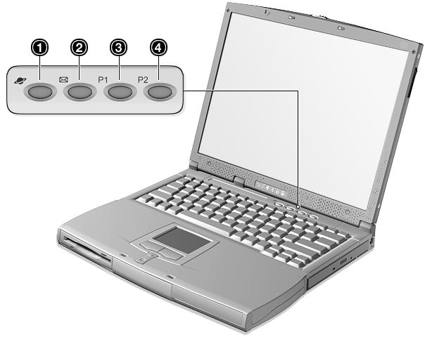
Launch Keys
Located at the top of the keyboard are four buttons. These buttons are called launch keys. They are designated as key 1, key 2, key 3 and key 4. By default, key 1 is used to launch the internet browser and key 2 is used to launch the e-mail application. Keys 3 and 4 starts the Launch Manager application. All four keys can be set by the user. To set the launch keys, run the Acer Launch Manager.
The built-in touchpad is a PS/2-compatible pointing device that senses movement on its surface. This means that the cursor responds as you move your finger on the surface of the touchpad. The central location on the palmrest provides optimum comfort and support. NOTE: When using an external USB or serial mouse, you can press Fn-F7 to disable the touchpad. If you are using an external PS/2 mouse, the touchpad is automatically disabled.
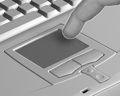
Touchpad basics
The following items teach you how to use the touchpad:
1. Move your finger across the touchpad to move the cursor. 2. Press the left (1) and right (3) buttons located on the edge of the touchpad to do selection and execution functions. These two buttons are similar to the left and right buttons on a mouse. Tapping on the touchpad produces similar results. 3. Use the center (2) buttons (top and bottom) to scroll up or down a page. This button mimics your cursor pressing on the right scroll bar of Windows applications.
Function Left Button Right Button Center Button
Tap
Execute Click twice quickly Tap twice (at the same speed as doubleclicking a mouse button) Select Click once Tap once Drag Click and hold, then use finger to drag the cursor on the touchpad Tap twice (at the same speed as doubleclicking a mouse button) then hold finger to the touchpad on the second tap and drag the cursor
Access context menu Click once
Scroll Click and hold the up/ down buttons
NOTE: Keep your fingers dry and clean when using the touchpad. Also keep the touchpad dry and clean. The touchpad is sensitive to finger movements. Hence, the lighter the touch, the better the response. Tapping harder will not increase the touchpad’s responsiveness.
System Board Major Chips
Item Controller
System core logic ALI M1632M with DRAM/Cache controller Super I/O controller ALI M1535 Audio controller Cirrus Logic CS4299 or Realtek ALC200 Audio Codec 97 Video controller Trident VGA integrated by north bridge ( 8MB viseo RAM shared from system memory) Hard disk drive controller Embedded in M1535 Keyboard controller M38867 RTC BQ3285LF
Processor
Item Specification
CPU type Intel Celeron 700-900 MHz processor with 128K cache CPU package uBGA2 CPU core voltage 1.6V CPU I/O voltage 1.5V
BIOS
Item Specification
BIOS vendor Acer BIOS BIOS Version V3.3 BIOS ROM type Flash ROM BIOS ROM size 512KB BIOS package 32 Pin PLCC Supported protocols ACPI 1.0b, APM 1.2, PC Card 95, SM BIOS 2.3, EPP/IEEE 1284, ECP/ IEEE 1284 1.7 & 1.9, IrDA, PCI 2.1, PnP 1.0a, PS/2 keyboard and mouse, USB, VESA VGA BIOS, DDC-2B, CD-ROM bootable, Windows keyboard Microsoft Simple Boot Flag BIOS password control Set by switch, see SW1 settings
Second Level Cache
Item
Cache controller Built-in CPU Cache size 128KB 1st level cache control Always Enabled 2nd level cache control Always Enabled Cache scheme control Fixed-in write back
System Memory
Item
Memory controller ALI M1632 Onboard memory size 0MB DIMM socket number 2 Sockets Supports memory size per socket 32/64/128/256 MB Supports maximum memory size 512 MB ( 256MB x 2 )
Specification
Specification
Item Specification
Supports DIMM type SDRAM Supports DIMM Speed 100 MHz Supports DIMM voltage 3.3 V Supports DIMM package 144-pin so-DIMM Memory module combinations You can install memory modules in any combinations as long as they match the above specifications .
Memory Combinations
Slot 1
Slot 2
64MB 0MB 64 MB 0MB 64MB 64 MB 64MB 32MB 96 MB 32MB 64MB 96 MB 64MB 64MB 128 MB 0MB 128MB 128 MB 128MB 0MB 128 MB 32MB 128MB 160 MB 128MB 32MB 160 MB 64MB 128MB 192 MB 128MB 64MB 192 MB 128MB 128MB 256 MB 256MB 0MB 256MB 0MB 256MB 256MB 256MB 32MB 288MB 32MB 256MB 288MB 256MB 64MB 320MB 64MB 256MB 320MB 256MB 128MB 384MB 128MB 256MB 384MB 256MB 256MB 512MB
Total Memory
Above table lists some system memory configurations. You may combine DIMMs with various capacities to form other combinations. NOTE: The shipping specification for DIMM combination is 64MB in slot 1.
Modem Interface
Item Specification
Chipset Ambit MDC module with Lucent modem controller Fax modem data baud rate (bps) 14.4K Data modem data baud rate (bps) 56K Supports modem protocol V.90MDC Modem connector type RJ11 Modem connector location Rear side
Floppy Disk Drive Interface
Item Specification
Vendor & model name MCI JU-226A252FC Floppy Disk Specifications Media recognition 2DD ( 720KB ) 2HD (1.2 MB, 3 mode ) 2HD (1.44MB ) Sectors/track 9 15 18 Tracks 80 80 80 Data transfer rate (Kbit/s) 1 MB 1.6 MB 2 MB Rotational speed (RPM) 300 360 300 Read/write heads 2 Encoding method MFM Power Requirement Input Voltage (V) +5V
Hard Disk Drive Interface
Item
Specification
Vendor & Model Name IBM (DJSA-205) IBM (DJSA-210) Capacity (MB) 10000 5000 Bytes per sector 512 512 Logical heads 16 15 Logical sectors 63 63 Drive Format Logical cylinders 19485 10336 Physical read/write heads 2 1 Disks 1 1 Spindle speed (RPM) 4200RPM 4200RPM Performance Specifications Buffer size 512KB 512KB Interface ATA-5 ATA-5 Data transfer rate (diskbuffer, Mbytes/s) 109-203 109-203 Data transfer, rate (host~buffer, Mbytes/s) 66.6 MB/Sec DC Power Requirements Voltage tolerance 5 +/- 5% 5 +/- 5%
CD-ROM Interface
Items
Specification
Vendor & Model Name MKE CR-177-B/D TEAC CD-224E-B26 Performance Specification Transfer rate CAV Mode: 775~1800 blocks/sec Mode 1: 1550~3600 kBytes/sec Mode 2: 1768~4106kBytes/sec Read Sustained: 1545~3600 KB/sec Programmed I/O: 16.7 MB/sec Max. (Mode 0~4) Multi-word DMA: 16.7 MB/sec Max. (Mode 0~2) Ultra DMA: 33.3MB/sec Max.
Access time (typ.) Random: 100 ms Full Stroke: 200 ms
Random: 115 ms Full Stroke: 250 ms Rotation speed 5000 rpm 5136 rpm Data Buffer Capacity 128 KB 128 KB Interface IDE IDE Applicable disc format CD-Audio, CD-ROM (mode 1 and Mode 2), CD-ROM XA (mode 2, form 1 and form 2), CD-I (mode 2, form 1 and form 2), CD-I Ready, CD-I Bridge, Photo CD, CD-WO, Video CD, Enhanced Music CD (CD Plus), CD-RW CD/CD-ROM(12cm,8cm), CD-R, CD-RW, CD-DA, CD-ROM(Mode 1, Mode2), CDROM XA (Mode 2, Form1 and Form 2), Photo CD(Singal, Multi- sesseion), Enhanced CD
Loading mechanism Drawer with soft eject and emergency eject hole Drawer with soft eject and emergency eject hole
Power Requirement Input Voltage +5V[DC]+/-5% +5V[DC]+/-5%
DVD-ROM Interface
Item
Specification
Vendor & model name MKE SR-8175-BXX Performance Specification With CD Diskette With DVD Diskette Transfer rate (KB/sec) Average Sustained: CAV mode 775~1800 blocks/sec (10.3X to 24X) 1550~3600kBytes/sec (Mode 1) 1768~4106 kBytes/sec (Mode 2) DVD-5: Normal Speed (1X) 11.08 Mbits/sec CAV mode 36.67~88.64 Mbits/sec DVD-9/DVD-R: Normal Speed (1X) 11.08 Mbits/sec CAV mode 36.67~88.64 Mbits/sec
Average Full Access time (typ.) Random (*1) CAV mode 110 msec typical 150 msec average max Full Stroke (*2) CAV mode 200 msec typical 260 msec average max
Data Buffer Capacity 512 kBytes DVD-5: Random (*4) 150 msec typical 200 msec average max Full Stroke (*5) 300 msec typical 400 msec average max DVD-9: Random (*7) 170 msec typical 230 msec average max Full Stroke (*8) 340 msec typical 470 msec average max
Item Specification
Interface IDE Applicable disc format DVD: DVD-5, DVD-9, DVD-10, DVD-R (3.95G) CD: CD-Audio, CD-ROM (mode 1 and mode 2), CD-ROM XA (mode 2, form 1 and form 2), CD-I (mode 2, form 1 and form 2), CD-I Ready, CD-I Bridge, CD-WO, CD-RW, Photo CD, Video CD, Enhanced Music CD, CD-TEXT Loading mechanism Soft eject (with emergency eject hole) Power Requirement Input Voltage +5V[DC]+/-5% (*1) Average of Data read over the whole area from 00 min. 02 sec. 00 block to 59 min. 58 sec. 74 block more than 2000 times including latency and layered error correction time. (*2) From 00 min. 02 sec. 00 block to 59 min. 58 sec. 74 block including latency and layered error correction time. (*3) Disc: MNSU-005 (*4) Average of Data read over the whole area from starting data recorded area (LBA:0) to maximum data recorded area (LBA:23197F), more than 2000 times including latency and layered error correction time. (*5) from starting data recorded area (LBA:0) to maximum data recorded area (LBA:23197F) including latency and layered error correction time. (*6) Disk: MKE-D551. (*7) Average of Data read over the whole area from starting data recorded area (LBA:0) to maximum data recorded area (LBA:3FA0DF), more than 2000 times including latency and layered error correction time. (*8) from starting data recorded area (LBA:0) to maximum data recorded area (LBA:3FA0DF) including latency and layered error correction time. (*9) Disk: ODSC-PARA (
Audio Interface
Item Specification
Audio Controller Cirrus Logic Realtek ALC 200 or CS4299 Audio onboard or optional Built-in Mono or Stereo Stereo Resolution 20 bit stereo Digital to Analog converter 18 bit stereo Analog to Digital converter Compatibility Microsoft PC98/PC99, AC97 2.1 Mixed sound source Line-in, CD, Video, AUX Voice channel 8/16 bit, mono/stereo Sampling rate 44.1 KHz Internal microphone Yes Internal speaker / Quantity Yes Supports PnP DMA channel DMA channel 0 DMA channel 1 Supports PnP IRQ IRQ3, IRQ5, IRQ7, IRQ9, IRQ10, IRQ11
Video Interface
Item Specification
Vendor & Model Name Trident CyberBlade i1 built in M1632 Chip voltage Core / 2.5V Supports ZV (Zoomed Video) port YES Graph interface 4X AGP (Accelerated Graphic Port) Bus Maximum resolution (LCD) 1024 x768 (24bit colors)
Item Specification
Maximum resolution (CRT) 1024x768 (32 bit colors) 1280x1024 (24 bit colors) 1600x1200 (16 bit colors)
Video Memory
Item Specification
Fixed or upgradeable Fixed, share the system memory Video memory size 8MB
Video Resolutions Mode
Resolution Refresh Rate
CRT Only LCD/CRT Simultaneous 640x480x256 90 60 640x480x64K 90 60 640x480x16M 90 60 800x600x256 75 60 800x600x64K 75 60 1024x768x256 60 60
Parallel Port
Item Specification
Parallel port controller ALI M1535 Number of parallel port 1 Location Rear side Connector type 25-pin D-type Parallel port function control Enbale/Disable by BIOS Setup Supports ECP/EPP Yes (set by BIOS setup ) Optional ECP DMA channel (in BIOS Setup) DMA channel 1 and 3 Optional parallel port I/O address (in BIOS Setup) 378h, 278h, 3BCh Optional parallel port IRQ (in BIOS Setup) IRQ7, IRQ5
Serial Port
Item Specification
Serial port controller ALI M1535 Number of serial port 1 Supports 16550 UART Yes Connector type 9--pin D-type Location Rear side Serial port function control Enable/Disable by BIOS Setup Optional serial port (in BIOS Setup) 3F8h, 2F8h, 3E8h, 2E8h Optional serial port IRQ (in BIOS Setup) IRQ4, IRQ3
USB Port
Item Specification
USB Compliancy Level 1.0 OHCI USB 1.0 Number of USB port 2 Location Rear side Serial port function control Enable/Disable by BIOS Setup
PCMCIA Port
Item Specification
PCMCIA controller O2-Micro Cardbus Controller OZ6812 Supports card type Type III/II Number of slots One type III or one type II Access location Left side Supports ZV (Zoomed Video) port Yes Supports 32 bit CardBus Yes (IRQ9)
Keyboard
Item
Keyboard controller Mitsubishi M38867 Keyboard vendor & model name API Total number of keypads 84-/85-/88- key Windows 95 keys Yes Internal & external keyboard work simultaneously Yes
Specification
Battery
Item
Vendor & model name Sanyo Battery Type Ni-MH Pack capacity 4000mAH Cell voltage 1.2V Number of battery cell 8 Package configuration 8S Package voltage 9.6V
Specification
DC-DC/Charger Converter
Item Specification
Vendor & Model Name Acer Input Voltage AC Adapter or Battery: 8V - 19VDC DC-DC Converter Output Output Rating +5V 3.3V 12V Current (w/load, A) 0~5A 0~4A 120mA Charger Output Normal charge (charge while system is not operative) 2.5A Background charge (charge even system is still operative) 0.8A
Item Specification
Battery-low 2 level (V) 9V, typical Battery-low 3 level (V) 8V Protection Charger protection Over Current Protection DC/DC converter protection OCP (Over Current Protection, A) OVP (Over Voltage Protection, V) UVP (Under Voltage Protection, V)
DC-AC LCD Inverter
Item
Vendor & model name Ambit Input voltage (V) 8 ~ 21V Input current (mA) 1A (max.) Output voltage (Vrms, no load) 1400Vrms Output voltage frequency (kHz) 40 ~ 70KHz Output Current/Lamp 5.5 mA ~ 6.5mA
Specification
NOTE: DC-AC inverter is used to generate very high AC voltage, then support to LCD CCFT backlight user, and is also responsible for the control of LCD brightness. Avoid touching the DC-AC inverter area while the system unit is turned on. NOTE: There is an EEPROM in the inverter, which stores its supported LCD type and ID code. If you replace a new inverter or replace the LCD with a different brand, use Inverter ID utility to update the ID information .
LCD
Item
Vendor & model name 12.1” Hitach TX31D35VC1CCA 13.3” ADT L133X2-3B 14.1” ADT L141X-1
Mechanical Specifications LCD display area (diagonal, inch) 12.1 13.3 14.1 Display technology TFT TFT TFT Resolution SVGA (800x600) XGA (1024x768) XGA (1024x768) Support colors 262K 262K 262K Optical Specification Brightness control Keyboard hotkey Keyboard hotkey Keyboard hotkey Contrast control None None None Electrical Specification Supply voltage for LCD display (V) 3.3 (typ.) 3.3 (typ.) 3.3 (typ.) Supply voltage for LCD backlight (Vrms) 550 (typ.) 600 (typ.) 670 (typ.)
Specification
AC Adapter
Item Specification
Vendor & model name Delta ADP-60DB Input Requirements Maximum input current (A, @90Vac, full load) 1.5 A @ 115Vac 1.0 A @ 230Vac Nominal frequency (Hz) 50-60 Frequency variation range (Hz) 47-63 Input voltage range (Vrms) 90-270 Inrush current The maximum inrush current will be less than 50A and 100A when the adapter is connected to 115Vac and 230Vac respectively. Efficiency It should provide an efficiency of 80% minimum, when measured at maximum load under 115Vac.
Output Ratings (CV mode) DC output voltage 19V Noise + Ripple 300mVp-pmax (20 MHz bandwidth) Load 0(min) 3.16A(max) Output Ratings (CC mode) DC output voltage 19V +/-1.0V for CV mode Constant current mode 3.6 +/- 0.3A Dynamic Output Characteristics Turn-on delay time 3 sec (@ 115Vac) Hold up time 5ms (@115Vac, Full load) Over Voltage Protection (OVP) 24V Short circuit protection 3.9A max can be protected and output can be shorted without damage Electrostatic discharge (ESD) 15KV (at air discharge) 8KV (at contact discharge)
Dielectric Withstand Voltage Primary to secondary 3000Vac Leakage current 0.25 mA max. (@ 254Vac, 60Hz) Regulatory Requirements Safety Requirements: 1.The subject product rated 100-120V 60Hz must be listed under UL 1950 and certified with SCA Standard C22.2 No.950. 2.The subject product rated 200-240V 50Hz must comply with low voltage directive 73/23EEC. EMI Requirements: 1.The subject product rated 100-120V 60Hz must meet the EMI requirements of FCC part 15, Subpart B for Class B Digital Device and get FCC Certification before marketing into USA and Canada. 2.The subject product rated 200-240V 50Hz must meet the EMC Directive 89/ 336/EEC. 3.The subject product rated 100-120V must meet the VCCI-2 EMI requirements.
Power Management
Power Saving Mode Standby Mode
Enter Standby Mode when 1.Standby/Hibernation hot-key is pressed and system is not ready to enter
Hebernation mode. 2.System standby/ Hibernation timer expires and system is not ready to enter Hibernation mode. ! The buzzer beeps ! The Sleep indicator lights up
Hibernation Mode Enter Hibernation Mode (suspend to HDD) when 1.Hibernation hot-key is pressed and system is ready to enter Hibernation mode 2.System Hibernation timer expires and system is ready to enter Hibernation mode. Display Standby Mode
Keyboard, built-in touchpad, and an external
PS/2 pointing device are idle for a specified period.
Hard Disk Standby Mode
Hard disk is idle within a specified period of time.
Phenomenon
! All power shuts off
! The display shuts off
! Hard disk drive is in standby mode. (spindle turned-off)
Environmental Requirements
Temperature Operating
Item
Non-operating +5~+35 °C
-20~+60 °C
Specification
Humidity
Operating 20% to 80% RH, non-condensing Non-operating 20% to 90% RH, non-condensing
Vibration
Operating (unpacked) 5~25.6Hz: 0.38mm (peak to peak) 25.6~250Hz: 0.5G Non-operating (unpacked) 5~27.1Hz: 0.6G 27.1~50Hz: 0.41mm (peak to peak) 50~500Hz: 2.0G Non-operating (packed) 5~62.6Hz: 0.51mm (peak to peak) 62.6~500Hz: 4G
Mechanical Specification
Item Specification
Dimensions 310(W) x 261(D) x 36.6(H)mm Weight 6.4 lbs for 12.1” TFT model I/O Ports One type II or one type III PCMCIA (PC Card) port, one RJ-11 port, one DC-in port, one parallel port, one serial port, one PS/2 keyboard/mouse port, two USB port, one line-in jack, one speaker/headphone-out jack, one microphone-in jack, one external display port Drive Bays One Material Plastic Indicators Power-on, Standby, Battery Status, Media Access, CapsLock and NumLock Switch Power
Memory Address Map
Memory Address Size Function
00000000-0009FFFF 640 KB Base memory 80600000-80600FFF 80620000-8063FFFF 81000000-81FFFFF 000A0000-000CFFFF 4 KB Rage Mobility-M AGP 128 KB 3 MB 192 KB
08000000-08000FFF 08001000-08001FFF
4 KB O2 Micro OZ6812 Cardbus Controller 4 KB 82400000-82400FFF 4 KB USB 82200000-82200FFF 4 KB Audio
I/O Address Map
I/O Address Function
000-00F DMA controller-1 020-021 Interrupt controller-1 040-043 Timer 1 060, 064 Keyboard controller 8742 chip select 061 System speaker 066 ACPI Embedded Controller 070-073 System CMOS/RTC 080 Main board resources 081-08F DMA Controller-1 0A0-0A1 Interrupt controller-2 0C0-0DF DMA controller-2 0F0-0FF Numeric data processor 170-177/376 2nd EIDE device (CD-ROM) select 1F0-1F7/3F6 1st EIDE device (hard drive) select 278-27F Parallel port 3 2E8-2EF Lucent Technologies Soft Modem AMR 2F8-2FF ALi Fast Infrared Controller 378, 37F Printer Port (LPT 1) 3B0-3BB, 3C0-3DF Video Controller 3F0-3F5/3F7 Standard Floppy Disk Controller
I/O Address Function
3E8-3EF COM3 3F8-3FF COM1 or LT Win modem (optional) 480-48F, 4D6 DMA controller-1 4D0-4D1, CF8-CFF PCI configuration register
IRQ Assignment Map
Interrupt Channel Function
NMI System errors IRQ0 System timer IRQ1 Keyboard IRQ2 Programmable interrupt controller IRQ3 Reserved IRQ4 COM1 IRQ5 Reserved IRQ6 Floppy IRQ7 LPT1 IRQ8 Real time clock IRQ9 SCI IRQ10 Audio/Modem IRQ11 USB/VGA/Cardbus IRQ12 PS2 pointing device IRQ13 Numeric data processor IRQ14 1st IDE device (hard disk) IRQ15 2nd EIDE device (CD-ROM drive)
NOTE: IRQ settings may be changed by OS
DMA Channel Assignment
DMA Channel
DRQ0 Not used DRQ1 Not used DRQ2 Floppy DRQ3 Not used DRQ4 DMA controller DRQ5 Not used DRQ6 Not used DRQ7 Not used