1 minute read
Top View


The diagnostic problems does not identify which adapter or device failed, which installed devices are incorrect, whether a short circuit is suspected, or whether the system is inoperative. Follow these procedures to isolate the failing FRU (do not isolate non-defective FRU). NOTE: Verify that all attached devices are supported by the computer. NOTE: Verify that the power supply being used at the time of the failure is operating correctly. (See “Power System Check” on page 69): 1. Power-off the computer. 2. Visually check them for damage. If any problems are found, replace the FRU. 3. Remove or disconnect all of the following devices: Non-Acer devices Printer, mouse, and other external devices Battery pack Hard disk drive DIMM PC Cards 4. Power-on the computer. 5. Determine if the problem has changed. 6. If the problem does not recur, reconnect the removed devices one at a time until you find the failing FRU. 7. If the problem remains, replace the following FRU one at a time. Do not replace a non-defective FRU: System board LCD assembly
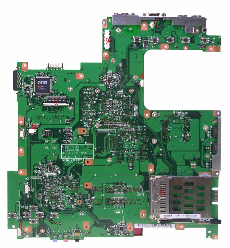
Jumper and Connector Locations
Top View
Item Description Item Description 1 DC-in Jack 2 USB connector 3 CRT connector 4 RJ11&RJ45 connector
Item Description Item
Description 5 MDC connector 6 MDC board connector 7 Main battery connector 8 ODD connector 9 Mini PCI connector 10 VGA 11 CPU 12 North bridge 13 DIMM slot 14 South bridge 15 HDD connector 16 Line-in jack 17 Microphone-in jack 18 Line-out jack 19 Cardbus controller 20 USB connector 21 LAN controller 22 BIOS ROM
Item Description Item Description 1 Keyboard controller 2 Keyboard connector 3 Lid switch connector 4 System fan connector 5 PCMCIA connector 6 Function keyboard connector 7 Touchpad board connector 8 Speaker connector 9 LCD cable connector