7 minute read
LUBRICATION CHART


:Inspection and addition
:Replacement
A:MP grease
B:Brake fluid (SAE J-1703, DOT-3)
C:Gear oil (SAE 75W-80)
1.Front wheel bearing
2.Brake fluid reservoir tank
3.Differential and drive unit
I. Inspection every 8 hours (daily)
II. Inspection every 250 hours (6 weekly)
III. Inspection every 1000 hours (6 monthly)
IV. Inspection every 2000 hours (annual)
Note:
In case of a hand operating condition, the service interval of 170 hours or 1 month is recommendable.
Periodic Maintenance
INSPECTION METHOD
I:Inspection, repair or replacement if required
M:Measurement, repair or adjustment if required
T:Retightening C: Cleaning L: Lubrication
*:For new vehicle *1: Flaw detector
Front axle damage and deformation of of axle beam in vehicle longitudinal
STEERING SYSTEM Steeringwheel Play and loosenessI effectI
Reservoir tank Leak and fluid levelI
Function, wear, damage, leak and mounting looseness
Note:In case of a hard operation, the service interval of 170 hours or 1 month is recommendabl
In case of a hard operation condition, the service interval of 170 hours or 1 month is recommendable.
Periodic Replacement Of Parts And Lubricants
Drive unit oil
Front wheel bearing grease
Brake fluid
Brake master cylinder rubber parts
Wheel cylinder cup seals
Brake fluid reservoir hose
New Model Features
Development Objectives
While most small tractors are driven by engines, this newly developed model is driven by a battery and is capable of towing a load up to 4,000 kg [8,800 lbs] (CBT4 and CBTY4) and 6,000 kg [13,200 lbs] (CBT6) for 60 minutes to satisfy the growing concern about the environment.
Selling Points
1.Optimum driving position and wide opening for a smooth ingress/egress (CBT4 and 6). The driving position and wide opening that considers frequent ingress/egress (CBTY4).
Minimum turning radius: 1,775 mm [69.9 in] (CBT4 and 6)
3.A large capacity battery can be mounted for a longer, continuous operation.
CBT4: 48V 300AH/6HR battery can be mounted
CBTY4: 48V 250AH/6HR battery can be mounted
CBT6: 48V 400AH/6hr battery can be mounted
Outline Of Major Functions
1.Controller
The main circuit adopts a transistor chopper for smooth acceleration and excellent operability at low speeds with less power consumption.
2.Return-to-neutral function
CBT4•6:
The vehicle does not move when the key switch is turned to the ON position while the direction lever is in its forward or reverse position or the accelerator pedal is being depressed.
In such a case, first set the direction lever to the neutral position and release the accelerator pedal, and operate the direction lever and accelerator pedal to move the vehicle.
CBTY4:
The vehicle does not move when the key switch is turned to the ON position while the accelerator lever is in its forward or reverse position.
In such a case, first set the accelerator lever to its neutral position and operate the accelerator lever to move the vehicle.
3.Seat switch (optional for CBT4•6)
•The driving circuit is automatically disconnected when no operator is on the operator's seat even when the key switch is in the ON position. The vehicle does not move if the accelerator pedal is erroneously depressed when getting into /out of the vehicle.
•The head and tail lamps automatically go out when the operator leaves the operator's seat without turning these lamps off.
•In addition to the standard return-to-neutral function, this function prevents the vehicle from moving while the operator is on the operator’s seat with the direction lever in its forward or reverse position or the accelerator pedal being depressed. In such a case, first set the direction lever to the neutral position and release the accelerator pedal, and operate the direction lever and accelerator pedal to move the vehicle
•The hour meter interlocked with the seat switch operates when the key switch is turned to the ON position while the operator is on the operatorÅfs seat. (Optional)
4.Floor switch (optional for CBTY4)
•The driving circuit is automatically disconnected when the floor switch is not depressed. The vehicle does not move if the operator erroneously depresses the accelerator pedal when getting into/out of the vehicle.
•The headlamp and taillight automatically go off when the operator leaves the operatorÅfs seat without turning these lamps off.
•In addition to the standard return-to-neutral function, the vehicle does not move when the floor switch is depressed with the accelerator lever in its forward or reverse position. In such a case, first set the accelerator lever to its neutral position and operate the accelerator lever to move the vehicle.
•The hour meter interlocked with the floor switch operates when the key switch is turned to the ON position while the operator is depressing the floor switch. (Optional)
5.Floor switch pedal (CBTY4: USA)
•The drive motor circuit switch is built in the floor switch pedal. To drive the vehicle, turn the key switch to ON, depress the floor switch pedal and operate the accelerator lever. If the floor switch pedal is released while driving, the drive motor circuit is cut off.
6.Floor parking pedal (CBTY4: EEC)
•The drive motor circuit switch and parking brake operating mechanism are built in the floor parking pedal. When the floor parking pedal is not depressed, the drive motor circuit is cut off and the parking brake becomes effective. To drive the vehicle, turn the key switch to ON and depress the floor parking pedal.
Performances
1.Working hours
*: The continuous working hours are based on Toyota's standard towing operation pattern in the premises.
2.Towing weight (60-min. rating)
3.Traveling performance
* : The towing weight of CBT4 and CBTY4 are 2,000 kg [4,400 lbs] and that of CBT 6 is 3,000 kg [6,600 lbs] when loaded. The gradability of CBT4 and CBTY4 is 5-minute rating and that of CBT6 is 3-minnute rating.
Vehicle Specifications
Vehicle exterior views
Main Specifications
* :Computed values
*1:Towing weight w/ loadCBT4,CBTY4:2000 kg [4400lbs]
*2:Computed values.
CBT6:3000 kg [6600lbs]
*3:CBT4 and CBTY4 are 5-minute rating and CBT6 is 3-minute rating.
Battery Compartment And Required Weight
When the battery is to be purchased locally, always adjust the weight to satisfy the minimum required weight as shown in the table below.
*818 mm (32.20 in) for Europe models.
Service Standard
Troubleshooting
Plate corrosion
End of life
Battery Charge Indicator
The battery charged condition is indicated in ten levels. The upper most LED comes on when fully charged, and the LED moves downward as the battery is discharged. The second lamp from the bottom comes on when about 80 % is discharged. Charge the battery then. If 90 % is discharged, the bottom LED and the second LED from the bottom blinks alternately.
Defective electrolyte
Damaged separator
SulfationPlate warpage and ative substance freeing
Improper charging
Short circuit between cells
Insufficient electrolyte
Overdischarge
Improper water supply
Deposition of freed active substance at bottom of cell
Long storage without operation
Defect of electrolyte
Repeated overdischarge/ overcharge
Excessive charging current
Excessive ambient temperature
Crack or chipping of cell
Overcharge
Fouled terminal or connecting plug
Imperfect terminal connection
Short circuitElectrolyte leakage and reductionLoosened or corroded connection
Battery Assy
Removal•Installation
CBT4•CBT6
Removal Procedure
1Disconnect the battery plug.
2Open the battery hood.
3Remove the battery ASSY. [Point 1]
Installation Procedure
The installation procedure is the reverse of the removal procedure.
Point operation
[Point 1]
Removal•Installation: SST 25009-13201-71
Removal Procedure
1Disconnect the battery plug.
2Connect the battery carrier (OPT) to the vehicle.
3Release the battery stopper.
4Remove the battery ASSY. [Point 1]
Installation Procedure
The installation procedure is the reverse of the removal procedure.
Point operation [Point 1]
Removal•Installation: SST 25009-13201-71
Caution: Securely lock the battery carrier wheels for removal and installation.
Inspection
1.Electrolyte level inspection
Open the cap, and if the white line on the red float has dropped, water should be added. Add water until the white line appears. Stop water addition when the white line appears, since addition is excessive when the tip end of the float comes into contact with the stopper.
As a level gauge is provided at the front of the battery case, the electrolyte level can generally be checked at a glance, but open the cap to check the level when making a periodic inspection.
The green light of the level gauge lights up to indicate activation of the level gauge sensor, and the red light flashes to indicate the necessity of adding water.
Red lightGreen lignt
Note:
Never change the installation location of the sensor.
Reference:
The consumption of electrolyte can be calculated by the following equation:
Consumption (cc) = 5 hour capacity × 0.0336 × number of cells × number of charges
2.Electrolyte inspection
Battery electrolyte is normal when it is transparent. Check turbidity when inspecting the specific gravity. If it cannot be checked clearly, put the electrolyte in a beaker for inspection.
3.Battery electrolyte specific gravity inspection
Use a hydrometer to measure the specific gravity of the electrolyte. Specific gravity upon complete charging:
1.280 [20°C (68°F)] (Reference)
Specific gravity upon end of discharge:
1.150 [20°C (68°F)] (Reference)
The specific gravity of the electrolyte is expressed with that at 20°C (68°F) as the standard.
Equation for converting specific gravity
S20=St+0.0007
(t-20)
S20: Specific gravity at 20°C
St : Specific gravity at t °C tS : Electrolyte temperature upon measurement (°C)
* How to use the hydrometer
(1)Insert the nozzle of the hydrometer into the electrolyte port and allow the electrolyte to be sucked into its outer tube.
(2)Let the hydrometer float correctly without contact with the outer tube, top or bottom, and read the scale at the highest point of the electrolyte surface as illustrated at left when the bubbles in the electrolyte disappear.
(3)After the measurement, wash the inside and outside of the hydrometer well with clear water and store it after wiping water off with clean cloth.
4.Insulation resistance inspection
Measure the resistance between the battery and battery case with an insulation resistance meter (megohmmeter).
Insulation resistance .... 1 MΩ or more
Note:
•When the insulation resistance is less than 1 MΩ, wash the battery with water after removing it from the vehicle.
•Fully dry the washed battery and measure the insulation resistance again. Install the battery on the vehicle after confirming that the insulation resistance is 1 MΩ or more.
Prepare a control table for each battery to record and maintain the inspection results.
Crimping method
Crimping tool Pad
(To prevent the contact piece from bending)
Replacing Battery Plug Terminal
1.Disconnect battery plug cable one by one.
Caution:
Never disconnect more than one cable at the same time. Fatal accident may result by short circuit.
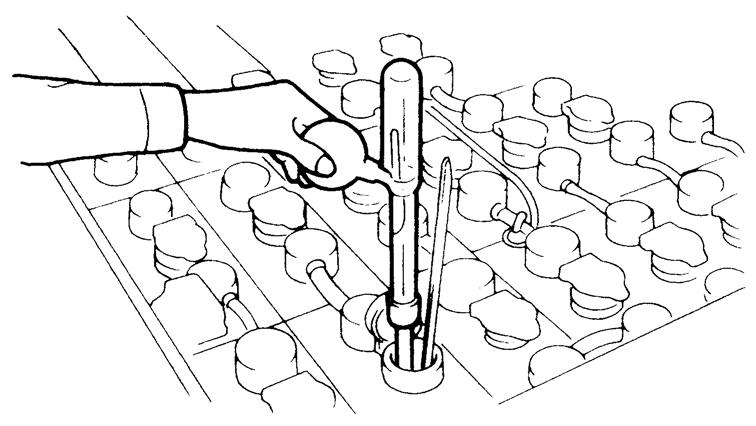
2.Insert a screwdriver from the terminal side, push down the spring at the bottom of the terminal and pull the cable to draw out the terminal.
3.Strip the tip of the cable for Approx. 30 mm, solder sufficiently and insert it to the contact portion of the new terminal.
Note: Be sure to prevent solder from pouring out and adhere to the contact surface of the terminal.
4.When crimping cables, never bend the terminal with a crimping tool.
5.Insert the terminal to the battery plug. Check that the tip of the terminal goes over the tip of the spring and securely set in the position.
BATTERY TRAY (CBTY4)
Removal•Installation
Removal Procedure
1Disconnect the battery plug.
2Remove the battery ASSY. (See page 1-6.)
3Remove the battery tray.
Installation Procedure
The installation procedure is the reverse of the removal procedure.
Note:
In order to remove the battery tray, first remove the set bolts, draw out 1/3 of the tray, and hoist with a hoist crane.