53 minute read
TOYOTA Master Service Manual Product family OL

Part number: 168570-040
Issued: 1999-01-02
1. Document list
Introduction to BT’s Service Manual
This Service manual contains product information regarding the current trucks including the technical data and instructions for maintenance and service. It includes the operator’s Instruction Manual, Spare Part Handbook and oil and grease specifications:
MMachine information
PPreventive maintenance
SService instructions
OOptions
At the top of each page you can find information on which section the page belongs: Section M4 means that it is Technical Data; F-code means it deals with this specific truck family; T-code means specific products; Date and Version number give information on when the page was issued and which version.
It is our ambition to send modification notifications concerning improvements to you as soon as possible. It’s stated on the notifications which section/s in the binder should be replaced. Notifications should be inserted immediately so that the binder always contains current service information.
When contacting BT’s technical support always have the actual Service Manual close at hand. If you have any views regarding the Service Manual, please contact your training officer at BT who will forward your views to the technical documentation department.
This document can be available on different media and will have different part numbers. Please see the following example:
XXXXXX-040=An English document on paper
XXXXXX-04C=The same document but on CD-ROM
Operator’s manual
Operator’s manual
Valid from serial number:
1. General
An Operator´s Manual is supplied with every truck. In the table below, you can see which Operator´s Manuals are available for this machine series.
1.1. Issued operator’s manuals
In this Master Service Manual can be found a typical Operator´s Manual for the machine series. We have chosen this for your own safety when working with the truck.
General product information
Valid from serial number:
1. Presentation of the truck
The truck is an order picking truck for picking goods or products from the ground floor or first shelf. The truck is equipped with a tiller arm for optional operation, either standing in the driver’s compartment or walking by the side of the truck. The speed is reduced to a suitable walking speed when the truck is operated walking at side.
The truck has a maximum lifting capacity of 1500 kg.
The truck has a 24 V electrical system and the speed is regulated by means of a transistor controller to provide gentle control of acceleration and speed while driving.
The truck is available in two designs with different maximum speeds, 6 km/h (1.6 m/s) or 8 km/h (2.2 m/s). The maximum speed of the truck is variable so that the speed can be adapted according to the local operating conditions.
The forks are lifted by using a powerful and compact hydraulic unit that is automatically shut-off when the forks reach their highest lifting position. The automatic shut-off is used to increase the service life of the hydraulic components and reduce the power consumption from the battery.
Note that some of the truck models described in the Operator’s Manual may not be marketed in your country.
2. Intended application of the truck
The truck is solely designed and manufactured to handle indoor order picking. The truck should be fitted with the appropriate accessories relevant to the application.
3. Forbidden application of the truck
The truck is designed for indoor order picking. It is not permitted to use the trucks for other purposes including the following:
-In areas that contain dust or gases which can cause fires or explosions
-As a tow-truck for trailers
-To tow other trucks
-To transport/lift passengers
-To drive on gravel or grass
4. Truck data
The table provides information regarding some technical data, which is of value with daily use of the truck.
Truck typePMO 15
Rated capacity, kg *1500
Lift height, mm205
Platform height, highest/lowest, mm220/100
Operating speed without load, m/s1.6/2.2
Operating speed with rated load, m/s1.4/1.8
Max. operating gradient with rated load, %8
Weight without battery, kg (Ah)425 (240) 440 (320)
Weight with battery, kg (Ah)645 (240) 685 (320)
Turning radius with raised forks (Wa), mm (Ah) 1850 (240) 1898 (320)
Continuous noise level according to CE prEN 12053, dB (A)< 70
Full body vibration value according to document N47E CEN/TC150/WG8, m/s2 0.61
Permitted drive wheel, materialVulkollan
Vulkollan sajpat
Tractothan Elastomer
* Deviations may occur on trucks adapted to specific application; the correct value can be found on the trucks’s type plate. In such cases the truck is also fitted with a modification plate.
5. Truck dimensions
The illustration shows external dimensions for the truck in its standard design.
6. Identification plate
The illustration shows the identification plate used on the truck.
ItemTextUnit
AMODEL BNO
CRATED CAPACITYkg
DWEIGHT WITHOUT BATTERYkg
EBATTERY WEIGHTMAX MIN kg kg
FBATTERY VOLTAGEV
7. Modification plate
The picture shows the modification plate which is found on the truck if it is supplied as non-standard or if it has been modified after leaving the manufacturer. The plate includes information according to the table below.
ItemText
AModification plate
BType
CSerial number
DPlace of manufacture
EPlace of manufacture
FModification number
GDate
8. Main components
1.Identification plate: With model designation, serial number, year of manufacture, weight without battery, battery weight, rated capacity, battery voltage and manufacturer.
2.Tiller arm:
The truck can be manoeuvred by the operator either standing in the driver’s compartment or walking by the side of the truck. The brakes are applied in the tiller arm’s upper and lower positions.
3.Emergency switch off
4.Cover:
Removable which provides good accessibility when servicing.
5.Battery/Recharging connector: The battery is charged via the permanently fitted charging connector.
6.Hydraulic unit: Pump motor, pump, valves and oil tank integrated in a compact unit.
7.Drive unit with brake: Drive motor, gears and drive wheel integrated in a compact unit. Steering bearings between the motor and gears.
8.Serial number: The serial number plate fitted to the chassis.
9.Castor: Spring-loaded swivel castor to ensure stability.
10.Electric panel:
The electrical components are collected on one panel. 24 volt electrical supply. The speed is variably controlled by means of a transistor.
11.Fork carriage:
The forks are held horizontal by a link system. The fork carriage requires no lubrication.
12.Battery: 24 V.
13.Lifting points: For the machine weight, see the identification plate.
9. Warning and information plates and symbols
The figure shows the position and significance of the plates and symbols located on the truck.
Technical service data
Valid from serial number:
593PMO 153358887AT-
MODELLPMO 15
Drive motor
TypeTTL 140S-M2
Power, kW1,2
Intermittens, %60
Min carbon brush length, mm12
Min commutator diameter, mm47
Transmission/gear
Type2-step angular
Gear ratio19.14:1
Oil volume, liter1,0
Oil typeHypoid oil
Normal temperatureSAE 80W/90 < -15oCSAE 75W
Wheels
Drive wheel, mmDia 215x70
Axle pressure without load, kg355
Axle pressure with rated load, kg415
Torque wheel screws, Nm65 Nm
Fork wheel, mmDia 85
Axle pressure without load, kg180
Axle pressure with rated load, kg1620
Support wheel, mmDia 125x40
Axle pressure without load, kg2x95
Axle pressure with rated load, kg2x95
Modellpmo 15
Hydraulic unit Power, kW2
Revolutions/min at work pressure3000
Intermittens, %10
Min carbon brush length, mm12
Min commutator diameter, mm4.75
Pressure at rated load,bar150
Relief pressure, bar175
Pump flow, litre/min5
Tankvolume, litre1,0
Oil typeHypoid oil
Normal temperatureISO-L-HM32
< -15oCISO-L-HV32
Fuses
Motor circuits, A100 Control circuit, A7,5
Batteries
Dimension WxLxH, mm196x645x570/ 245x645x570
Capacity, Ah240/320
Weight, kg200/250
MODELLPMO 15
Lifting/lowering time
Lift without load, s1,7
Lift with rated load, s2,3
Lower without load, s2,2
Lower with rated load, s1,9
Current consumption
Driving without load, A35
Driving with rated load, A46
Lifting without load, A55
Lifting with rated load, A104
1. Issued Quality Parts
Introduction, maintenance
All points in the service program should be carried out to attain the highest safety and the least possible downtime. The service intervals are only a guide and do not need to be followed to the letter. The operator may adapt them to local conditions, but it is important that the intervals comply with the minimum requirements.
The service intervals are based on the running times and can be adapted to most normal 8 hour shifts. The service interval may be shortened if the truck is used more frequently or in more demanding situations, e.g cold store, dusty or corrosive situations. The following running times have been used when calculating the intervals:
-Day time:08.00-17.00 (20 hr./week)
-2-shifts:06.00-14.00, 14.00-22.00 (40 hr./week)
-3-shifts:06.00-14.00, 14.00-22.00,22.00-06.00 (60 hr./week)
Ensure the truck is given a regular maintenance service after every 500 driving hours. The truck’s safety, efficiency and service life is dependent on the service and maintenance it is given.
Only use approved spare parts when service and repair work are carried out.
1. Safety regulations with maintenance work
Only personnel that have been trained in the service and repair of this type of truck are authorised to carry out service and repair work.
•Do not carry out any maintenance work on the truck unless you have the correct training and knowledge to do so
•Keep the area where you carry out the service clean. Oil or water makes the floor slippery
•Never wear loose objects or jewellery when working on the truck
WARNING!
Short-circuiting/Burns. When working with the truck’s electrical system, shortcircuiting/burns can occur if a metal object comes into contact with live electrical connections. Remove watches, rings or other types of metal jewellery.
•Always disconnect the battery by pulling out the battery isolator when carrying out maintenance work on the truck unless otherwise stated in this Service Manual
•Always switch off the truck’s power supply before opening the covers on the drive unit or electrical system
•Relieve the system pressure slowly before starting work on the truck’s hydraulic system
•Use paper or a rigid sheet of cardboard when checking for oil leakage. Never use your hand
•Bear in mind that the oil in the transmission or the hydraulic system can be hot
WARNING! Risk of burns. Hot transmission and hydraulic oil. Let the truck cool before changing the oil.
•Only fill the hydraulic system with new and clean oil
WARNING!
The hydraulic system can be damaged. If the oil is contaminated hydraulic components can be damaged. Always use new and clean oil in the hydraulic system.
•Store and dispose of changed oil in accordance with local directives
•Do not release solvents and the like, which are used for cleaning/washing, into drains that are not intended for this purpose. Follow the local directives that apply for disposal
•Disconnect the battery when welding on the truck
NOTE!
The battery can be damaged. When welding using an electric power source the welding current can enter the battery. The battery should therefore be disconnected.
•Remove at least 100 mm of paint around the welding/ grinding area through sand-blasting or the use of a paint stripper when welding or grinding on painted surfaces
CAUTION!
Harmful gases. Paint that is heated gives off harmful gases. Remove 100 mm of paint from the work area.
2. Cleaning and washing
Cleaning and washing of the truck is important to ensure the truck’s reliability.
•Carry out general cleaning and washing weekly NOTE!
Risk of short-circuiting. The electrical system can be damaged Disconnect the battery before washing by pulling out the battery connector.
2.1. External cleaning
•Remove rubbish, etc. from the wheels daily
•Use a well-known degreasing agent, diluted to a suitable concentration
•Rinse off loose grime using tepid water NOTE!
Jamming, corrosion. Mechanical components can be damaged. After washing, the truck should be lubricated as set out in the chapter Maintenance and lubrication chart.
2.2. Cleaning the motor compartment
•Cover the electric motors, connections and valves before washing NOTE!
Risk of short-circuiting. The electrical system can be damaged. Electrical components must not be cleaned with a high pressure washing unit.
•Clean the motor compartment using a well-known degreasing agent, diluted to a suitable concentration
•Rinse off loose grime using tepid water
2.3. Electrical components
•Blow electric motors down using compressed air
•Clean the electrical panels, electronic boards, contactors, connections, solenoid valves, etc. using a damp cloth and a cleaning agent
NOTE!
Risk of short-circuiting. Electrical components can be damaged. Do not break the guarantee seal on the electronic board.
3. Safe lifting
All lifting must be carried out on a flat, non-slip and firm surface. Avoid new laid asphalt or asphalt on a hot summer’s day.
•Activate the parking brake to prevent the truck from moving during the lift. If the lift applies to the brake wheel, chock the other wheels so that the truck stands still
•Select a lifting point so that the lift is as easy as possible (one corner at a time). If the truck has marked lifting points on the under side of the chassis these can be used to obtain a well balanced lift
•Ensure that the surface under the jack is clean and free from oil and grease
•Ensure that your hands and the jack’s lever are free from oil and grease
•Use the lever that belongs to the jack. A lever that is too short requires more force than is necessary. If the lever is too long there is a risk of the jack being overloaded
•Support the truck:
-as close as possible to the part of the chassis that is to be lifted. This reduces the risk of the truck tipping over -so that the truck cannot roll
• Never lift up the jack in order to lift higher
• Never work under a lifted truck unless it is well supported
WARNING!
Risk of crushing. A badly supported truck can fall. Never work under a truck that is not supported on trestleblocks and secured by a lifting device.
1.
1.
oil’s and grease for PMO15
BHydraulic OilISO-L-HM32ISO-L-HV32Hydraulic Systems
CTransmission OilHypoid Oil
1. Service instructions
C-code
S 0Chassis0000
S 1Primary motor1000
S 2Transmission/Drive gear2000
S 3Brake/Wheel/Caterpillar system3000
S 4Steering system4000
S 5Electrical system5000
S 6Hydraulic/pneumatic system6000
S 7Working functions, lift mast/cylinders7000
S 8Peripheral/installation equipment8000
S 9Options, attatchments9000
Drive motor
Valid from serial number:
1. General
The drive motor, drive gearbox and brake are combined as a complete drive assembly.
The drive motor is a compound type direct current motor, i.e. it is comprised of an stator winding connected in series with the armature and an stator winding, called a shunt field, which is connected in parallel with the armature.
The armature current is fed by four traditional type carbon brushes which lie against the armature commutator.
The rotation direction of the motor is changed by changing the armature current flow direction with relation to the stator windings.
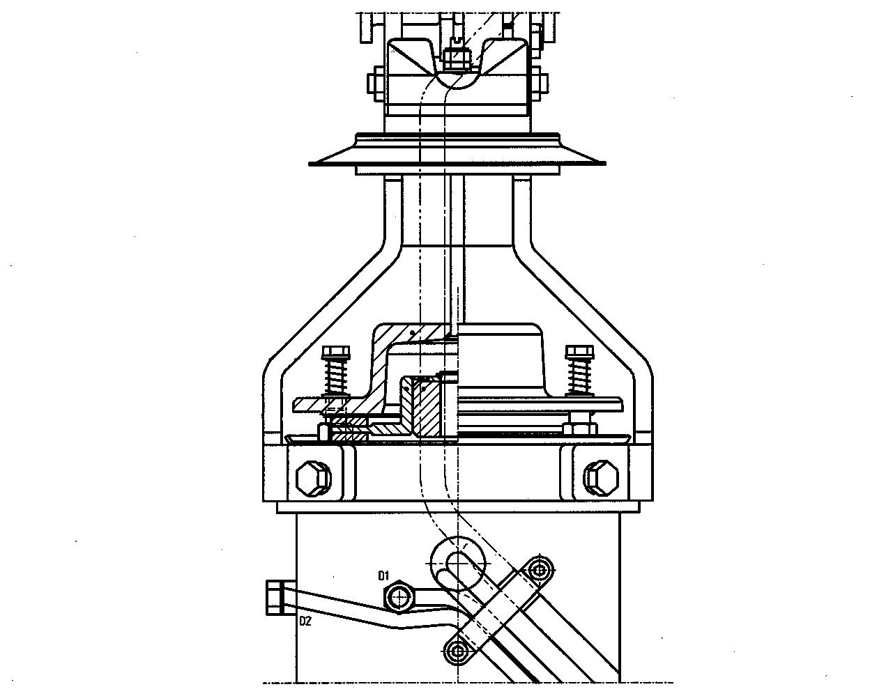
In the illustration below, A1 and A2 are the armature connections, D1 and D2 are the series field connections and E1and E2 are the shunt field connections. The motor rotation direction is changed by reversing armature connections A1 and A2.
1.1. Mechanical construction
The motor is comprised of a yoke into which the field windings are mounted. At each end of the yoke there is a bearing end bracket in which the armature bearings are mounted.
A brush bridge assembly with four spring loaded carbon brushes is mounted on the bearing box at the motor commutator end. The carbon brushes sit against the armature commutator and transfer the armature current to armature windings.
Each of the motor windings is accessible via external connections.
1.2. Special tools
Tool
Torque wrench>30Nm
Undercut cleaner60°, R=0.2 mm, D=0.6 mm
2. Removal/Refitting
2.1. Removing the motor from the truck
•Open the motor compartment covers and remove the battery cable shoe.
•Remove the motor cables (armature winding, series field winding and shunt field winding) and the tiller arm cable from the electrical panel. Remove any cable ties.
•Remove the cover over the tiller arm. Disconnect the tiller arm cable from the tiller arm and brake microswitch and remove the tiller arm from the bracket.
•Remove the motor attachment bracket from the chassis (four bolts).
•Lift the truck straight up with the drive wheel resting on the floor. Check carefully that the drive assembly does not follow up with the truck or fall to the side.
The necessary service and repairs can now be carried out on the motor.
2.2. Re-assembly
•Lift the motor carefully down into the drive gearbox. The four studs on the motor must fit into the corresponding holes on the drive gearbox. In order for the motor to fit fully into the drive gearbox upper surface, the drive gearbox must sometimes be rotated by hand so that the motor shaft gear engages with the drive gearbox gear. Care must be taken that the motor O ring seal is not damaged.
•Tighten the nuts on the studs to the prescribed torque, 26.6 Nm.
•Install the brake unit and adjust as per the instructions.
•Replace the drive assembly in the truck and re-connect the motor cables. Check that the polarity is correct.
•After the completed re-assembly, the brake function must be tested before the truck is moved.
3. Service/Repairs
3.1. Cleaning
For correct functioning, it is important that the motor is kept as clean as possible. The motor and motor compartment must be regularly checked for dust, oil and other contamination.
If the motor windings and interior is dry, use a vacuum cleaner with suitable mouthpiece to clean the motor. Compressed air can be used in combination with a vacuum cleaner. In this case the compressed air must be clean and dry.
If the windings have a coating, use a lint-free cloth. The cloth can be dampened with an organic and volatile cleaning agent if necessary, that can dissolve grease and which will not damage the windings. The cleaning agent must not be used in such quantity that it can enter the motor.
Remains of cleaning agent must be removed with a suitable solvent if an oily surface is left.
If the motor parts are badly dirtied it can be necessary to spray them with a solvent. It is especially important for the armature that the solvent is applied in such a way that dissolved dirt does not enter into the motor section.
One method of cleaning the armature is to dip it in solvent. If this is done the armature must always be heat dried. Good ventilation is necessary during drying and it must continue until a number of insulation measurements give similar and approved results.
3.2. Removal of motor
•Tie up the complete drive assembly so that the motor shaft is vertical.
•Remove the tiller arm bracket from the motor by first loosening the brake adjustment screw and then the four bracket bolts.
•Remove the brake unit from the motor commutator end.
•Remove the four nuts for motor attachment to the drive gearbox and lift the motor carefully straight up, without damaging the sealing surfaces to the drive gearbox.
•Protect the drive gearbox from contamination by placing a suitable cover over the opening, for example, a piece of plastic.
•Remove the four plugs that cover the carbon brushes, lift the springs to one side and lift up the carbon brushes.
•Remove the brake disk collar by first removing the circlip and washer at the end of the armature shaft. The collar can then be lifted off. It may need to be pulled off with a suitable tool.
•Dismantle the bearing bracket (11) at the commutator end together with the brush holder (03) and carbon brushes (02) by removing the six hexagon socket bolts. Next, lay the motor with a fixed stop against the edge of the bearing shield. Strike the end of the armature shaft carefully with a rubber mallet.
•Remove the bearing shield (25) on the drive end together with the armature (09). Be careful not to damage the motor windings when the armature is removed from the motor yoke.
•Remove the gear wheel on the armature drive end. This is done by removing the gear wheel nut. Pull off the gear wheel with the aid of an puller. Note that the gear wheel is locked with Loctite onto the armature shaft.
•Remove the inner circlip and washer under it. Pull the armature shaft out of the bearing (24).
•Remove the outer circlip and washer and remove the bearing from the bearing shield.
•Remove the bearing shield seal (26) and clean the bearing shield carefully.
•Install a new seal in the bearing bracket.
3.3. Refitting of motor
•Reassemble the motor in the reverse order to dismantling. Check carefully that the armature can move freely in the rotation direction and that the carbon brushes are lying against the commutator.
•Check the insulation resistance of the motor (between respective windings and the motor yoke). For a new motor this must be between 2 and –3 Mohm. A used motor has been subjected to contamination and in this case a resistance of down to approx. 1 Mohm can be acceptable.
•Install a new O ring in the drive shaft end bearing shield and a new seal in the bearing shield collar.
3.4. Armature bearings
The armature bearings are comprised of a permanently lubricated and double sealed bearing, type 6204-2Z/C3 in the armature commutator end and a single sealed 6205/2Z-C3 bearing in the armature drive end.
The grease used in both bearings is high temperature type HT24.
The bearing open spaces are partially filled with Texaco SRi2 grease from the factory to protect the inside of the bearing against the penetration of dust and contamination.
The life of the bearing is between 5000 and 20 000 hours, depending upon the speeds and other stresses it has been subjected to.
During heavy loading the bearing temperature can rise to 180°. An abnormal temperature increase, or excessive noise, indicates insufficient lubrication or bearing wear.
3.4.1. Changing the drive end bearing
Clean the new bearing and fill to max. 50% with grease, type HT24. Install the bearing in the bearing shield with the unsealed side in toward the shield. Put the washer between the circlip and bearing in place and lock the bearing with the outer circlip.
Install the armature in the bearing shield and lock it in place with the washer and circlip.
Remove all grease and other contamination from the armature shaft gear wheel cone. The same applies for the gear wheel inner surface.
Apply a film of Loctite 603 onto the armature shaft cone and install the gear wheel onto the shaft. Put the washer in place, apply a film of Loctite 243 onto the shaft threads and screw on the nut. The nut must be tightened to the prescribed torque, 30 Nm, and then locked with a centre punch.
During refitting of the armature and bearing shield, care must be taken not to damage the field and armature windings.
3.4.2. Changing the commutator end bearing
After the commutator end bearing shield has been removed, the bearing can be removed from the armature shaft with a suitable extractor.
The new bearing is installed onto the armature shaft with the aid of a brass drift.
3.5. Carbon brushes and brush holder
The following checks must be carried out during the service and repair of the motor:
•The brush bridge and brush holder must be firmly attached.
•The carbon brushes must move freely in their holders.
•The brush holders must be free from contamination.
•Worn brushes must be replaced. The minimum permissible length of the carbon brushes is 11 mm.
The carbon brushes are normally supplied with a preformed radius that corresponds to the commutator radius.
3.5.1. Changing carbon brushes
Carbon brushes can be replaced without the drive unit needing to be removed from the truck.
To change the four carbon brushes, the plastic plugs that cover the brushes in the motor yoke must be removed. Then remove the screw that holds the cable for the brush in question. When the cable has been disconnected, lift the spring to one side so that the carbon brush can be withdrawn from the holder.
Refitting is carried out by installing a new carbon brush into the holder, lifting back the spring and then reconnecting the carbon brush connection cable.
After fitting, check carefully that the carbon brush can move freely in the holder and that it is lying correctly against the commutator.
3.6. Commutator
The commutator should normally have an even colour over the whole surface. The appearance of the commutator can, however, vary quite considerably, depending on how it has been used. If the commutator shows burn marks or uneven black coloured areas, it must be cleaned with fine glass paper. Emery cloth must never be used.
3.6.1. Turning the commutator
If it should become necessary to machine the commutator in a lathe, this must be done accurately and carefully.
To achieve an acceptable result the cutting speed must be at least 200 m/min if a hard metal tool is used. If a diamond cutting tool is used, which will produce the best results, the cutting speed must be considerably higher.
Feed must be between 0.08 - 0.1 mm and cutting depth must not exceed 0.05 mm.
After machining, the commutator eccentricity must not exceed 0.02 mm and surface unevenness must be less than 4 µm. An eccentricity of max. 0.04 mm can be accepted in use.
The commutator design allows machining a number of times. The diameter must not, however, be less than 60 mm.
It is normal for machining to be carried out for each third carbon brush replacement.
After each machining, the Micanite between the segments must be undercut down to a depth of 0.6 mm with a special tool. Micanite remains must not be left on the sides of the segments. After machining and undercutting of the Micanite, the segment edges must be chamfered. When this work has been completed, the space between the segments and the segment sides must be as shown in the illustration below.
4. Storage/Transport
If a motor is to be stored for a longer period, for example, more than a month, it must be packed so that it will not be damaged during storage.
The motor components that can be damaged if the motor is not stored correctly are the carbon brushes, commutator and bearings. The motor can be damaged by:
•Dust and other contamination.
•Moisture and condensation if the motor is stored in a location with large temperature variations.
•Rust, especially if the motor is stored in a location with corrosive gases.
•Mechanical influences such as vibration.
4.1. Storage
The following actions are recommended for storage:
•Lift all four carbon brushes.
•Wrap the armature in paper or other protective material.
•Store the motor as an assembled unit.
•Wrap the motor in dust and moisture protective material.
•Avoid placing the motor where it can be subjected to vibration.
The motor must be stored in a room with even temperature. Condensation in the windings can be avoided by keeping the winding temperature a few degrees higher than the surrounding temperature.
Oxidation, especially on the commutator, can appear even under normal storage conditions. These problems increase if the air contains corrosive gases. These problems are especially prevalent if sulphur dioxide (SO2), chlorine (Cl2) and ammoniac (NH3) exists.
Vibration causes damage to the motor bearings. This can be avoided if the armature is rotated a few turns each month.
Check that the motor shaft ends and other clean metal surfaces are covered with a film of rust protective oil.
1.1. Technical data
DataDescription
Oil changeFirst time: 250 hours Regular change: 3000 hours
1.2. Gear components
Pos NoComponent
11Drive shaft
12Drive shaft seal
ABuilt-in measure, pinion height65 mm
1.3. Special tools
Pos NoTool
1Bearing withdrawer: part no = 08-13022
2Dial indicator with magnetic bracket
3Thickness gauge
4Micrometer 0-25 mm (0-1 inch)
5Spring balance 0-10 kg (0-22 lb)
6Measuring gauge: part no = 06-13020
7Assembly axle: part no 08-13021
2. Removing the gear from the truck
•Lift the machine so the bolts for the driving gear are easily accessible from beneath. The truck can also be laid on the side after removal of the battery and sealing off the hydraulic system.
•Remove the drive wheel (17 mm spanner)
•Drain the gear oil by removing the lower gear cover (6mm allen key).
•Remove the nuts (13 mm spanner) holding the gear and motor together.
•Take the driving gear out of the machine.
3. Change of seal on the drive shaft
•Remove the gear from the truck as shown in chapter ”Removing the gear from the truck”.
•Remove the upper gear cover (6 mm allen key).
•Knock out the locking on the drive shaft nut.
•Remove the drive shaft nut (36 mm spanner).
•Knock the drive shaft out with a plastic club or press it out.
•Remove the crown wheel and bearing L3.
•Remove the old seal ring and re-fit with a new part.
•Put the drive shaft in position and place the inner ring of the bearing L3 in the gear housing.
•Put the crown wheel onto the splines of the drive shaft and fit a new washer and nut. Tighten the drive shaft nut 300Nm (217 ft-lb) with a torque wrench.
•Lock the shaft nut with a punch into the groove in the shaft.
•Fit the covers to the gear with new gaskets. Tightening torque: 26,6Nm (19,5 ft-lb).
•Fit the driving gear into the truck. Tightening torque: 26,6Nm (19,5 ft-lb). Fill up with new oil.
•Fit the drive wheel. Tightening torque: 65Nm (47,7 ft-lb).
4. Reconditioning of the gear
•Remove the gear from the truck as shown in chapter ”Removing the gear from the truck”.
•Remove the gear covers (6 mm allen key).
•Knock out the locking on the drive shaft nut.
•Remove the drive shaft nut (36 mm spanner).
•Knock the drive shaft out with a plastic club or press it out.
•Remove the crown wheel and bearing L3.
•Remove the old seal ring.
•Press or knock out the bearing cups for bearing L3 and L4 and remove the shim-pack S3 from the gear housing.
•Remove the bearing L4 from the drive shaft by using the withdrawer, part no 08-13022. Remove the shim S4 from the shaft.
•Knock out the locking on the pinion nut. Remove the nut (22 mm spanner) and the primary gear wheel.
•Knock out the pinion with a plastic club or press it out. Remove the bearing L2 and shim S2.
•Remove the bearing L1 from the pinion with the withdrawer, part no 08-13022.
•Press or knock the cups for the bearings L1 and L2 out and remove the shim-pack S1 from the housing.
•Clean the covers, gear housing and drive shaft with a suitable dissolvent.
•Fit new races for the bearings L1 and L2 into the gear housing with 0,5mm shim S1.
•Fit the new bearing L1 on the new pinion.
•Assemble the pinion, bearing L2 and primary gear wheel. Assemble with enough thickness of shim S2 so that there is no axial play. Tighten the nut 30Nm (22,5 ft-lb), using the old nut.
•Fit the new races for the bearings L3 and L4 into the gear housing without shim S3.
•Fit the assembly axle 08-13021 with the bearing L4 into the gear housing. Place the bearing L3 and the crown wheel onto the axle. Make sure that there is enough shim S4 for the bearing L4 so there is no axial play on tool 08-13021. Tighten the axle nut 100Nm (72 ft-lb), using the old nut.
•Measure the pinion height with the measuring gauge, part no 08-13020, between the surface of bearing L1 and the pin on tool 08-13021. Use shims or feeler gauge together with the measuring gauge to get the correct thickness of shim S1. Built-in measure pinion height = 65 mm, measuring gauge length 59 mm + the radius of the pin 5 mm + 1mm shim or feeler gauge thickness. The difference from 65 mm gives you the thickness of shim S1.
•Assemble the pinion, bearings and primary gear wheel with shim thickness S2 so that there is no axial play on the pinion, Zero-play, when having tightened the pinion nut 70Nm (50,5 ft-lb). When needed adjust S2 so that the play is zero.
•Fit the assembly axle 08-13021 with bearings, crown wheel and shim as previously. Tighten the nut 300Nm (217 ft-lb)
•Measure the flank clearence with the crown wheel in three different positions. Carefully point the dial indicator 90degrees to the gear tooth surface.
•Shim (S3) bearing L3 so that a flank clearence of 0,10–0,15mm is attained. Remove the same shim thickness from S4 that is fitted on S3, before the tool with bearings and crown wheel is reassembled.
•Check the flank clearence and measure the axial play on the tool 08-13021.
•Adjust the axial play to Zero-play by adjusting shim S4.
•Check the gear tooth impression with engineer’s blue. Adjust shim S1 when needed. After adjusting S1, S2 will need to be set. S2 needs to be reduced if S1 thickness is increased. But if the thickness of S1 is reduced, then S2 is increased. Check the axial play on the pinion.
•Fit the tool 08-13021 with bearings and crown wheel. Check the flank clearence. Adjust shim S3 when needed. S4 is to be adjusted, reduced if S3 is increased and increased if S3 is reduced, correspondingly to the change on S3. Check the axial play on tool 08-13021.
•Check the gear tooth impression. When the impression is correct fit a new washer and pinion nut. Tighten the nut 70Nm (50,5 ft-lb) and lock it with a punch in the keygroove.
•When the gear tooth impression and the axial play is correctly adjusted, remove tool 08-13021. Shim-pack S4 is shifted over to the drive shaft and bearing L4 is placed on the shaft.
•Fit the new seal ring in the gear housing.
•Put the drive shaft into the housing and put bearing L3 in place.
•Put the crown wheel onto the splines of the drive shaft and fit a new washer and nut. Tighten the drive shaft nut 300Nm (217 ft-lb) with a torque wrench. Check the axial play on the drive shaft, shall be Zero. Lock the nut with a punch in the groove on the shaft.
•Check the force needed to rotate the gear with the spring balance. Maximum value: 6-6,5 kg.
•Fit the covers onto the gear with new gaskets. Tightening torque: 26,6Nm (19,5 ft-lb).
•Fit the driving gear into the truck. Tightening torque: 26,6Nm (19,5 ft-lb). Fill up with new oil.
•Fit the drive wheel. Tightening torque: 65Nm (47,7 ft-lb)
Mechanical brakes
Valid from serial number:
1. General
The brake is a mechanical spring-loaded brake. The brake construction is as shown in the component list below.
PositionDescription
1Brake disk
2Adjustment screws for braking force
3Collar
4Adjustment screws for clearance in off position
5Pressure plate
2. Function
The mechanical brake provides both the driving and parking brakes for the truck.
2.1. Releasing the brakes
The brakes are released when the tiller arm is in the driving position.
2.2. Braking
The truck is braked when the tiller arm is moved into one of the two braking positions.
3. Maintenance
The brakes require virtually no maintenance in normal working environments. It is, however, recommended that regular cleaning, inspection of wear in brake disk and pressure plate plus the clearance between these is carried out in accordance with the schedule for preventative maintenance. Check also the brake force adjustment.

PositionAdjustment measurement
1Clearance in un-braked position
2Adjustment of brake force. Clearance in braked position
1.
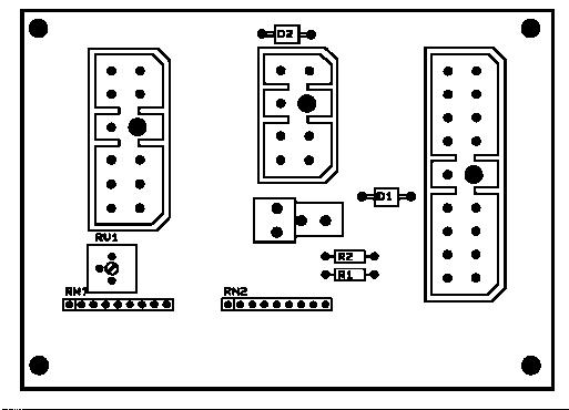
2. Electrical panel, components
3. List of symbols
SymbolDescriptionFunctionRemark
A1Transistor controller
A2Electronic card
BtBattery
F10FuseMotor circuit100 A
F50FuseControl circuit7,5 A
H1Horn
K11ContactorDrive directionFork direction
K13ContactorDrive directionSteer wheel direction
K30ContactorPump motor
M1MotorDriving
M3MotorPump
P1IndicatorHour meter
P3IndicatorBatteryindicator/Hour meter
R1PotentiometerSpeed5 - 0 kOhm
RV1PotentiometerSpeed reduction
S10Switch ”Brake”
S15SwitchDrive directionSteer wheel direction
S16SwitchDrive directionFork direction
S17SwitchKey
S18SwitchHorn
S21SwitchEmergency reverse
S41SwitchFork lowering
S52SwitchFork lift
Y41Magnetic valveFork lowering
3.2. Circuit diagram 2(3)
4. Operating description
4.1. General
The transistor regulator A1 regulates the speed variably up to maximum speed. When the truck is started the regulator checks the closing sequence for the microswitches in the circuit. The regulator is equipped with a LED that displays the system status.
The electrical system has a connection card A2 to group all the connections to the control card for input and output signals to the transistor regulator. The connection card is equipped with LEDs to indicate incoming and outgoing signals and a potentiometer to adjust the maximum speed.

References
For further information on transistor regulation and the connection card, see C-code 5460 and 5710.
4.2. Description
The description is divided into different phases that correspond to the operating sequence stages. The correct LED patterns are shown below for each sequence stage. A filled circle represents the LED when on.
4.3. Ignition lock S17 in the ON position
When S17 closes, the transistor controller will check that S10 is not closed. If this is the case, operation is not permitted.
Battery voltage on A2-terminal 202, LED 202 lights up. A2 (-) return terminal 409. Battery voltage to A1.16 via A2-terminal 410, LED-status starts to flash.
4.4. The operating arm in drive position, S10
When the opersting arm is pushed down to the driving position, S10 is activated and closes and at the same time the brake is mechanically released. Voltage obtained via terminal 109 and 408 to A1.15, LED 109 lights up, on the hour meter terminal 206 and the shunt field terminal 301.
The transistor controller now regulates the current through the shunt field, 1,2 A, (-) return via terminal 302, 417 and A1.1.

4.5. Driving, steer wheel direction
When the butterfly is activated for driving in the fork direction, S15 will close. The transistor controller checks that S10 is closed before S15 closes, if not driving is not permitted.
Battery voltage obtained via terminal 102 and 412 to A1.12, LED 102 lights up. Battery voltage to K13 via terminal 403. A1.3 now gives (-) return to K13, (-)input on terminal 402, LED 402 lights up.
Depending on the position of the speed control(R1) and adjustment of potentiometer RV1 will A1.8 obtaine a voltage between 4.8-0.25 V.
The motor current now passes through F10, the series field D2-D1, K13, the armature A1-A2 and K13 to battery negative via A1.
4.6. Driving, fork direction
When the butterfly is activated for driving in the fork direction, S16 will close. The transistor controller checks that S10 is closed before S16 closes, if not driving is not permitted. Battery voltage obtained via terminal 101 and 411 to A1.11, LED 101 lights up. Battery voltage to K11 via terminal 403. A1.2 now gives (-) return to K11, (-)input on terminal 401, LED 401 lights up.
Depending on the position of the speed control(R1) and adjustment of potentiometer RV1 will A1.8 obtaine a voltage between 4.8-0.25 V.
The motor current now passes through F10, the series field D2-D1, K11, the armature A2-A1 and K11 to battery negative via A1.
4.7. Reversing/motor brake steer wheel direction to fork direction
S15 returns to neutral position while S16 closes. The current in the series fiels causes the motor to work as a generator since the drive wheel rotates in the ”wrong direction”.
The transistor controller detects the generated current at connection A2, and reduces the series field current to 60A.
When the drive wheel rotates in the ”right direction” and the potential at connection A2 becomes positive, acceleration is done according to adjusted values of current limit and acceleration.
During braking sequence, the armature current passes in the circuit A2-A1, K13, A2, the brake diode of the transistor controller, M- and K13.

4.8. Reversing/motor brake fork direction to steer wheel direction
S16 returns to neutral position while S15 closes. The current in the series fiels causes the motor to work as a generator since the drive wheel rotates in the ”wrong direction”.
The transistor controller detects the generated current at connection A2, and reduces the series field current to 60A.

When the drive wheel rotates in the ”right direction” and the potential at connection A2 becomes positive, acceleration is done according to adjusted values of current limit and acceleration.
During braking sequence, the armature current passes in the circuit A1-A2, K11, A2, the brake diode of the transistor controller, M- and K11.
4.9. Lifting the forks
The micro switch S52 closes. K30 receives (+)voltage via terminal 105, 203, battery controller or the jumper, terminal 201 and 405, LED 105 and 405 lights up.
(-)return via wire 40. K30 closes and the pump motor M3 starts.
4.10. Driving and simultaneously lifting the forks
A1 detects the activation of K30, (+) at terminal 404 and A1.14. A1 then reduces the speed to 70% and the motor current to 100A.


4.11. Lowering the forks
When lowering the forks S41 is activated. The magnetic valve, Y41, receives (+)voltage via terminal 106 and 204, LED 106 lights up. (-)return via wire 40.
4.12. Horn
Micro switch S18 is activated. The horn, H1, receives (+)voltage via terminal 107 and 406, LED 107 lights up. (-)return via wire 40.
4.13. Emergency reverse
When the emergency reverse button is pushed opens micro switch S21. All voltage supply in the truck is cut out.

1.
2. Electrical panel, components
3. List of symbols
SymbolDescriptionFunctionRemark
A1Transistor controller
A2Electronic card
BTBattery
F10FuseMotor circuit100 A
F50FuseControl circuit7,5 A
H1Horn
K11ContactorDrive directionFork direction
K13ContactorDrive directionSteer wheel direction
K30ContactorPump motor
M1MotorDriving
M3MotorPump
P1IndicatorHour meter
P3IndicatorBatteryindicator/Hour meter
R1PotentiometerSpeed5 - 0 kOhm
RV1PotentiometerSpeed reduction
S10Switch ”Brake”
S15SwitchDrive directionSteer wheel direction
S16SwitchDrive directionFork direction
S17SwitchKey
S18SwitchHorn
SymbolDescriptionFunctionRemark
S19SwitchWalking speedPlatform switch
S21SwitchEmergency reverse
S41SwitchFork lower
S52SwitchFork lift
Y41Magnetic valveFork lowering
3.1. Circuit diagram 1(3)
4. Operating description
4.1. General
The transistor regulator A1 regulates the speed variably up to maximum speed. When the truck is started the regulator checks the closing sequence for the microswitches in the circuit. The regulator is equipped with a LED that displays the system status.
The electrical system has a connection card A2 to group all the connections to the control card for input and output signals to the transistor regulator. The connection card is equipped with LEDs to indicate incoming and outgoing signals and a potentiometer to adjust the maximum speed.
References
For further information on transistor regulation and the connection card, see C-code 5460 and 5710.
4.2. Description
The description is divided into different phases that correspond to the operating sequence stages. The correct LED patterns are shown below for each sequence stage. A filled circle represents the LED when on.
4.3. Ignition lock S17 in the ON position
When S17 closes, the transistor controller will check that S10 is not closed. If this is the case, operation is not permitted.
Battery voltage on A2-terminal 202, LED 202 lights up. A2 (-) return terminal 409. Battery voltage to A1.16 via A2-terminal 410, LED-status starts to flash.
4.4. The operating arm in drive position, S10
When the operating arm is pushed down to the driving position, S10 is activated and closes and at the same time the brake is mechanically released. Voltage obtained via terminal 109 and 408 to A1.15, LED 109 lights up, on the hour meter terminal 206 and the shunt field terminal 301.
The transistor controller now regulates the current through the shunt field, 1,2 A, (-) return via terminal 302, 209, S19, 205, 417 and A1.1, LED 209 lights up.
4.5. Driving, steer wheel direction
When the butterfly is activated for driving in the fork direction, S15 will close. The transistor controller checks that S10 is closed before S15 closes, if not driving is not permitted.
Battery voltage obtained via terminal 102 and 412 to A1.12, LED 102 lights up. Battery voltage to K13 via terminal 403. A1.3 now gives (-) return to K13, (-)input on terminal 402, LED 402 lights up.
Depending on the position of the speed control R1 and adjustment of potentiometer RV1 will A1.8 obtaine a voltage between 4.8-0.25 V.
The motor current now passes through F10, the series field D2-D1, K13, the armature A1-A2 and K13 to battery negative via A1.
4.6. Driving, fork direction
When the butterfly is activated for driving in the fork direction, S16 will close. The transistor controller checks that S10 is closed before S16 closes, if not driving is not permitted.
Battery voltage obtained via terminal 101 and 411 to A1.11, LED 101 lights up. Battery voltage to K11 via terminal 403. A1.2 now gives (-) return to K11, (-)input on terminal 401, LED 401 lights up.
Depending on the position of the speed control R1 and adjustment of potentiometer RV1 will A1.8 obtaine a voltage between 4.8-0.25 V.
The motor current now passes through F10, the series field D2-D1, K11, the armature A2-A1 and K11 to battery negative via A1.
4.7. Walking speed
The operator walks alongside the truck. The platform switch S19 is closed, indicated by LED 209. The speed is reduced to 75%. The picture shows driving in the fork direction.
4.8. Reversing/motor brake steer wheel direction to fork direction
S15 returns to neutral position while S16 closes. The current in the series fiels causes the motor to work as a generator since the drive wheel rotates in the ”wrong direction”.
The transistor controller detects the generated current at connection A2, and reduces the series field current to 60A.
When the drive wheel rotates in the ”right direction” and the potential at connection A2 becomes positive, acceleration is done according to adjusted values of current limit and acceleration.
During braking sequence, the armature current passes in the circuit A2-A1, K13, A2, the brake diode of the transistor controller, M- and K13.
4.9. Reversing/motor brake fork direction to steer wheel direction
S16 returns to neutral position while S15 closes. The current in the series fiels causes the motor to work as a generator since the drive wheel rotates in the ”wrong direction”.
The transistor controller detects the generated current at connection A2, and reduces the series field current to 60 A.
When the drive wheel rotates in the ”right direction” and the potential at connection A2 becomes positive, acceleration is done according to adjusted values of current limit and acceleration.
During braking sequence, the armature current passes in the circuit A1-A2, K11, A2, the brake diode of the transistor controller, M- and K11.
4.10. Lifting the forks
The micro switch S52 closes. K30 receives (+)voltage via terminal 105, 203, battery controller or the jumper, terminal 201 and 405, LED 105 and 405 lights up. (-)return via wire 40. K30 closes and the pump motor M3 starts.
4.11. Driving and simultaneously lifting the forks
A1 detects the activation of K30, (+) at terminal 404 and A1.14. A1 then reduces the speed to 70% and the motor current to 100 A.
4.12. Lowering the forks
When lowering the forks S41 is activated. The magnetic valve, Y41, receives (+)voltage via terminal 106 and 204, LED 106 lights up. (-)return via wire 40.
4.13. Horn
Micro switch S18 is activated. The horn, H1, receives (+)voltage via terminal 107 and 406, LED 107 lights up. (-)return via wire 40.
4.14. Emergency reverse
When the emergency stop button is pushed opens micro switch S21. All voltage supply in the truck is cut out.
Battery controller/hourmeter
Valid from serial number:
1. General
This instrument consists of a single, quartz, hourmeter (H), a 10bar multi color battery discharge controller (BC), and a lockout relay. The lift lockout relay is operating in such a way that if there is a current passing through the relay contacts when the instrument registers empty battery, the contacts stay closed until the current ceases. Meaning that there will be no lockout of the lift during the lift operation. The hourmeter features a liguid crystal dispay (LCD) which has six segment digits with a decimal point on last digit. This provoides a reading of 0.1 hours or 6 minutes.
2. Electrical
2.1. Voltage
The instrument is supplied as a pin selectable dual voltage unit with the voltage of 24/48 VDC.
2.1.1. The contact voltage and current ratings for switching resistive loads.
2.1.2. Memory Retention
The instrument contains an internal battery which allows (BC) memory retention when external power is remowed. Typical battery life is 10 years. The hourmeter has a solid state non volatile memory which does not require battery backup.
3. Battery Controller
3.1. General
The (BC) measures the state of the battery. The charge is indicated on a column of ten LEDs.
Right: 1 – fully-charged battery. Left: 0 – empty battery.
When the battery is fully charged, the LED to the right will be lit. As the battery discharges, LEDs further and further to the left will stop glowing, to show the current discharge level. When the battery is 70% discharged, the two LEDs from the left will flash alternately to warn the driver that he should recharge the battery. When the battery is 80% discharged, the last LED is lit and the relay is opening.
3.1.1. Discharge Adjustment
The BC features an adjustable discharge setting. The setting designators K-U appear at the rear of the gage at the periphery of the adjusting screw. The inital factory setting is N, but will depend on the battery and machine type.
The given settings are approximate and might need to be fine tuned to get a 100% correct lockout for a specific application.
A hydrometer must be used for exact adjustment. When the two lower LEDs flash, the density of the battery fluid should not fall below 1.14. If the LEDs start to flash at a higher density the discharge potentiometer U must be turned anticlockwise (towards K). If both diodes flash at a density lower than 1.14, turn the potentiometer clockwise (towards P).
If necessary, adjust one step at a time. Charge the battery and drive the truck until the instrument starts to flash again. Measure once again using the hydrometer to ensure the adjustment is correct. If not, the procedure must be repeated until the setting is correct.
The letter designation in the table below shows the voltage value per cell (VPC) with a discharged battery.
Pin No.Function
1Hour meter (-)
2Keyswitch (+)
3Relay arm (+)
4Relay NC (-)
5Battery (-)
6Hour meter (+)
724 Volt (+)
848 Volt (+)
NOTE:
The instrument can be connected differently in different trucks, please see diagrams in the electrical descriptions C-code 5000.
NOTE:
The discharge adjustments can be made at any time during a working cycle before lift lockout. However, discharge pot. adjustments made late in a working cycle have little or no effect in delaying the lift lockout in that particular working cycle. Normally discharge pot. adjustments are made before or at the beginning of a working cycle to effectively change thedischarge profile of that working cycle. Once lift lockout does occur, the gauge must be reset before discharge pot. adjustments can have an effect.
3.2. Reset
The instrument is supplied with a fixed reset voltage setting. This factory set, reset voltage brings the BC to full regardless of its previous level. The reset will be done when the battery has been charged and connected to the machine.
3.3. Keyswitch
The electronics of the BC and the LCD of the hourmeter are energized as long as the machine battery remains connected to the gauge. The display of the BC is turned on and off by the keyswitch.
The keyswitch also enables timing function of the hourmeter. With the keyswitch ”on”, the hourmeter can be activated by the connection No 1 at the rear of the BC. With the keyswitch ”off” the hourmeter will not respond to the connection No1 and the LCD of the hourmeter will be off.
3.4. Hourmeter
Hourmeter operation is indicated by flashing of the hourglass icon on the face of the LCD. The flash rate is 15 times a minute with a duty cycle of 3 seconds on and 1 second off. When the hourmeter is not in operation the icon is visible but does not flash.
4. Trouble shooting
This section is separated into two parts: battery discharge indicator and hour meter.
4.1. Battery Discharge Indicator
4.1.1. No reset
There are two ways to reset the instrument.
Using the open circuit reset, the instrument must first have a break in the power and then measure a voltage greater than 2.09 volts per cell across its pin 7 or 8 and pin 5.
Verify that a leakage voltage is not present across these terminals by disconnecting one of the lines supplying battery voltage to the instrument.
Replace this connection and measure the voltage across the gauge at its pin 7 or 8 and pin 5. It must be above 2.09 volts per cell. If it is and the gauge does not reset to indicate full charge, the instrument is defective.
The second method of resetting the instrument is by using the high voltage reset. This reset function also has two requirements to reset the instrument. The voltage across pin 7 or 8 and pin 5 must be above 2.35 volts per cell and must remain above this level for six minutes continuously. Measure the voltage across these pins and verify that it is greater than 2.35 volts per cell. Also verify that it remains above this level for a minimum of six minutes. If these two conditions are met and the instrument does not reset it is defective.
4.1.2. Always resets after break in power
If the voltage of the batteries to which the instrument is connected is below 2.09 volts per cell and the gauge was not formerly indicating full, it should not reset to full after a break in power. If it does, its memory cell is depleted.
This will not affect the discharge function of the instrument if it is always connected to a fully charged battery and allowed to track its discharge without break in power.
NOTE:
New instruments are shipped from the factory with a full reading in their memory. The first time the instrument is connected to the truck’s battery it will always show a full charge. It is either resetting to full because the battery is fully charged, or if the battery is not fully charged it is repeating the information in its memory which is a full reading.
4.1.3. No discharge, gauge does not run down
The instrument monitors loaded battery voltages. If connected to a partially discharged battery, it will not run down until it observes the loaded voltages of that battery. A working time of at least 30 minutes is required for the gauge to run from full to empty.
To verify that the instrument will run down measure across pin7 or 8 and pin 5. A voltage less than 2.0 volts per cell is required to bring the gauge indication downwards from a full reading.
4.1.4. No lockout
The two far left red LEDs on the LED display must be fashing alternately for lockout to occur.
The J output functions like an SCR. At lockout pins 3 and 4 will open as long as lift is inactive. To test this output remove the wire leading to pin 3 when at lockout. Replace the wire and then try to lift. If the lift ceases to operate the instrument is good.
After replacing the wire if the lift operates, the instrument is defective, or there could be a leakage current somewhere in lift circuit. Check across the lift switch.
4.1.5. No lift
First verify that the gauge is not at lockout with its two red LEDs alternately flashing. The relay outputs should be closed above lockout and should read 0 ohms with an ohmmeter across pins 3 and 4. If not test the lift switch and contactor.
4.1.6. Early lockout
It is very important that the instrtument is installed so that its pins are reading the true battery voltage. Any voltage drops caused by long lines, switches, fuses or poor connections will be seen by the instrument as a deeper discharged battery.
To check for voltage drops use a voltmeter with its positive lead on the battery’s positive terminal and the meter’s negative lead on pin 7 or 8 (whichever pin B+ is connected to). Load the battery and record this measurement. Repeat this procedure with the voltmeter’s positive lead on pin 5 and its negative lead on the battery’s negative terminal and record the voltage measured. Add the two voltage readings. This total should be less than 1% of the nominal battery voltage. Voltages higher than this will cause the instrument to calculate battery state-of-charge from incorrect readings.
4.1.7. LEDs don’t light
The battery discharge indicator LEDs are illuminated by the keyswitch, pin 2. Verify that B+ is present across pin 2 and pin 5. If voltage is present and the LEDs do not light the instrument is defective.
4.2. Hour meter
4.2.1. No display
The LCD of the hour meter will illuminate when power is applied at pin 7 or 8 and pin 5. If voltage is measured across these pins and the LCD does not turn on the instrument is defective.
4.2.2. Hour glass icon does not flash
If the icon does not flash the hour meter is not accumulating time. The keyswitch pin 2 must be on (at B+), pin 7 or 8 must be connected to B+, and one or both of the hour meter lines must be active. If both the keyswitch is on and one or both inputs are correct and the hour meter icon does not flash the instrument is defective.
4.2.3. Hour meter glass icon always flashes
When the icon is flashing the hour meter is accumulating time. Turn the truck’s keyswitch off. This should remove voltage from pin 2 of the instrument. Should voltage be present at pin 2 and the hour meter’s icon is continues to flash the instrument is defective.
Transistor regulator
Valid from serial number:
1. General
Curtis 1207A-4109, version 163770-001 is similar to Curtis 1207-1129 (e.g. 143850-003). The difference being the potentiometers and connections for the hand terminal under the sliding cover have been removed. You must have a hand terminal to make adjustments on 1207A. See the chapter “Curtis 1307 hand terminal”.
1.1. Characteristics and functions
Model 1207A offers superior potential to regulate the truck’s drive motor speed. The current strength to the motor is set by varying the pulse rate for the regulator’s MOSFET output transistors. This technique, called pulse width modulation (PWM) provides, silent, variable operations. Pulse width modulation also know as “chopping”, is a technique that rapidly switches the battery voltage to the motor on and off and in this way control the motor speed. Model 1207A uses high frequency PWM, -15 kHz.
During acceleration and speed reduction the regulator permits a larger current flow to the motor than the current flow from the battery. The regulator acts as a DC transformer, which takes in a low current strength and high voltage (full battery voltage) and supplies a high current strength and low voltage.
An internal micro-control circuit automatically monitors the regulator’s operation. When an error occurs the error code in question is shown by LEDs, which are visible on top of the regulator. The diagnostic codes shown by the LEDs are listed in the chapter “Diagnostics and trouble shooting”. If the error is critical the regulator will stop working. Normally the error can be rectified and is only temporary, e.g. a low voltage error disappears when the condition no longer exists.
1207A-4109 has functions such as “Start on incline” and “Automatic speed reduction” (also called neutral braking). The function “Start on incline” allows the driver to give the reverse command (S16 and acceleration) before the tiller arm is set in the drive position. If the driver gives the forward command (S15 and acceleration), the truck will not work and an error code is shown, LED code 1.4 flashes (SRO error).
The function “Start on incline” is set at the factory and is always valid. The function “Automatic speed reduction” is activated by setting a parameter using the hand terminal. When this function is connected (ON), the truck will motor brake when the driver releases the throttle. The current limit for this function can be set using the hand terminal.
2. Connections
The transistor regulator has four connection pins for the high current circuits, one control circuit connection and a connection for a hand terminal as set out on the table below.
Connection pin Connection
1Hand terminal connection
2Low output logic connector with 16 pins
M-Output to the motor armature
B-Negative connection to the battery
B+Positive connection to the battery/series field
A2Brake diode to the motor armature
Cables are secured on the busbar by M8 bolts. Two spanners should be used when tightening the bolts and thereby avoid the risk of bending the busbar and applying unnecessary strain on the internal connections.
2.1. Connection to the control circuits
The transistor regulator has an integrated connector with 16 pins for the low output connections to the electronic card. Pin configuration is as set out in the table below.
Pin No.Connection
Contactor driving
P1Shunt field, drive output
P2Fork direction, contactor for drive output
P3Steer wheel direction, contactor for drive output
P4Not connected
Connections for throttle
P5Not connected
P6Not connected
P7Throttle: potentiometer, low
P8Throttle: 2-wire 5 kohm-0, input
Basic control signals
P9Not connected
P10Check of emergency reverse, output
P11Driving in fork direction, input
P12Driving in steer wheel direction, input
P13Emergency reverse, input

P14Selection of mode 1 or 2, input (PowerTrak)
P15Brake switch, input
P16Ignition switch, input (KSI)
Transistor regulator
3. Technical specification
The technical specification for the transistor regulator is in accordance with the table below.
RangeUnitDescription
Nominal input voltage24V
Maximal operating voltage30V
Overvoltage point33V
Minimum operating voltage16VUndervoltage point
Electrical insulation for heatsink500V~Minimum
PWM-operating frequency15kHz
Output current*250ADuring 1 minute
200ADuring 2 minutes
150ADuring 5 minutes
100ADuring 1 hour
Contactor voltage24V
Contactor current, max.1ACurrent limit at 2 A
Shunt drive current2AStandard, approx. 1 A
KSI-input voltage16-30V
KSI-input current80mA
Electronic card, input current10mAat 24 V
Electronic card, input threshold8V
*Nominal output current under specific test conditions.
4. Parameters
The table below describes the parameters that can be adjusted using the hand terminal. To set parameters using the hand terminal see the chapter “Curtis 1307 hand terminal”.
4.1. Mode 1 and 2
Curtis 1207 is a Multimode regulator, which means you can switch between different parameter settings. This is done to make the machine perform as optimally as possible loaded and unloaded. Switching between Mode 1 and Mode 2 takes place by means of pin 14, Selection of mode 1 or 2 (PowerTrak).
•Mode 1: These parameters are active when pin 14 is low.
•Mode 2: These parameters are active when pin 14 is high.
5. Diagnostics and trouble shooting
5.1. Trouble shooting
An internal micro-control circuit automatically monitors the operation of the regulator. When an error is detected this is shown by the LEDs, which are visible on top of the regulator. The diagnostic codes shown by the LEDs are listed in the chapter “Error codes”. If the error is critical the regulator will stop working. Normally the error can be rectified and is only temporary, e.g. a low voltage error disappears when the condition no longer exists.
The automatic system for error detection comprises:
•Contactor coils open/ short-circuited driving.
•Overcurrent, contactor driving/ contactor coil shortcircuited.
•Contactor welded together.
•Control of circuit for emergency reverse.
•M-output error.
•Memory controlled during start-up.
•Overvoltage broken.
•Current supply outside range (internal).
•Throttle error.
•Undervoltage, reduction.
•Watchdog.
5.2. Error codes
During normal conditions and without any error indications the STATUS LEDs flash with a frequency 1 flash/second. If the regulator detects an error, a two digit code is shown until the error is rectified, see the table below.
If the hand terminal is used for error diagnostics, select the DIAGNOSTIC mode; diagnostic information can be read-off on the programmer’s display, see table below.
5.2.1. LED indications
Only one error at a time is shown errors are not queued. LED codeProgrammer’s LCD-
ExplanationProbable cause
Fuse
2. Direction contactor does not make
3. Direction contactor does not make quickly enough
4. Short-circuited to earth internally in motor
2.
2,2 ¤¤ ¤¤ BB WIRING CHECK Cable error for emergency reverse
1. Emergency reverse cable breakage
2. Emergency reverse check cable breakage
2,3¤¤ ¤¤¤ HPD HPD-sequence error1. Incorrect sequence on KSI, brake/throttle input
2. Incorrectly adjusted throttle
2,4¤¤ ¤¤¤¤ THROTTLE FAULT 2 Potentiometer low off or short-circuited
1. Cable open to potentiometer low
2. Cable short-circuited to potentiometer low
3. Wrong throttle type
3,1¤¤¤ ¤ CONT DRVR OC Driving output, overcurrent
1. Direction contactor’s coil short-circuited
2. Shunt field short-circuited
1. Direction contactor locked in made position
1. Direction contactor’s coil open
2. Direction contactor missing
3. Break in shunt field
4. Cable to the shunt or direction contactor broken
2. Corrosion on battery terminals
3. Loose connection on the battery or regulator
Battery voltage >33 V
2. Truck used with charger connected
1. Temperature >85o C or <-25 o C
2. Overload
3. Incorrect fitting of regulator
4. Extreme operating environment
This version of regulator 1207A has SRO-type “3”. This means that the regulator is made operational through all inputs for KSI, brakes and driving in direction of steer wheel being made in the mentioned order. However, operations are permitted if a driving input in fork direction precedes the brake input. This can be used when starting of the truck on an incline, this is called “Starting on incline”.
5.3. Testing circuits for error detection
Special materials handling directives such as nprEN1175, demand regular testing of the transistor regulator’s error detection circuits. It is therefore recommended that the detection circuit M-Fault is checked each time the truck is serviced as follows:
•Support the truck so that the drive wheel is free from the ground, disconnect the battery and ensure that the ignition switch is OFF.
•Connect the regulator’s connection pins M and B to a fuse holder with a 10 A fuse and crocodile clips.
•Switch ON the ignition switch, release the brake and activate the throttle. The motor should not be running and the direction contactors should not be switched.
•Let the ignition switch remain ON and disconnect the fuse cable. The truck’s status should still be inactive.
•Switch the ignition on and off, release the brake and activate the throttle. The truck should now work normally.
6. Maintenance
There are no parts inside of the transistor regulator that the user can service.
NOTE!
Do not attempt to open the transistor regulator. IF THE REGULATOR IS OPENED THE WARRANTY CAN CEASE TO BE VALID!
However, the outside of the transistor regulator should be cleaned regularly. The regulator’s diagnostic history can be checked when cleaning by using a hand terminal if one is available.
6.1. Safety
Basically the transistor regulator is a heavy current unit. Appropriate safety precautions must always be taken when working on a battery powered vehicle. These include: suitable training, the use of protective glasses, not wearing loosely hanging clothes, watches or jewellery to name but a few. Always use insulated tools.
WARNING
Risk of short-circuiting. Do not wear watches or jewellery and always use insulated tools.
6.2. Cleaning
Despite the regulator not requiring any maintenance, if installed correctly, it is however recommended that the following minimum care should be carried out regularly after every 250 hours.
•Remove the power supply by disconnecting the battery.
•Discharge the capacitors in the transistor regulator by connecting a load (for example, a contactor coil or the horn) across the regulator’s connections B+ and B- before carrying out any work on the regulator.
•Remove any dirt or corrosion from around the busbars.The regulator should be wiped clean with a damp cloth. Allow it to dry before reconnecting the battery.
•Make sure the connections on the busbar are tightened correctly. Use two insulated spanners so as not to apply and strain on the busbars.
7. Curtis 1307 hand terminal
Transistor regulators of the type Curtis PMC 1207/1207A can be programmed, tested and trouble shot using the Curtis hand terminal 1307. The programmer is powered by the host regulator 1207/1207A via a modular connector RJ11 located on the adjustment panel above the regulator 1207, or a 4way Molex connector located on the front of regulator 1207A.
Connection to Curtis 1207
Connection to Curtis 1207A
Pos.FunctionNotes
1Display window4 row LCD-display
2PROGRAM MODE keySelect this mode to show (and change) the regulator’s parameters
3TEST MODE keySelect this mode to show the status of the inputs/ outputs, etc
4DIAGNOSTICS MODE keySelect this mode to show the current error condition detected by the regulator
5SCROLL DISPLAY keysScroll the displayed rows of text (up and down)
6MORE INFO keyPress this key to receive more information about the current status
7LED for active keysIndicates whether the relevant CHANGE VALUE key is active. When the LED is dimmed no further adjustment can be made
8CHANGE VALUE keysIncrease or decrease the value of the selected parameter
9 LED for operating modeStates which operating mode is currently active
8. Using the hand terminal
•Connect the hand terminal to the regulator’s programmer socket located above the adjustment panel.
•Make sure the current to the truck is on.
The first time the programmer is connected to the regulator the brake switch must be open (brakes applied) until the programmer has gathered all the regulator parameters. Once this stage has been completed the programmer displays the regulator’s model number, date of manufacture and the software version number. After this a prompt is displayed for further instruction.
The programmer has three primary operating modes: PROGRAM, TEST and DIAGNOSTICS.
•PROGRAM mode used to show the regulator’s parameters. The shown parameters can also be changed in this mode.
•TEST mode shows real time information of the status of the inputs, outputs and the regulator temperature. In the TEST mode the points of interest do not need to be at the top of the list. They only need to be shown among the four rows displayed by the window. The test mode can be used to check the operation of the regulator during initial installation and also for trouble shooting if a problem should occur.
•DIAGNOSTICS mode shows the active error detected by the regulator.
Two other operating modes are available: SPECIAL PROGRAM and SPECIAL DIAGNOSTIC.
•The SPECIAL PROGRAM mode allows you to perform a number of different tasks including: erasing the file containing diagnostic history, adjusting the contrast on the LCD display, language selection, saving settings, etc.
•In the SPECIAL DIAGNOSTICS mode the file containing the diagnostic history is shown. This file contains a list of all faults observed and saved by the regulator since the file was last cleared.
8.1. Using the PROGRAM mode, checking and adjusting parameters
•Press the PROGRAM key. The corresponding LED for PROGRAM operating mode comes on.
The programmer now shows the first four parameters. See illustration below.
Parameters are shown four at a time. Each row represents one parameter. A indicates the name of the parameter. The arrow B indicates the parameter currently selected for adjustment. C indicates the current parameter value.
Press one of the SCROLLDISPLAY keys to show other parameters.
Scroll the display up or down to adjust a specific parameter so that the arrow B points on the actual parameter.
•Increase the value by pressing the key CHANGE VALUE“up” or decrease it by pressing on the key CHANGEVALUE - “down”. The LEDs on these keys indicate whether there is still room for adjustment. This means that when the upper limit for a parameter has been reached, the LED on the up key dims and thereby indicating that the value cannot be further increased. When the lower limit has been reached the LED on the down key dims.
NOTE!
As soon as a displayed parameter is modified, the new value is transferred directly to the regulator. See the appropriate service manual for the regulator in question for information on parameters, standardised values and adjustments.
8.1.1. Using the key MORE INFO in PROGRAM mode
The MORE INFO key, used in PROGRAM mode, shows a bar chart together with the min. and max. values for the selected parameters. The parameters can either be changed from the PROGRAM menu or after the key MORE INFO has been pressed and the extra information has been shown on the display (see the example below).
8.2. Using SPECIAL PROGRAM mode
SPECIAL PROGRAM makes it possible to perform a number of different tasks. Using SPECIAL PROGRAM you can return to previous settings, save regulator settings in the programmer’s memory, load regulator settings from the programmer to the regulator, erase the programmer’s diagnostics history file, adjust the contrast on the programmer’s LCD display, select the display language on the programmer and show information about the regulator and programmer.
SPECIAL PROGRAM is accessed by first pressing the MORE INFO key and then pressing the PROGRAM key at the same time as you keep MORE INFO held down. The LED on the PROGRAM key comes on, exactly as when the programmer is in the PROGRAM mode. The key MORE INFO is first used to reach the SPECIAL PROGRAM mode, and once in the SPECIAL PROGRAM mode it is used to execute the desired task. If, for example, you wish to adjust the contrast on the display, you select “Contrast Adjustment” by scrolling the screen until the option is shown at the top of the window and then press the MORE INFO key to find out how to make the adjustment.
8.3. Using TEST mode
•Press the TEST key. The corresponding LED comes on. The programmer now shows the real time status of the different inputs, outputs and values. See the illustration below.
Parameters are shown four at a time. Each row represents one input, one output or one value. A is the name and B is the current value. In TEST mode the test value does not need to be at the top of the display, it only needs to be among the four visible rows in the window. The TEST mode can be used to check the operation of the regulator during the initial installation and also for trouble shooting.
Show other values by pressing on the SCROLLDISPLAY keys.
Example
The effect of the truck’s throttle can be controlled by either moving the lever forwards or backwards. The value THROTTLE % is changed in an equivalent manner and shows the percentage of the request top speed. It should be possible to set a value of 100% in both travel directions.
The table below shows the meaning of the TEST values.
Test valueDescription
THROTTLE %Speed input in per cent.
BATTERY VOLTAGE Current battery voltage
HEATSINK °CCurrent regulator temperature
BRAKE INPUTStatus of brake input (on/off)
SPEED INStatus of the input on pin 14 to the regulator (on/off)
EMR REV INPUTStatus of the input- emergency reverse (on/off)
FORWARD INPUTStatus of the input (on/off), driving in steer wheel direction
REVERSE INPUTStatus of the input (on/off), driving in fork direction
FWD CONTACTStatus of contactor output (on/off), steer wheel direction
REV CONTACTStatus of contactor output (on/off), fork direction
MAX TEMP °CHighest recorded regulator temperature since DIAGNOSTIC HISTORY was last cleared
MIN TEMP °CLowest recorded regulator temperature since DIAGNOSTIC HISTORY was last cleared
8.4. Using DIAGNOSTICS mode
•Press the DIAGNOSTICS key. The corresponding LED comes on.
The programmer now shows a list of the current active errors detected by the regulator. The illustration below shows the display when no errors have been detected.
Note
See the appropriate service manual for the regulator in question for information on possible error codes shown in the DIAGNOSTICS mode.
8.5. Using SPECIAL DIAGNOSTICS mode
The regulator file with diagnostic history is shown in SPECIAL DIAGNOSTICS mode. This file contains a list of all the regulator’s observed and recorded errors since the file was last cleared. Each error is only recorded once in the file diagnostic history irrespective of how many times the error has occurred.
SPECIAL DIAGNOSTICS is accessed by first pressing on the MORE INFO key. Thereafter press the DIAGNOSTICS key at the same time as the MORE INFO key is held down. The LED on the DIAGNOSTICS key comes on, exactly as when the programmer is in the DIAGNOSTICS mode.
The file containing the diagnostic history is cleared by putting the programmer in the SPECIAL PROGRAM mode, and selecting “Clear Diagnostic History” and then pressing the MORE INFO key for instructions. When the file containing diagnostic history is cleared even the maximum/minimum temperatures in the TEST mode are reset.
Electronic card
Transistor control
Valid from serial number:
1. General
The connection card is equipped with green LED’s on the inputs from micro switches and red LED’s on the outputs to the contactors. The card is also equipped with a potentiometer for adjustment of the maximum speed.
2. Connections/Adjustments
PositionConnection/Adjustment
1Key switch (S17), battery -, instrument, magnetic valve (Y41)

2Battery +, armature voltage, contactors, horn
3Shunt field
4RV1, adjustment of maximum speed
5Micro switches
3. Card pin connections and LED’s
Terminal
201IBattery controller
202202I24 V (+)
203OBattery controller
204OMagnetic valve
205O24 V (+)
206OHour meter
301OShunt field(+)
302OShunt field(-)
401401IContactor (-), fork direction
402402IContactor (-), steer wheel direction
403OContactor drive direction, common(+)
404OInput signal, pump contactor closed
405405OContactor, pump motor
406OHorn
407I24 V (+)
408OInput signal, brake released
409I(-)
410O24 V (+), to transistor controller
411ODriving, fork direction
412ODriving, steer wheel direction
413ISpeed control
414OReferens value, speed 415I
416O