7 minute read
Choke-cold starting


The new throttle twist grip made of plastics does not require any special maintenance. In case of ),squeaking" the spiral groove and guide bushing should be greased with silicon grease (dismantling the throttle twist grip des,c'ri,be,d 'u;ndgir 'oh,arprt€F F,uel System) ,
ENGINE
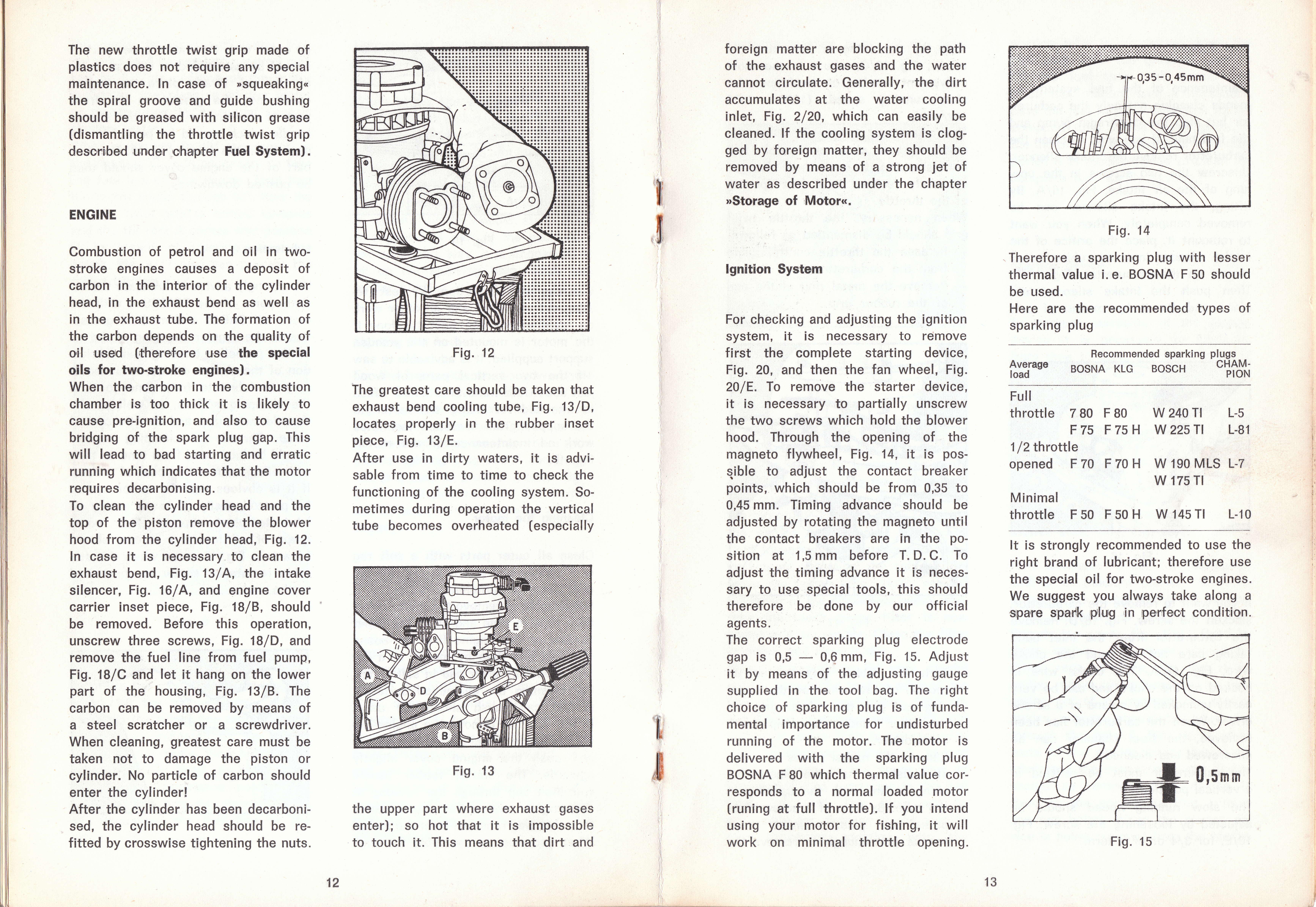
Combustion of petrol and oil in twostroke engines causes a deposit of carbon in the interior of the cylinder head, in the exhaust bend as well as in the exhaust tube. The formation of the carbon depends on the quality of Oil ,U,S€ld (,the,re,f,Ore ,U,S,e the SpeCial oils for two-stroke e,ngines), When the carbon in the combustion chamber is too thick it is likely to cause pre-ignition, and also to cause bridging of the spark plug gap. This will lead to bad starting and erratic running which indicates that the motor requires decarbonising. To clean the cylinder head and the top of the piston remove the blower hood from the cylinder head, Fig. 12. In case it is necessary to clean the exhaust bend, Fig. 13 / A, the intake silencer, Fig. 16/A, and engine cover carrier inset piece, Fig. 1S/8, should be removed. Before this operation, unscrew three screws, Fig. 18/D, and remove the fuel line from fuel pump, Fig. 18/C and let it hang on the lower part of the housing, Fig. 13/8. The earbon can be removed by means of a steel scratcher or a screwdriver. When cleaning, greatest care must be taken not to damage the piston or cylinder. No particle of carbon should enter the cylinder! After the cylinder has been decarbonised, the cylinder head should be refitted by crosswise tightening the nuts. Fig. 12
The greatest care should be taken that exhaust bend cooling tube, Fig . 13 /D, locates properly in the rubber inset piece, Fig, 13/E. After use in dirty waters, it is advisable from time to time to check the functioning of the cooling system. Sometimes during operation the vertical tube becomes overheated (especially
Fig. 13
the upper part where exhaust gases enter); so hot that it is impossible to touch it. This means that dirt and
'il ,il
foreign matter are blocking the path of the exhaust gases and the water cannot circulate. Generally,'the dirt accumulates at , the water cooling inlet, Fig. 2/20, which can easily be cleaned. lf the cooling system is clogged by foreign matter, they should be removed by means of a strong jet of water as described under the chapter >gf9y6'g,e of ,Motor<<r
lgn,ition System
For checking and adjusting the ignition system, it is necessary to remove first the complete starting device, Fig.20, and then the fan wheel, Fig. 201E. To remove the starter device, it is necessary to partially unscrew the two screws which hold the blower hood. Through the opening of the magneto f lywheel, Fig. 14, it is posqible to adjust the contact breaker points, which should be from 0,35 to 0,45 mm. Timing advance should be adjusted by rotating the magneto until the contact breakers are in the position at 1,5 mm before T. D. C. To adjust the timing advance it is necessary to use special tools, this should therefore be done by our off icial agents. The correct sparking plug electrode gap is 0,5 0,6 mm, Fig. 15. Adjust it by means of the adjusting gauge supplied in the tool bag. The right choice of sparking plug is of f undamental importance for undisturbed running of the motor. The motor is delivered with the sparking plug BOSNA F 80 which thermal value corresponds to a normal loaded motor (runing at full throttle). lf you intend using your motor for f ishing, it will work on minimal throttle opening. Fig. 14
Therefore a sparking plug with lesser thermal value i. e. BOSNA F 50 should be used. Here are the recommended types of sparking plug
Average load
Hecommended s,parking plugs BosNA KLG BoscH OHAMPION
Fu ll throttle 780 FB0 F75 F75H 1 l2 throttle opened F 70 F 70 H
Minimal throttle F 50 F 50 H
It is strongly recommended to use the right brand of lubricant; therefore use the special oil for two-stroke engines. We suggest you always take along a spare g:parik rptl'uig,in pe,r,'fe'c,t conditio'n.
w 240 Tl L-5 W 225 TI L.Bl
W 190 MLS L-7 w 175 Tl
w 145 Tl L-10
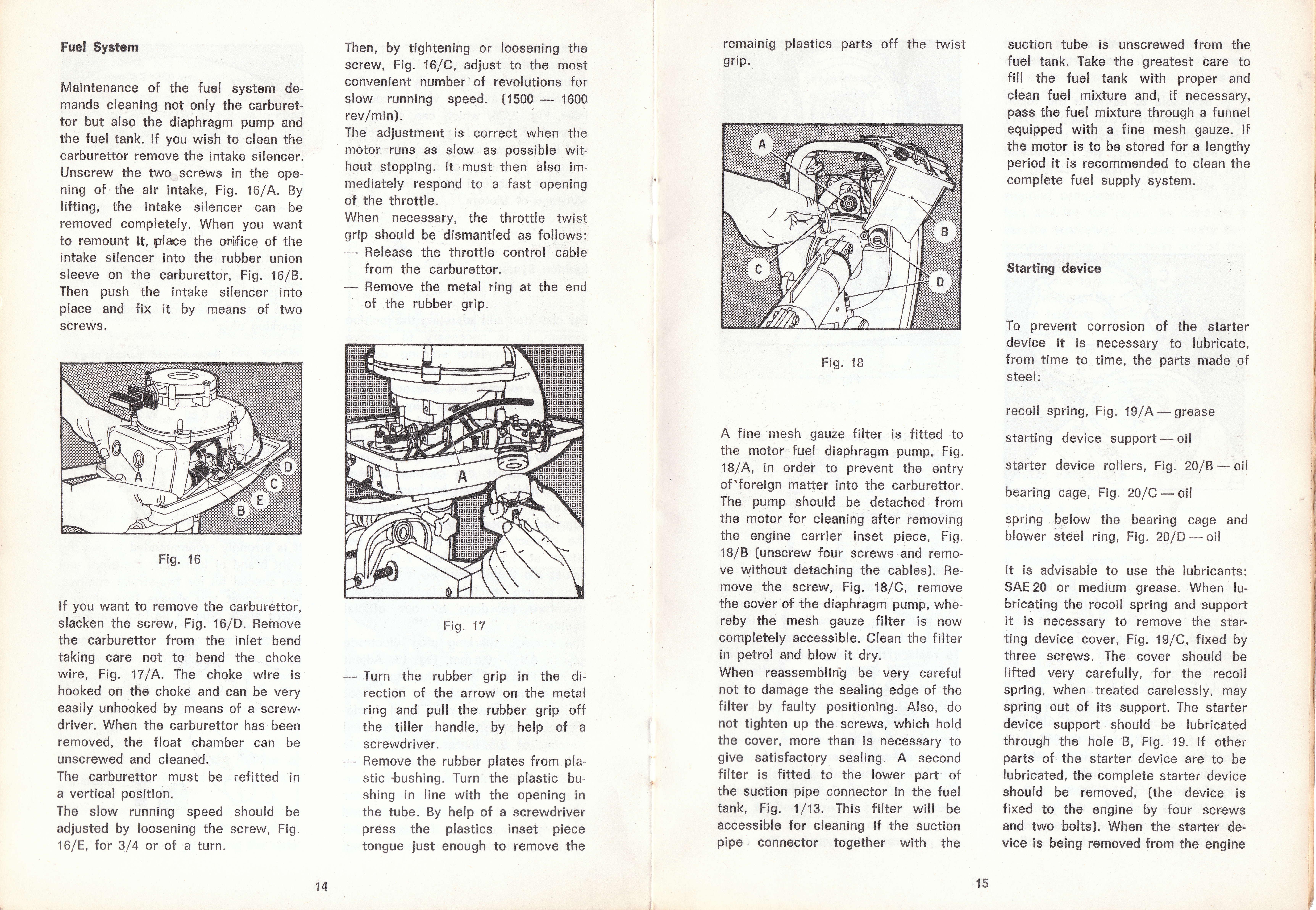
Maintenance of the fuet system demands cleaning not only the carburettor but also the diaphragm purnp and the fuel tank. lf you wish to clean the carburettor remove the intake silencer. Unscrew the two screws in the opening of the air intake, Fig, 16 / A. By lifting, the intake silencer can be removed completely. When you want to rermoun,t 'it, p,laice the ,o,ri'fii,ce of the intake silencer into the rubber union sleeve on the carburettor, Fig. 16/8. Then push the intake silencer into place and fix it by means of two screws, Then, by tightening or loosening the screw, Fig. 16'lC, adjust to the most convenient number' of revolutions for. sf ow running speed. ( 1 s00 1 G00 rev/min). The adjustment is correct when the motor 'runs as slow as possible without stopping. lt 'fflust then blso immediately respond to a fast opening of the throttle. When necessary, the throttle twist grip should be dismantled as follows:
Release the throttle control cable f rom the carburettor.
Hemove the metal ring at the end of the rubber grip.
Fig. 16
lf you want to remove the carburettor, slacken the screw, Fig. 16/D. Remove the carburettor from the inlet bend taking care not to bend the choke wire, Fig. 17 /A. The choke wire is hooked on the choke and can be very easily unhooked by means of a screwdriver. When the carburettor has been removed, the f loat chamber can be unscrewed and cleaned. The carburettor must be ref itted in a vertical position. The slow running speed should be adjusted by loosening the screw, Fig. 161E, for 3/4 or of a turn Fig. 17
Turn the rubber grip in the direction of the arrow on the metal ring and pull the rubber grip off the tiller handle, by help of a screwdriver.
stic Sushing. Turn the plastic bushing in line with the opening in the tube. By help of a screwdriver press the plastics inset piece tongue just enough to remove the suction tube is unscrewed f rom the f uel tank. Take the greatest care to fill the fuel tank with proper and clean fuel mixture and, if necess ary, pass the fuel mixture through a funnel equipped with a fine mesh gauze. lf the motor is to be stored for a lengthy period it is recommended to clean the complete fuel supply system.
Starting device
Fig. 1 I
A fine mesh gauze filter is fitted to the motor fuel diaphragm pump, Fig. 18/ A, in order to prevent the entry of'foreign matter into the carburettor. Ther pump should be detached f rom the motor for cleaning after removing the engine carrier inset piece, Fig. 18/B (unscrew four screws and remo. ve without detaching the cables). Remove the screw, Fig. 18/C, remove the cover of the diaphragm pump, whereby the mesh gauze filter is now completely accessible. Clean the filter in petrol and blow it dry. When reassembling be very careful not to damage the sealing edge of the filter by faulty positioning. Also, do not tighten up the screws, which hold the cover, more than is necessary to give satisfactory sealing.A second f ilter is f itted to the lower part of the suction pipe connector in the fuel tank, Fig. I /13. This filter will be accessible for cleaning if the suction pipe connector together with the To prevent corrosion of the starter device it is necessary to lubricate, from time to time, the parts made of steel:
recoil spring, Fig . 19/A- grease
starting device support - oil
starter device rollers, Fig. 2A/B - oil
bearing cage, Fig. 20/C- oit
spring below the bearing cage and blower steel ring, Fig . zA/D - oil
It is advisable to use the lubricants: SAE 20 or medium grease. When lubricating the recoil spring and support it is necessary to remove the starting device cover, Fig. 19 /C, f ixed by three screws. The cover should be lifted very carefully, for the recoil spring, when treated carelessly, may spring out of its support. The starter device support should be lubricated through the hole B, Fig. 19. lf other parts of the starter device are to be lubricated, the complete starter device should be removed, (the device is f ixed to the engine by four scr"ews and two bolts). When the starter device is being removed from the engine