13 minute read
2.6 Multi-Disk Brake with Brake/Spring Loaded Cylinder

Type : TC 25 Planetary-rigid axle in 6 Wheel Forwarder FW 1011 Drawing no.: SAP 7501.164 Valid as of Serial no. 01 Preparation of data : September, 30, 2005 Author: Rauh
• Note:
To work on the brake cylinder it is not required to remove the axle from the vehicle 2.6.1 Controlling Lift Opening of the Disks (Disks’ Wear)
(see Fig. 14) • Remove screw plug (No.157) and breather (No.57) (Fig. 1) • Release parking brake (release parking brake with pressure at spring loaded cylinder, connection (I))
Release pressure: min. 40 bar max. 80 bar • Measure and document distance„ X1 „ between both ball ramp disks with a feeler gauge • Parking brake in applied position (Spring loaded cylinder has no pressure) • Measure and document distance„ X2 „between both ball ramp disks with a feeler gauge • „ X1 „ - „ X2 „ = travel
Travel: min. 2.2 – 3.0 mm necessary
Adjusting and replacement: see section 2.6.2 and 2.6.4. 2.6.2 Controlling Cylinder Stroke and Adjustment
Controlling:
• Remove screw cap (No.154) with a wrench SW 24 and remove emergency bolt (No.155) • Parking brake in applied position (Spring loaded cylinder has no pressure).
Through the threaded hole of the piston (No.157), measure distance „ A1 „ and document (appropriate measuring instrument i.e. dial gauge or depth gauge), „ A1 „ = Distance from the adjusting allen bolt (No.158) to the end face of the housing (No.156). • Release parking brake. (release parking brake with pressure at spring loaded cylinder, connection (I))
Release pressure: min. 40 bar / max 80 bar
Through the threaded hole of the piston (No.157) measure distance „ A2 „ and document (appropriate measuring instrument i.e. dial gauge or depth gauge). „ A2 „ = Distance from the adjusting allen bolt (No.158) to the end face of the housing (No.156). • „ A1 „ - „ A2 „ = Cylinder stroke
Cylinder stroke: min: 5.0 - 6.0 mm necessary.
Type : TC 25 Planetary-rigid axle in 6 Wheel Forwarder FW 1011 Drawing no.: SAP 7501.164 Valid as of Serial no. 01 Preparation of data : September, 30, 2005 Author: Rauh
Adjustment:
Note: Adjust the cylinder stroke of the left and right brake separately. The adjusting bolt (No.158) is secured with Loctite 242 and fixed with a nut (No.159) and has a pitch of 1.5 mm. • Remove brake connection (I) at spring loaded cylinder (cyl. upper part / No.151) • Loosen 4 allen bolts (No.152) and remove spring loaded cylinder (cyl. upper part / No.151). Do not loosen both allen bolts (No.170). • Loosen locking nut (No.159), for this secure at pressure piston (No.164) at the wrench surfaces SW 16 from also turning • Remove adjusting allen bolt (No.158) complete. Clean thread of the adjusting allen bolt (No.158) and locking nut (No.159) of oil and adhesive residue • Screw on locking nut (No.159) again up to the head of the adjusting allen bolt (No.158) • Coat entire diameter and length of thread of adjusting allen bolt (No.158) with Loctite 242 • Screw in adjusting allen bolt (No.158) with allen wrench SW 8 into the pressure piston (No.164), until the screw in moment of approx. 8 - 15 Nm is clearly reached. The brake disks and the ball ramp activation mechanism are now next to one another without an movement gap. • Turn back the adjusting allen bolt (No.158) again about 3½ revolutions (corresponding to a travel of 5.25 mm) and lock in this position with the hex. nut (No.159). During this adjustment, secure the pressure piston (No.164) at the wrench surfaces SW 16 from also turning. With this adjustment is a disk opening movement of 2.4 mm achieved. • Tightening moment of the nut (No.159). • Should the cylinder-bottom part (No.162) or the pressure piston (No.164) be wetted with Loctiteresidue, the residue must be removed completely. • The opening movement is again controlled by measuring of the piston stroke after the adjustment. With an appropriate measuring instrument (i.e. dial gauge or depth gauge) measure the stroke movement of the pressure piston (No.164) with activation of the brake (connection II) and with release respectively. If the piston stroke execs a value of 5.25 the adjustment must be performed again. • Insert o-ring (No.176) into the groove of the cylinder bottom part (No.162) and install the spring loaded cylinder (No.151) onto the brake cylinder (No.150) and fasten with four allen bolts (No.152) „cross-wise“
Note: With these fastening bolts is simultaneously the disk spring packet (No.169) fasten. After fastening the spring loaded cylinder (No.151), the multi-disk brake is in applied position. • Insert hex. bolt (No.155) and o-ring (No.168) into the spring loaded cylinder (No.151) and tighten again screw plug (No.154)
Type : TC 25 Planetary-rigid axle in 6 Wheel Forwarder FW 1011 Drawing no.: SAP 7501.164 Valid as of Serial no. 01 Preparation of data : September, 30, 2005 Author: Rauh
Fig. 15 Fig. 16 2.6.3 Exchange of Spring Loaded Cylinder
• Secure vehicle with sufficient steps against rolling away • Ensure that both connections I and II have zero pressure • Remove screw plug (No.154) and take out hex. bolt (No.155) • Screw in emergency hex. bolt (No.155) clockwise until noticeably tight. Thereby the spring packet is completely under tension and the brake is released • Loosen 4 allen bolts (No.152) and remove simultaneously, to prevent a jamming of the cylinder housing • Remove screw plug (No.154) and take out hex. bolt (No.155) of the new spring loaded cylinder • Screw in emergency hex. bolt (No.155) of the new spring loaded cylinder clockwise until noticeably tight. Thereby the spring packet is under tension. • Insert o-ring (No.176) into the groove of the cylinder-bottom part (No.162) and install the spring loaded cylinder (No.151) onto the brake cylinder (No.150) and fasten with four allen bolts (No.152) „cross-wise“
Type : TC 25 Planetary-rigid axle in 6 Wheel Forwarder FW 1011 Drawing no.: SAP 7501.164 Valid as of Serial no. 01 Preparation of data : September, 30, 2005 Author: Rauh
• Screw open emergency hex. bolt (No.155).
After loosen the emergency hex. bolt (No.155), the multi-disk brake is in the brake position. • The travel must be checked by measuring the piston stroke after the assembly. With an appropriate measuring instrument (i.e. dial gauge or depth gauge) measure the stroke of the spring loaded cylinder (No.164) when activating the brake (connection II) and when releasing the brake. If the piston stroke exceeds a value of 5.25 the adjustment must be performed again. • Insert hex. bolt (No.155) and o-ring (No.168) into the spring loaded cylinder (No.151) and screw on plug (No.154) again and hand tighten. • At standstill both the operating- as well as the parking brake are to be activated alternatively, to ensure the orientation of individual parts. • Both pressure chambers of the cylinders are to be vented at the breather (III) after assembly to ensure, that there is no air in the lines.
Type : TC 25 Planetary-rigid axle in 6 Wheel Forwarder FW 1011 Drawing no.: SAP 7501.164 Valid as of Serial no. 01 Preparation of data : September, 30, 2005 Author: Rauh
2.6.4 Prime Adjustment of Cylinder Stroke
(see Fig. 15/16)
Note: The cylinder stroke of the left and right brake must be adjusted separately. The adjusting bolt (No.158) is secured with Loctite 242 and fixed with a nut (No.159) and has a pitch of 1.5 mm. • Remove brake connection (I) at spring loaded cylinder (cyl. upper part / No.151) • Loosen 4 allen bolts (No.152) and remove spring loaded cylinder (cyl. upper part / No.151). Do not loosen both allen bolts (No.170) • Loosen locking nut (No.159), for this secure pressure piston (No.164) at the wrench surfaces SW 16 from also turning. • Remove adjusting allen bolt (No.158) complete. Clean thread of the adjusting allen bolt (No.158) and locking nut (No.159) of oil and adhesive residue. • Screw on locking nut (No.159) again up to the head of the adjusting allen bolt (No.158) • Coat entire diameter and length of the thread of adjusting allen bolt (No.158) with Loctite 242 • Screw in adjusting allen bolt (No.158) with an allen wrench SW 8 into the pressure piston (No.164), until the screw-in moment of approx. 8 - 15 is clearly reached. The brake disks and the ball ramp activation mechanism are now next to one another without an movement. • Turn back the adjusting allen bolt (No.158) again by about 3½ revolutions (corresponding to a distance of 5.25 mm) and lock in this position with hex. nut (No.159). During this adjustment, secure the pressure piston (No.164) at the wrench surfaces SW 16 from also turning. With this adjustment is a disk opening travel of 2.4 mm achieved. • Tightening moment of nut (No.159). • Should the cylinder-bottom part (No.162) or the pressure piston (No.164) be wetted with Loctite residue, the residue must be removed completely. • The travel must be checked by measuring the piston stroke after assembly. With an appropriate measuring instrument (i.e. dial gauge or depth gauge) measure the stroke of the pressure piston (No.164) with activation of the brake (connection II) and with release respectively. If the piston stroke exceeds a value of 5.25 the adjustment must be performed again. • Insert o-ring (No.176) into the groove of the cylinder-bottom part (No.162) and install the spring loaded cylinder (No.151) onto brake cylinder (No.150) and fasten with four allen bolts (No.152) „cross-wise“.
Note: With these fastening bolts is simultaneously the disk spring packet (No.169) fasten. After fastening the spring loaded cylinder (No.151), the multi-disk brake is in brake position. • Insert hex. bolt (No.155) and o-ring (No.168) into the spring loaded cylinder (No.151) and again tighten screw plug (No.154) • At standstill both, the operating- as well as the parking brake are to be activated alternatively, to ensure the orientation of individual parts. • Both pressure chambers of the cylinders are to be vented at the breather (III) after assembly, to ensure, that there is no air in the lines.
Type : TC 25 Planetary-rigid axle in 6 Wheel Forwarder FW 1011 Drawing no.: SAP 7501.164 Valid as of Serial no. 01 Preparation of data : September, 30, 2005 Author: Rauh
2.6.5 Exchange of Brake Cylinder
• Secure vehicle with sufficient steps against rolling away • Ensure zero pressure at both connections I and II • Remove screw plug (No.154) and take out hex. bolt (No.155) • Screw in emergency hex. bolt (No.155) clockwise until noticeably tight. Thereby the spring packet is completely under tension and the brake is released • Loosen 4 allen bolts (No.152) and remove simultaneously, to prevent jamming of the cylinder housing, and remove the spring loaded cylinder (No.151) completely • Loosen three allen bolts (No.112) and if possible, remove evenly • Remove the complete assembled brake cylinder (No.150) from axle beam (No.65) • Insert new o-ring (No. 178) into the groove of the cylinder-bottom part (No.162) • Feed complete brake cylinder (No.150) into the bore of the axle beam (No.65) and during this, pay attention, that the sides of the compression wedge (No.181) are parallel to the pressure rollers (No.182). Tighten allen bolts (No.112) with 45 Nm. • Perform prime adjustment of the cylinder stroke as per section 2.6.4. • Insert o-ring (No.176) into the groove of the cylinder-bottom part (No.162) and install the spring loaded cylinder (No.151) onto the brake cylinder (No.150) and fasten the four allen bolts (No.152) with new spring washers (No.153) „cross-wise“. Tightening moment for allen bolts (No.152) is 45
Nm • Screw open emergency hex. bolt (No.155).
After loosening the emergency hex. bolt (No.155), the multi-disk brake is in the brake position • The movement gap must be checked by measuring the piston stroke after the assembly. With an appropriate measuring instrument (i.e. dial gauge or depth gauge) measure the stroke movement of the pressure piston (No.164) by activation of the brake (connection II) and by release respectively. If the piston stroke exceeds a value of 5.25 a new adjustment must be performed. • Insert hex. bolt (No.155) and o-ring (No.168) into the spring loaded cylinder (No.151) and screw on screw plug (No.154) again and hand tighten. • At standstill both, the operating- as well as the parking brake are to be activated alternatively, to ensure an orientation of individual parts. • Both pressure chambers of the cylinders are to be vented at the breather (III) after assembly, to ensure, that there is no air in the lines.
2.6.6 Exchange of Disks and Ball Ramp Activation Mechanism
Note:
For work on this part of the brake, the axle must be removed from the vehicle (see Fig. 5/15/17) • Disassemble side component as per section 2.1 • Disassemble brake cylinder as per section 2.6.5 • Pull off toothed rings (No.121) • Take out disk packet (No.119) / (No.120) complete with ball ramp activation mechanism (No.118) from the axle beam
Type : TC 25 Planetary-rigid axle in 6 Wheel Forwarder FW 1011 Drawing no.: SAP 7501.164 Valid as of Serial no. 01 Preparation of data : September, 30, 2005 Author: Rauh
Note for assembly: The principle components of the ball ramp activation mechanism (No.118) are only exchangeable as complete assembled units. The tension springs can be dismounted and exchanged. The layer arrangement of the multi-disk brake is put together as per the following: Three outer disks (No.119) and three inner disks (No.120) of the disk packet are assembled in the represented manner (Fig.17). First insert an outer disk (No.119), and then alternate between an inner disk (No.120) and an outer disk (No.119). At the ball ramp activation mechanism (No.118) would be an inner disk (No.120) on both sides.
Fig. 17 • Both outer disks (No.119) of each brake side are to be assembled onto the straight pins (No. 122) „cross-wise“. Each inner most outer disk of each side is not mounted to the straight pins (No.122) anymore, but into both coupler catches of the ball ramp activation mechanism (No.118). During assembly pay attention, that the four oil cooling openings of the inner disk line up. • Align hub profile of the 6 inner disk (No.120) with a profiled mandrel (i.e. sun gear shaft (No.140)) • After all six outer disks (No.119) and six inner disks (No.120) and the ball ramp activation mechanism (No.118) have been assembled, a toothed ring (No. 121) is slid onto all four straight pins (No.122) to assist assembly. • Replace o-rings (No.5) • Reinstall complete side component, for this mesh the external spline of the axle shaft into the compensating gears by light turning at the cardan flange • Then slide together axle beams until flange location, observing the straight pins • Insert hex. bolt (No.39 / Fig. 5). Tightening moment is 400 +10 Nm • Install axle into vehicle (connect brakes and cardan flange) • Fill oil into differential • Do not forget to vent the brake! • Test drive and retighten the axle mounting bolt
Type : TC 25 Planetary-rigid axle in 6 Wheel Forwarder FW 1011 Drawing no.: SAP 7501.164 Valid as of Serial no. 01 Preparation of data : September, 30, 2005 Author: Rauh
NAF Tool table for TC 25 axle
Description: WZ number:
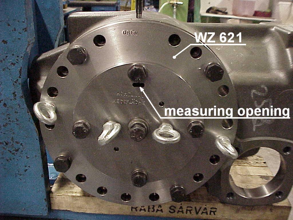
Insert punch to insert the seal rings 1160.208 on cardan flange (with WZ 282 for inner oil seal) (with WZ 213 for outer oil seal) Insert punch to insert the bearings 1110.030 and 111.073 in differential and pinion Orifice flange to adjust the bearing preload on diff. cage and the backlash on crown wheel / pinion in differential Groove socket wrench for groove nut 7329.073 in wheel hub Installer tool for slide ring 1180.325 in wheel hub Extractor plate to pull off the inner part from the planetary cage in planetary drive system WZ 282 WZ 213
WZ 075 WZ 283
WZ 621
WZ 081
WZ 234
WZ 190
Type : TC 25 Planetary-rigid axle in 6 Wheel Forwarder FW 1011 Drawing no.: SAP 7501.164 Valid as of Serial no. 01 Preparation of data : September, 30, 2005 Author: Rauh
Revisions reserved Neunkirchen on the September, 30, 2005