5 minute read
Update data


INTRODUCTION GENERAL WARNINGS REGARDING THE ELECTRICAL SYSTEM
Before overhauling, clean the assemblies and make sure they are intact and complete. Place in an orderly fashion and in appropriate containers the parts removed or disassembled with their respective fixing elements (screws, nuts, etc.). Check the integrity of the parts that prevent the loosening of screws: split washers, split pins, clips, etc. Self-locking nuts with nylon inserts must always be replaced. Avoid contact of rubber with diesel fuel, petrol or other incompatible substances. Before pressure washing mechanical parts, protect electrical connectors and any control units. The tightening of screws and nuts should always be carried out according to directions; FPT's sales and assistance network is available to provide any clarifications necessary to carry out any repair work not covered by this document. Before welding: ● Disconnect all electronic control units and unplug the power cable from the battery's positive terminal (connecting it to the chassis ground) and connectors. ● Remove paint by using proper solvents or paint removers and clean relevant surfaces with soap and water. ● Wait approximately 15 minutes before proceeding with welding. ● Use suitable fire-resistant protections to protect hoses or other components in which fluids or other flammable materials flow when welding. Should the vehicle be subjected to temperatures exceeding 80 °C (dryer ovens), remove the electronic control units.
The disposal of all liquids and fluids should be carried out in strict compliance with specific regulations in force.
GENERAL WARNINGS REGARDING THE ELECTRICAL SYSTEM
When having to operate on the electrical/electronic circuit, disconnect the batteries from the circuit, disconnecting the chassis ground cable first of all from the negative terminal of the battery. Before connecting the batteries to the system, make sure that the system is suitably insulated. Disconnect the external recharging apparatus from the public utility network before removing the apparatus pins from the battery terminals. Do not cause sparks to verify the presence of voltage in a circuit. Do not use a test lamp to verify circuit continuity, but proper control equipment only. Make sure that the wirings of electronic devices (length, type of cable, location, strapping, connection of screen braiding, grounding, etc.) conform with the FPT system and that they are carefully restored after repair or maintenance work. Measurements on ECUs, on plug-connectors as well as on electrical connections can be made only on suitable testing lines, by means of special plugs and plug-type bushes. Do not use in any case inappropriate means as metallic threads, screwdrivers, clips or similar. In addition to the risk of causing a short circuit, this might damage plug-type connections and this would then give rise to contact problems.
INTRODUCTION Grounding and screening
Do not use fast chargers to start up the engine. Start up must only be performed with either separate batteries or special truck. Incorrect polarisation of voltage supply to the electronic control units (for example, incorrect polarization of batteries) may lead to their destruction. Disconnect the batteries from the system before recharging them by means of an external unit. on connecting, only screw connector (temperature sensors, pressure sensors, etc.) nuts to the prescribed tightening torque. Isolate the circuit prior to disconnecting the junction connector from an electronic control unit. Do not directly supply current to components served by electronic control units with nominal vehicle voltage. The cables must be routed in such a way as to be parallel to the reference plane, as close as possible to the chassis/body. Upon completing work on the electrical circuit, restore the electrical connectors and wiring as originally provided. Key storage procedures are affected by electromagnetic disturbances such as cell phones and the like. Therefore, during key storage: 1. Make sure there are no sources of disturbance near the keys or in the cab. 2. Keys not inserted in the panel must be at least 1 metre away. Note The connectors are viewed from the cable side. Connector views contained in the manual are representative of cable side.
For fuse identification and rating, comply with the indications present in the vehicle, since their identification or rating may be subject to changes.
Grounding and screening
185272
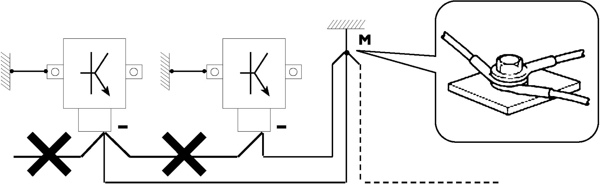
Figure 1 The negative conductors connected to a system ground point must be as short as possible and connected with each other in star shape, so trying that their tightening is organised and appropriate ref. (M).
INTRODUCTION Optional electrical and mechanical parts installations
C d C d
The following precautions must be observed regarding the electronic components: ● electronic control units must be connected to the system ground when equipped with metal housings. ● Electronic control unit negative cables must be connected to a system ground point, such as the dashboard compartment ground (avoiding "serial" or "chain" connections), as well as to the negative terminal of the battery/is. ● Even if not connected to the circuit ground/battery negative terminal, analogue ground (sensors) should have optimal insulation. Consequently, particular care should be given to terminal parasitic resistances: oxidation, clinching defects, etc. ● The metal braid of the shielded circuits must be in contact only at the control unit side to which the signal is to be sent. ● In the case of junction connectors the unshielded section (d), near to the latter, must be as short as possible. ● The cables must be routed in such a way as to be parallel to the reference plane, as close as possible to the chassis/body.
88039 Figure 2
Accessory installation, additions and changes on the vehicle must be carried out in compliance with the FPT assembly directives. it is reminded that, especially with regard to the electric system, several electric sockets are provided for as standard (or optional) sockets in order to simplify and normalise the electrical intervention by fitters. Any exception to the assembly directives must be authorized by FPT. lack of observance of above described prescriptions involves guarantee lapse. ▶ It is strictly forbidden to carry out any modifications or connections to the electric control unit wiring. In particular, the data line between the control units (CAN line) is to be considered untouchable.
