11 minute read
How to Read Performance Data Plate WARNING AND OPERATING INSTRUCTIONS

from Tadano Faun TR-500XL-3 Rough Terrain Crane Operation & Maintenance Manual SN 540239 - PDF DOWNLOAD

Notes For Lifting Capacities
General
1.Rated lifting capacities on the RATED LIFTING CAPACITY CHART apply only to the machine as originally manufactured and normally equipped by TADANO LTD. Modifications to the machine or use of optional equipment other than that specified can result in a reduction of capacity.
2.Construction equipment can be hazardous if improperly operated or maintained. Operation and maintenance of this machine must be in compliance with information in the operation, safety & maintenance manual supplied with machine. If these manuals are missing, order replacements through the distributor.
3.The operator and other personnel associated with this Machine shall fully acquaint themselves with the latest American National Standards Institute (ANSI) safety standards for cranes.
Set Up
1.Rated lifting capacities on the chart are the maximum allowable crane capacities and are based on the machine level on firm supporting surface under ideal job conditions. Depending on the nature of the supporting surface, it may be necessary to have structural supports under the outrigger floats or tires to spread the loads to a larger bearing surface.
2.For outrigger operation, outriggers shall be properly extended with tires free of supporting surface before operating crane.
Operation
1.Total rated loads have been tested to and meet minimum requirements of SAE J1063 - Cantilevered Boom Crane Structures - Method of Test.
2.Rated lifting capacities do not exceed 85 % of the tipping load on outriggers fully extended as determined by SAE J765 - Crane Stability Test Code. Rated lifting capacities for partially extended outriggers are determined from the formula. Rated Lifting Capacity = (Tipping Load - 0.1 x Tip Reaction) / 1.25.
3.Rated lifting capacities above blue lines in the chart are based on crane strength and those below, on its stability. They are based on actual load radius increased by boom deflection.
4.Rated lifting capacities include the weight of main hook block (1,100 lbs. for 50 ton capacity), optional secondary hook block (580 lbs. for 22 ton capacity), auxiliary hook block (330 lbs. for 6.2 ton capacity), sling and auxiliary lifting devices and their weights shall be subtracted from the listed capacities to obtain the net load to be lifted.
5.Rated lifting capacities are based on freely suspended loads and make no allowance for such factors as the effect of wind, sudden stopping of lads, supporting surface conditions, inflation of tires, operating speeds, side loads, etc. Side pull on boom or jib is extremely dangerous.
6.Rated lifting capacities do not account for wind on lifted load or boom. Rated lifting capacities and boom length shall be appropriately reduced, when wind velocity is above 20 mph (9 m/sec).
7.Rated lifting capacities at load radius shall not be exceeded. Do not tip the crane to determine allowable loads.
8.Do not operate at boom lengths, radii, or boom angle, where no capacities are shown. Crane may overturn without any load on the hook.
9.When boom length is between values listed, refer to the rated lifting capacities of the next longer and next shorter booms for the same radius. The lesser of the two rated lifting capacities shall be used.
10.When making lifts at a load radius not shown, use the next longer radius to determine allowable capacity.
11.Load per line should not exceed 11,400 lbs. (5,200 kg) for main winch and 12,300 lbs. (5,600 kg) for auxiliary winch.
12.The boom angle before loading should be greater to account for deflection.
13.The 34.8 (10.6 m) boom length capacities are based on boom fully retracted. If not fully retracted [less than 47´ (14.3 m) boom length], use the rated lifting capacities for the 47´ (14.3 m) boom length.
14.Extension or retraction of the boom with loads may be attempted within the limits of the RATED LIFTING CAPACITY CHART. The ability to telescope loads is limited by hydraulic pressure, boom angle, boom length, crane maintenance, etc.
15.For lifting capacity of single top, reduce the rated lifting capacities of relevant boom by 1,000 lbs. (450 kg). Capacities of the single top shall not exceed 12,300 lbs. (5,600 kg) including main hook.
16.When erecting and stowing jib, be sure to retain it by hand or by other means to prevent its free movement.
17.6,200 lbs. (2,800 kg) shall be subtracted from the rated lifting capacities of the main boom, when jib is attached to main boom head. Jib weight is 2,200 lbs. (1,000 kg).
18.Use “OVERWIND CUTOUT” disable switch when erecting and stowing jib and when stowing hook block. While the switch is pushed, the hoist does not stop, even when overwind condition occurs.
19.For boom length with 32.2 (9.8 m) jib, rated lifting capacities are determined by loaded boom angle only in the column headed “110.6´ (33.7 m) boom + 32.2´ (9.8 m) jib”. For boom lengths with 56.1´ (17.1 m) jib, total rated loads are determined by loaded boom angle only in the column headed “110.6´ (33.7 m) boom + 56.1 (17.1 m) jib”. For angles not shown, use the next lower loaded boom angle to determine allowable capacity.
20.When lifting a load by using jib (aux. winch) and boom (main winch) simultaneously, do the following:
• Enter the operation status as jib operation, not as boom operation.
• Before starting operation, make sure that weight of load is within rated lifting capacities for jib.
Definitions
1.Load Radius: Horizontal distance from a projection of the axis of rotation to supporting surface before loading to the center of the vertical hoist line or tackle with load applied.
2.Loaded Boom Angle: The angle between the boom base section and the horizontal, after lifting the rated lifting capacities at the load radius.
3.Working Area: Area measured in a circular arc about the centerline of rotation.
4.Freely Suspended Load: Load hanging free with no direct external force applied except by the hoist line.
5.Side Load: Horizontal side force applied to the lifted load either on the ground or in the air.
Notes For On Rubber Lifting Capacities
1.Rated lifting capacities on rubber are in pounds and do not exceed 75 % of tipping loads as determined by SAE J765 - Crane Stability Test Code.
2.Rated lifting capacities shown in the chart are based on condition that crane is set on firm level surfaces with axle oscillation lockout applied. Those above blue lines are based on tire capacity and those below, on crane stability. They are based on actual load radius increased by tire deformation and boom deflection.
3.If the axle oscillation lockout cylinders contain air, the axle will not be locked completely and rated lifting capacities may not be obtainable. Bleed the cylinders according to the operation, safety and maintenance manual.
4.Rated lifting capacities are based on proper tire inflation, capacity and condition. Damaged tires are hazardous to safe operation of crane.
5.Tire shall be inflated to correct air pressure.
6.Over front operation shall be performed within 2 degrees in front of chassis.
7.On rubber lifting with “jib” is not permitted. Maximum permissible boom length is 85´ (25.9 m).
8.When making lift on rubber, set parking brake.
9.For creep operation, boom must be centered over front of machine, swing lock engaged, and load restrained from swinging. Travel slowly and keep the lifted load as close to the ground as possible, and especially avoid any abrupt steering.
10.Do not operate the crane while carrying the load.
11.Creep is motion for crane not to travel more than 200 ft. (60 m) in any 30 minute period and to travel at the speed of less than 1 mph (1.6 km/h).
12.For creep operation, set Drive select switch to “4WHEEL(Lo)” and set gear shift lever to “1”.
NOTES FOR LOAD MOMENT INDICATOR (AML-L)
1.When operating crane on outriggers:
• Set P.T.O. switch to “ON”.
• Press the outrigger mode select key to register for the outrigger operation. The outrigger mode indicative symbol changes from flickering in lighting.
• Press the boom mode select key to register the boom mode. Each time the boom mode select key is pressed, the mode changes. Select the status that corresponds to the actual state of the boom.
• When erecting and stowing jib, select the status of jib set (Jib state indicative symbol flicker).
2.When operating crane on rubber:
• Set P.T.O. switch to “ON”
• Press the outrigger mode select key. The outrigger mode indicative symbol will disappear as the ontire indicative symbol comes on. Each time the on-tire mode select key is pressed, the mode changes. Select the creep operation, the on-tire mode indicative symbol flicker.
• Press the boom mode select key to register the boom mode. However, pay attention to the following.
(1)For stationary operation.
• The front capacities are attainable only when the over front position symbol comes on. When the boom is more than 2 degrees from centered over front of chassis, 360° capacities are in effect.
• When a load is lifted in the front position and then swung to the side area, make sure the value of the LOAD MOMENT INDICATOR (AML-L) is below the 360° lifting capacity.
(2)For creep operation.
• The creep capacities are attainable only when boom is in the straight forward position of chassis and the over front position symbol is on. If boom is not in the straight forward position of chassis, never lift load.
3.A swing does not automatically stop even if the crane becomes overloaded.
4.During crane operation, make sure that the displays on front panel are in accordance with actual operating conditions.
5.The displayed values of LOAD MOMENT INDICATOR (AML-L) are based on freely suspended loads and make no allowance for such factors as the effect of wind, sudden stopping of loads, supporting surface conditions, inflation of tire, operating speed, side loads, etc.
For safe operation, it is recommended when extending and lowering boom or swinging, lifting loads shall be appropriately reduced.
6.LOAD MOMENT INDICATOR (AML-L) is intended as an aid to the operator. Under no condition should it be relied upon to replace use of capacity charts and operating instruction. Sole reliance upon LOAD MOMENT INDICATOR (AML-L) aids in place of good operating practice can cause an accident. The operator must exercise caution to assure safety.
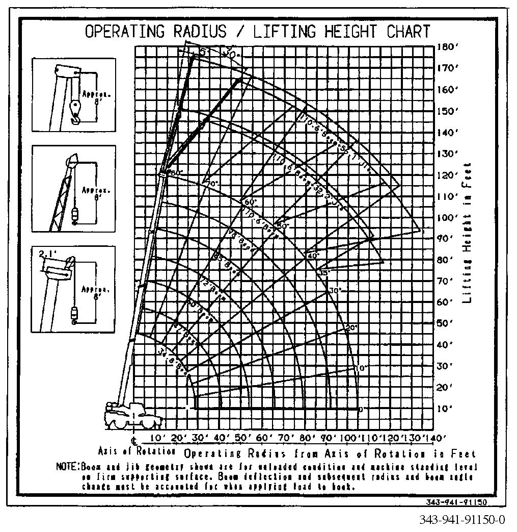
Load (Operating) Radius/Lifting Height Chart
◆ The following diagram is an example of the load (operating) radius/lifting height chart. The chart is located inside the cab.
◆ The load (operating) radius/lifting height chart does not include the effect of boom deflection. The greater the weight of the load is, the more the boom deflects, causing the load radius to increase somewhat. Take this effect into consideration when reading the load (operating) radius/lifting height chart.
The load (operating) radius/lifting height chart provides the load radii and lifting heights in relation to different boom lengths (jib lengths) and boom angles (jib offset angles). Use the chart in conjunction with the rated lifting capacity table when making an operation plan.
◆ While points A and B in the figure are at the same load radius, point A denotes the boom angle (or jib offset angle), and point B the lifting height.
Rated Lifting Capacity Table
Warning
The values shown in the rated lifting capacity table are based on ideal conditions where the crane is set level on a firm surface, there is no wind or side load, and the load is not swinging. When operating the crane under these conditions is not possible, reduce the load as necessary according to the actual operating conditions.
Rated lifting capacity tables are set up as shown below with the kind of job and the outrigger extension conditions. For actual values see the rated lifting capacity tables provided in the crane operator’s cab.
Kind of jobOutrigger extension
1. Outriggers extended Fully extended
2. Boom operation Extended to mid (21´ 11 3/4˝)
3. Single top operation
Jib operation
Outriggers not
4. extended (On-rubber)
Boom operation
Single top operation
Extended to mid (18´ 1/2˝)
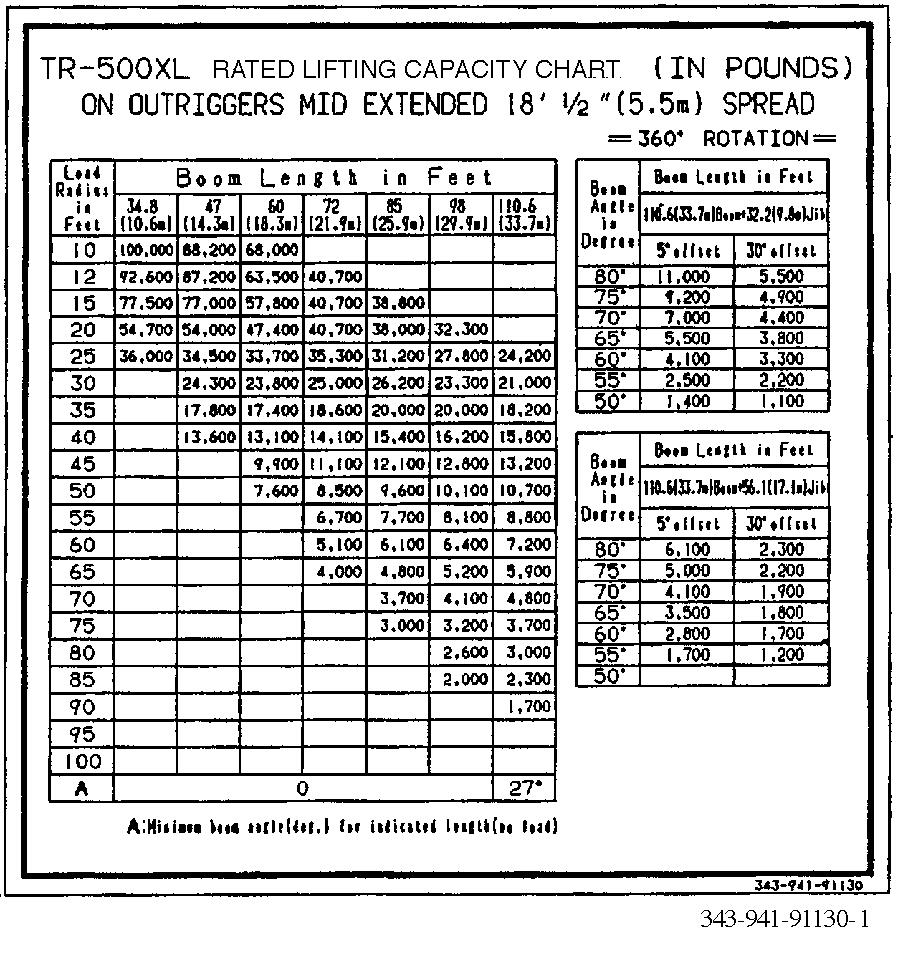
Below are some examples of rated lifting capacity charts.
[Example 1:Outriggers fully extended]

[Example 2:Outriggers extended to middle (21´ 11 3/4˝)]
[Example extended to middle (12´ 1/2˝)]


Boom Lift When Outriggers are Extended
See the applicable section of the rated lifting capacities table and find the rated lifting capacities value W (lbs.) that corresponds to the boom length L (ft) and load radius R (ft).
actual outrigger conditions. Read the correct rated lifting capacity for the jib length, jib offset angle, and boom angle.
◆ Rated lifting capacities are based on the condition that the crane is installed level on the firm level ground.
◆ Rated lifting capacities are based on the condition that the crane is installed level on the firm level ground. They include the weight of both the lifted load and slings.
◆ The values above the blue line are based on the crane strength and those below, on crane stability.
◆ Rated lifting capacities do not include the effect of wind on the load or the boom. If wind speed is beyond 20 mph (9 m/sec), decrease loading or shorten the boom.
◆ The rated lifting capacity values for boom lift assume a boom with jib and single top stowed.
◆ The rated lifting capacity values for boom lift are based on the load radius. The load radii shown in the rated lifting capacity table include the deflection of the boom under the weight of a load. When determining capacity from the table, therefore, find the rated lifting capacity value based on the actual measured load radius.
◆ When the actual boom length exceeds the length specified for a certain boom extension, compare the rated lifting capacity value for the specified length with that for one stage longer, and use the smaller of the two. (The value may be different from that indicated by the load moment indicator.)
Jib Lift when Outriggers are Extended
See the rated lifting capacity table which conforms to the
They include the weight of both the lifted load and slings.
◆ The values above the blue line are based on the crane strength and those below, on crane stability.
◆ For jib operation, rely only on the boom angle, regardless of boom length.
Single Top Lift when Outriggers are Extended
For operations with the single top, use the boom lift and on-outriggers section of the rated lifting capacity table to find the allowable load. Find the rated lifting capacity value based on boom length and load radius. From that value, subtract 1,000 lbs. (450 kg). The resultant value is the rated lifting capacity for a single top lift. However, remember that the maximum rated lifting capacity for a single top operation is 12,300 lbs. (5,600 kg). When the result of the above calculation (<table value> - 1,000 lbs [450 kg]) is over 12,300 lbs. (5,600 kg), always regard the rated lifting capacity as 12,300 lbs. (5,600 kg).
Boom Lift when Outriggers are not Extended (On-rubber)
Choose “Stationary” or “Creep”. Choose “Over Front” or “360° rotation”. Select the boom length. And then read out the rated lifting capacity W (lbs.) from the load radius L (ft).
◆ The “over-front area” in the table refers to an area indicated by the “over-front area” symbol in the load moment indicator display. This area lies in ±2° frontward of the carrier.
◆ The rated lifting capacities include the weight of the slings and the hook block.
◆ The values above the blue line are based on crane strength and those below, on crane stability.
◆ The load radii shown in the rated lifting capacities table include the deflection of the boom and the tires under the weight of a load. When determining capacity from the table, therefore, find the rated lifting capacities value based on the actual measured load radius.
◆ The rated lifting capacities values for on-rubber operation assume that the tires are at the specified air pressure and that the crane is set on firm and level ground with the suspensions locked.
◆ Do not perform jib lift. Do not perform boom lift with the boom length exceeding 85 ft (25.9 m).
◆“Creep” during on-rubber operation refers to traveling at a speed of 1 mph (1.6 km/h) or less and less than 200 feet (60 meters) in 30 minutes.
◆ Before traveling with load on hook, position the boom to the front and insert the swing lock pin.
◆ Do not operate the crane during traveling with a load on hook.
◆ For traveling with load on hook, shift the drive mode select switch to “4-WHEEL (Lo)”. Keep the gearshift lever to the first.
Single Top Lift When Outriggers are not Extended (On-rubber)
For operations with the single top mounted, use the boom lift and on-rubber section of the rated lifting capacity table to find the allowable load. Find the rated lifting capacity value based on boom length and load radius. From that value, subtract 1,000 lbs. (450 kg). The resultant value is the rated lifting capacity for a single top lift. However, remember that the maximum rated lifting capacity for a single top operation is 12,300 lbs. (5,600 kg). When the result of the above calculation (<table value> - 1,000lbs [450 kg]) is over 12,300 lbs. (5,600 kg), always regard the rated lifting capacity as 12,300 lbs. (5,600 kg).