2 minute read
INSTALLATION WITH THE PRE-RIGGED ITEMS FOR 2 CYCLE MODEL


couNTER ROTATTON MODEL OR DUAL ENG|NE,TTE-ROD KtT (OpilONAL - PARTS) TNSTALLATTON
TIE-ROD KIT (OPTIONAL PARTS) Contained parts
Item Part Name
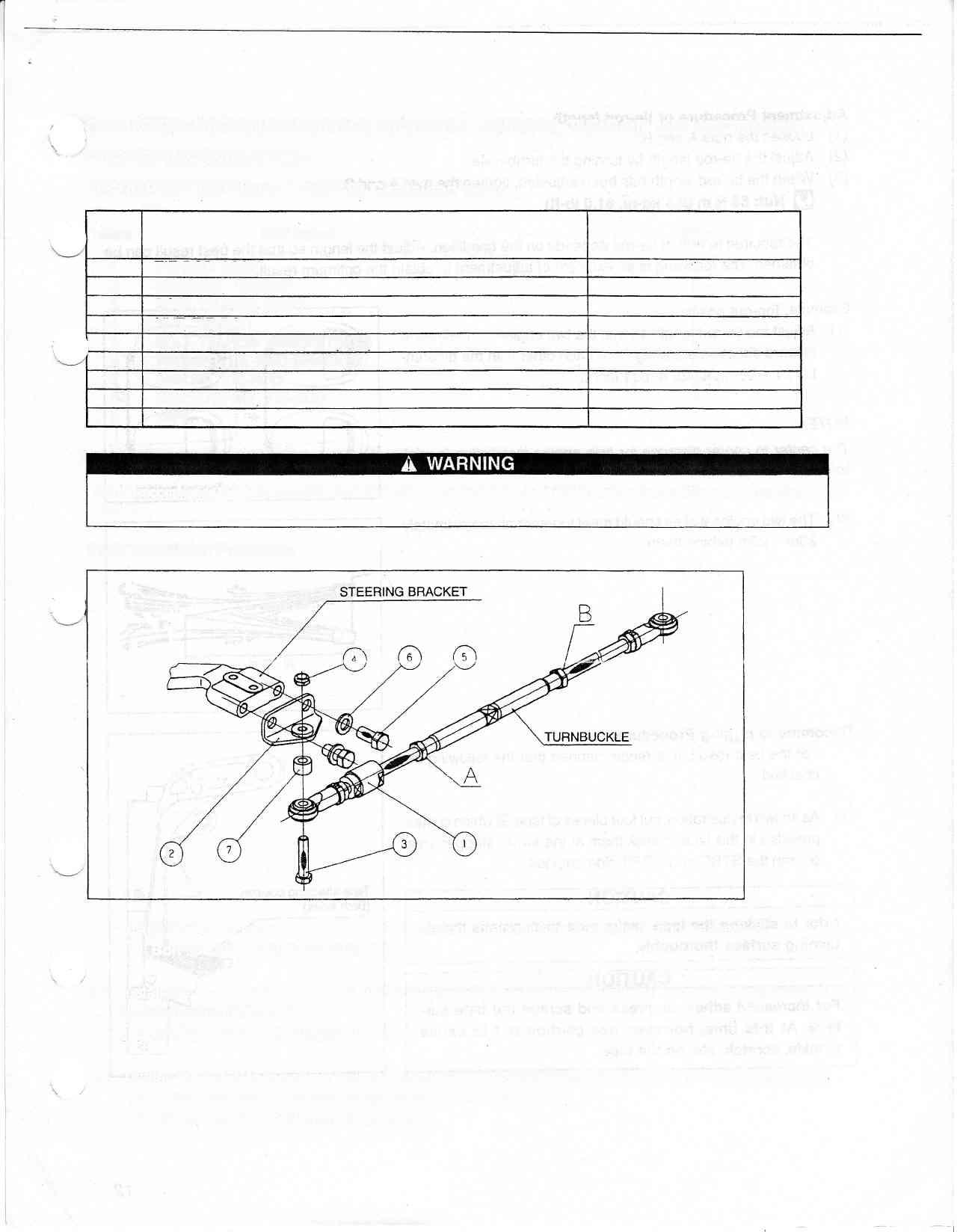
1 TIE.ROD ASSY 2 BRACKET, TIE-ROD 3 BOLT, TrE-ROD (UNF)
4 NUI TIE-ROD 5 BOLI TIE-ROD BRACKET(MI 2)
o WASHER. TIE-ROD BRACKET 7 SPACER. TIE.ROD 8 INSTRUCTION, TIE-ROD I TAPE Q'ty
1 2
z 2
4 4 2
4
1
Suzukirecommends that only authorized Suzuki outboard motor dealeror a qualified service mechanic pertorm installation of this kit.
Parts installation Procedure
(1) lnstalt the tie-rod bracket @ on the end of steering bracket using the bolts @ and washers @. [t eot @ : 85 N'm (8.5 kg-m, 61.0 lb-ft)
'- (2) Install the tie-rod assy e on the bottom side of tie-rod bracket @ with the spacer @ positioned in between using the bolt @. [! aon @ : 5o N.m (5.0 kg--, 36.0 lb-ft)
(3) Tighten the nut @ to tne end of bolt @ that has been installed in the step 2) above. (When tightening the \/. nut @, hold the bolt @ securely so as not to come loose.) S ttut @ : 30 N'm (3.0 kg-m,21.5 lb-ft)
Adjustment Procedure of tie-rod length (1) Loosen the nuts A and B. (2) Adjust the tie-rod tength by turning the turnbuckte. (3) lvhen the tie-rod length has been adjusted, tighten the nuts A and B.
Q Hur 85 N.m (8.5 kg-m,61.0 tb-ft)
The required lengih of tie-rod depends on the condition. Adjust the length so that the best result can be obtained. The following is an example of adjustment to obtain the optimum result.
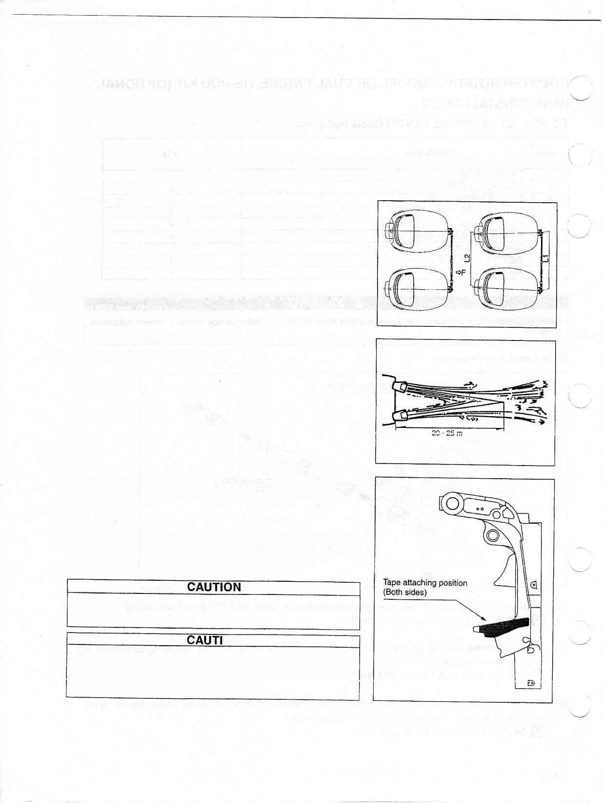
Example: Toe-out position (1) Adjust the tie-rod length so that the two engine centerlines in forward direction are away from each other with the differential L1 - L2 within 25 mm (1 inch).
NOTE: The center to center distance for twin engine instailation is minimum 635 mm (25 in.).
(2) The two engine wakes should meet together at approximately 20rn - 25m behind them.
Recommend rigging procedure
For the best result, it is recommended that the following be checked,
(1 ) As shown in illustration, cutfour pieces of tape @ which comes provided in this kit and stick them at the swivel stopper area of both the STBD and PORT side engines.
Prior to sticking the tape, make sure to degrease the attach ing surface thorou ghly.
O N For Increased adhesion, press and scrape the tape surface. At this time, however, use caution not to cause wrinkle, scratch, etc. on the tape.
Toe-out position