5 minute read
Remove the cylinder head bolts and


CYLINDER HEAD AND COMPONENTS
Four Cylinder, 267B, 301 B, 336BD and 336BDT Engines (Refer to Figure 5) Removal
Remove the muffler and hood from vehicle. Disconnect the exhaust system and air cleaner from the manifolds. Steam clean the entire area where service work is to be performed.
1. Drain the cooling system. CAUTION If the engine is hot, do not remove the radiator cap until the coolant has had sufficient time to cool. Loosen the cap to the first stop carefully to relieve any excess pressure before removing it completely. Remove the upper radiator and water pump hoses. 7. Remove the exhaust manifold (12) and discard the gaskets (13).
8. Remove the water manifold (14) and discard the gaskets (15). NOTE If the thermostat is to be serviced, remove the thermostat housing (28) and refer to
Section 25 of the Service Manual.
2. Disconnect the high pressure fuel lines from the injectors and the leak-off tubes between the cylinder heads. Cap them to prevent any foreign particles from entering. Remove the injectors as described in
Section 33 of the Service Manual.
3. Remove the breather tube (1) and discard the gaskets (2). Remove the manifold brace (5) and spacer (6), if equipped.
4. Remove the intake elbow (3) and gasket (4), if equipped and discarding the gasket.
5. Remove the intake manifold (7) and discard the gaskets (8).
6. Remove the exhaust stack (9) or cover plate (10) if equipped. Remove the exhaust elbow (11) if equipped. 9. Remove the valve cover nuts (14), bevel washers (15), gaskets (16), valve cover (17) and cover gasket (18). Discard gaskets (16 and 18).
10. Remove the studs (19), washers (20) and rocker arm assemblies (21). NOTE Tag the rocker arm assemblies for proper assembly. See Page 22-16 for serviCing.
Remove the push rods (22) and tag them for proper assembly.
11. Remove the cylinder head bolts and washers (23). Remove the cylinder head assembly (24), fire rings (25) and head gaskets (26) . Discard the fire rings and head gaskets. See Page 22-18 for servicing of the cylinder head.
rI I ...... ...... ...... ! I I I I ® e--®
I I
Figure 5

CYLINDER HEAD AND COMPONENTS Six Cylinder 401 B Engines (Refer to Figure 6) Removal
Remove the muffler and hood from vehicle. Disconnect the exhaust system and air cleaner from the manifolds. Steam clean the entire area where service work is to be performed.
1. Drain the cooling system. CAUTION If the engine is hot, do not remove the radiator cap until the coolant has had sufficient time to cool. Loosen the cap to the first stop carefully to relieve any excess pressure before removing it completely.
Remove the upper radiator and water pump hoses.
2. Disconnect the high pressure fuel lines from the injectors and the leak-off lines between the cylinder heads. Cap them to prevent any foreign particles from entering. Remove the injectors as described in
Section 33 of the Service Manual.
3. Remove the breather tube (1) and discard the gaskets (2).
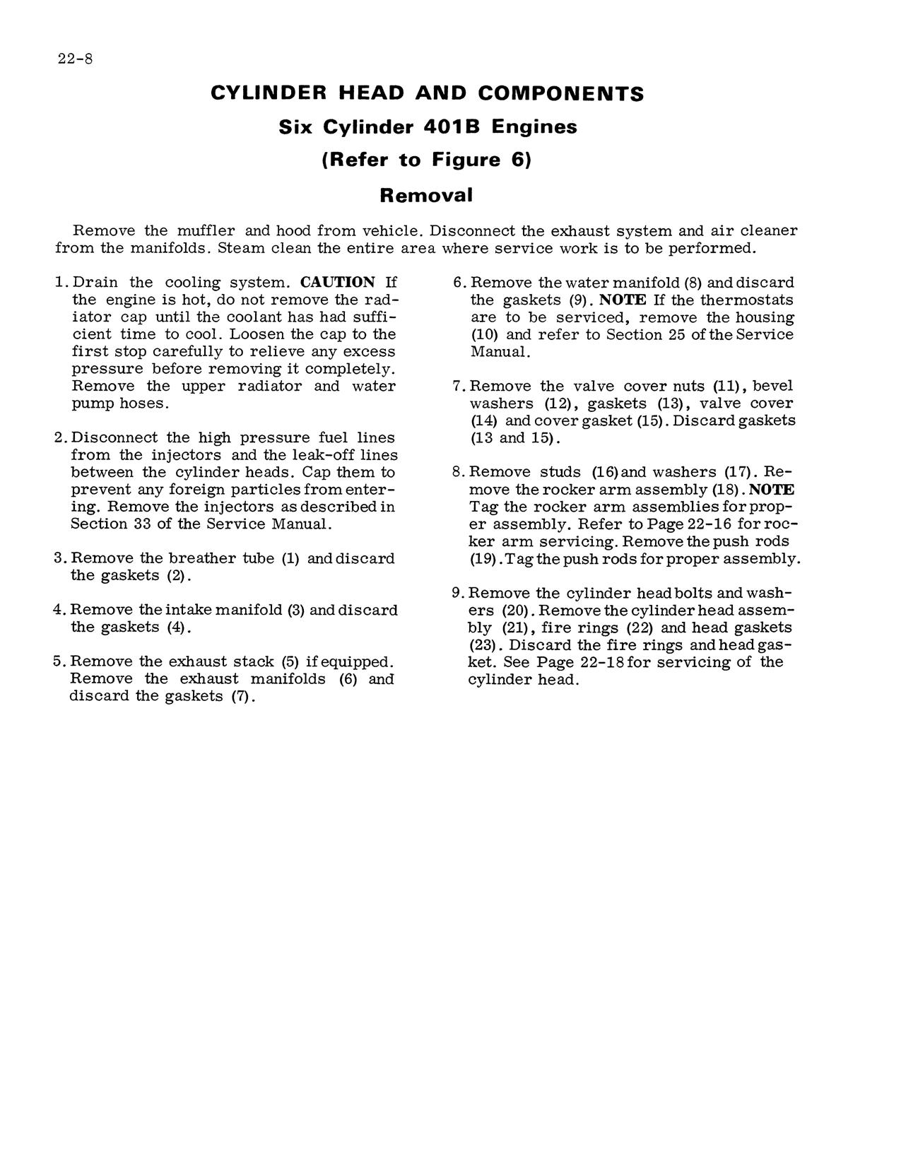
4. Remove the intake manifold (3) and discard the gaskets (4).
5. Remove the exhaust stack (5) if equipped.
Remove the exhaust manifolds (6) and discard the gaskets (7). 6. Remove the water manifold (8) and discard the gaskets (9) . NOTE If the thermostats are to be serviced, remove the housing (10) and refer to Section 25 of the Service
Manual.
7. Remove the valve cover nuts (11), bevel washers (12), gaskets (13), valve cover (14) and cover gasket (15). Discard gaskets (13 and 15).
8. Remove studs (16) and washers (17). Remove the rocker arm assembly (18) . NOTE
Tag the rocker arm assemblies for proper assembly. Refer to Page 22-16 for rocker arm servicing. Remove the push rods (19) . Tag the push rods for proper assembly.
9. Remove the cylinder head bolts and washers (20). Remove the cylinder head assembly (21), fire rings (22) and head gaskets (23). Discard the fire rings and head gasket. See Page 22-18 for servicing of the cylinder head.
Figure 6

Replace all gaskets, seals and worn or defective parts.
1. Clean the top surface of the block and sleeve flange carefully. All traces of carbon and other deposits must be removed. During cleaning, the use of a rag dampened in solvent is recommended.
2. Using extreme care not to scratch surfaces. Remove any small burrs in the areas to be measured so accurate readings can be obtai.ned.
3. Sleeve protrusion must be checked to determine which fire ring to install, Figure 7. Make sure the correct fire ring is used. Only the standard size fire ring is included in the valve grind gasket kit. However, a thicker fire ring is available if the protrusion chart indicates a need for it. The thicker fire ring can be identified by a blue marking stripe. Either a magnetic base dial indicator or a depth micrometer can be used to determine the cylinder sleeve protrusion as indicated in Figure 8. Measure cylinder sleeve protrusion at points A,B, C and D. Using plate, ball and clamping bar, clamp the cylinder sleeve in place, Figure 9. Torque the hold down caps crews 50 footpounds. NOTE Refer to Figure 9, Inset A for clamping bar dimensions. These tools are available through local Owatonna Tool dealers or the Owatonna Tool Co. Owatonna, Minnesota.

4. Clean and inspect the cylinder heads thoroughly. If evidence of fretting or erosion exists in the area of fire-ring contact or if head is warped more tban .005", the head must be resurfaced or replaced.
5. Inspect push rods for straightness, cracked or worn ends. Replace if necessary.
6. Clean all bolt and stud threads.
7. Clean the rocker arm covers and discard the old gasket.
8. Replace all hoses if cracks and deterioration is found. Replace hose clamps to assure a tight connection.
CYLINDER SLEEVE PROTRUSION USE STANDARD FIRE RING
BOTH SLEEVES UNDER ONE HEAD FLUSH TO .002"
BOTH SLEEVES UNDER ONE HEAD .002" OR OVER BUT LESS THAN .0025" BETWEEN SLEEVES
x
BOTH SLEEVES UNDER ONE HEAD OVER .0025" DIFFERENCE
BETWEEN SLEEVES ON THE
HIGH SLEEVE
Figure 7
USE OVERSIZE (THICKNESS) FIRE RING
x
ON THE
LOW SLEEVE