7 minute read
MerCruiser Thunderbolt IV and Thunderbolt V Systems


7-13 on page 113 show my favorite spark tester in use, but more on that later.
Engine misfires. Check the spark plugs and leads, rotor and distributor cap, and ignition coil for loose connections at the coil and ignition switch.
Also check the engine firing order, plug wire routing, and the engine timing.
Engine fires when cranked but stops when key
is released. Check the ignition switch and related wiring.
Engine cranks but doesn’t start. Check for spark
at the plugs; check the coil and bypass circuit to the coil positive terminal; and check the wiring. Also check the engine timing and plug wire routing, and the tachometer and related wiring.
Some of the items mentioned here, such as engine timing and tachometer wiring, have not yet been discussed, but I will cover them in the following sections. This list is a guide for inboard and inboard/ outboard (IO) engines only. Use it for sorting out your thoughts as you approach a problem. You must work with the specific information for your ignition system if you expect to be successful as an ignitionsystem diagnostician.
I will discuss two of the most common inboard engine electronic ignition systems, the MerCruiser Thunderbolt IV and Thunderbolt V. Other widely used systems with similar design and features are made by Prestolite and Delco. Use this chapter as a primer on electronic systems in general, and refer to the workshop manuals for the specific information you need to troubleshoot these other systems.
With about 75 to 80 percent of the market at this writing, MerCruiser is the largest producer of gasolinefueled inboard engines in the world. The Thunderbolt series of ignition systems has been quite popular over the years, and for the last 15 years the Series IV and Series V systems have been the mainstay of the MerCruiser line. The Thunderbolt IV system comes in two variations, one with a remotely mounted ignition module (located on the port side exhaust elbow) and the other with the ignition module mounted on the side of the distributor body.
Repair procedures for both variations are the same. Ignition-module replacement will be slightly different.
Service procedures for this system are not too difficult. Besides the generic procedures already mentioned for ignition systems, some specific system information follows.
Distributor-Cap Service
The distributor cap needs to be kept clean and dry. MerCruiser recommends periodically removing the cap (annually will be fine) and giving it a thorough inspection. Be sure to mark the high-tension wires with tape and a marker before removing them from the cap so you can be certain they go back in the same order.
Loosen the four screws that hold the cap in place and carefully lift the cap off its seat on the distributor. There should be a gasket between the cap and the edge of the distributor housing; be careful not to damage it. If it’s damaged in any way, it will have to be replaced. This gasket is an integral part of the ignition protection for the distributor. Look closely and observe the alignment tab molded into the cap and the corresponding indent on the body of the distributor housing. Upon reassembly, make sure this tab and groove are aligned; otherwise, damage to the distributor cap and rotor can occur the first time the engine turns over, regardless of whether it starts or not. Figure 7-5on page 108 shows the cap orientation with the position of the tab indicated.
Once you have the cap off, clean it thoroughly with warm soap and water and dry it (use compressed air if you have a supply). Next, carefully inspect the cap looking for excessive burning or corrosion. Check the center contact for deterioration. Minor corrosion, which is not unusual, can be removed with the tip of a straight-bladed screwdriver. Look for any signs of carbon tracking on both the inside and outside of the distributor cap. Carbon tracks will show up as random, fine lines etched into
Fig. 7-5. Distributor cap showing positioning tab. Make sure this tab is lined up with its corresponding groove in the distributor housing when reinstalling the cap. Fig. 7-6. Carbon tracking inside a distributor cap. These tracks provide a highly conductive path for your ignition voltage to short-circuit between cylinders.
the surface of the plastic. These tracks, often mistaken for cracks, are actually secondary voltage leaks short-circuiting the intended path. The spark actually etches a carbon groove into the surface of the cap. Carbon tracks are most often caused by dirt and oil accumulation on the cap. If there are any signs of carbon tracking, the cap will have to be replaced. Figure 7-6shows a carbon track on the inside of a four-cylinder distributor cap.
Next inspect the rotor-sensor wheel, located under the distributor cap. Again, you’ll be looking for corrosion and any signs of carbon tracking.
One problem with the Thunderbolt system is that this rotor is attached to the distributor’s center shaft with a product known as Loctite. As the name implies, Loctite is a kind of glue that secures the rotor to the shaft. Unlike most rotors that simply lift off the shaft against the pressure of a small spring clip, these rotors are on tight. Don’t expect to simply lift it off for inspection.
To remove the rotor, place two flat-bladed screwdrivers under the rotor at its base and push them snugly up against the distributor shaft. The screwdrivers should be at 180 degrees from one another. Push both screwdrivers down against the distributor housing, and hope the rotor pops off. If this doesn’t work, use an electric hair dryer on high heat and fan the rotor and sensor wheel until they begin to feel warm to the touch. Try prying again, but don’t bend the sensor wheel blades. The slightest distortion of the wheel will render it useless, so alignment of the blades with the sensor inside the distributor is critical. With diligence, the rotor will eventually lift off.
Once the rotor is removed, carefully inspect it for carbon tracks and any damage to the key inside the center section. Replace the rotor if there is any damage here. If all looks well, ensure that the tang that’s attached to the rotor and follows the center contact inside the distributor cap is bent to allow for 1⁄4 inch (6 mm) clearance, as shown in figure 7-7.

Ignition Sensor
Next, take a close look at the ignition sensor. It’s best to use a magnifying glass for this, because you’ll be
1⁄4
Fig. 7-7. Rotor contact bent to allow 1⁄4 inch clearance.
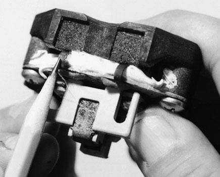
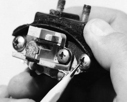
Fig. 7-8. MerCruiser ignition sensor, pointing out metal jumpers. These jumpers are famous for corroding through, effectively shutting down your ignition system. Fig. 7-9. Retaining screws holding an ignition sensor in place.
looking for hairline cracks, called jumpers, in the metal connecting links on the sensor. If you find any cracks, replace the sensor. Figure 7-8shows the sensor and points out the jumpers in question.
If the sensor does require replacement, it’s easily removed at this point by backing out the two retaining screws indicated in figure 7-9.
When you reassemble the distributor, you’ll need some Loctite (#271), which is available at any good auto-parts store. Apply several drops to the inside of the rotor at the positioning key and put several drops in the keyway on the distributor shaft where the key fits into the rotor. Immediately reinstall the rotor. Do not, under any circumstances, use a silicone-based sealer on the inside of the distributor (to repair the cap gasket, for example). As they cure, most silicone sealers give off acidic vapor that can cause corrosion on the ignition contact points and conductors inside the distributor.
MerCruiser Thunderbolt V System
The Thunderbolt V system offers some significant technological advantages over the Thunderbolt IV system, the most significant of which is known as the knock-retard spark control. This feature is a giant step forward in avoiding internal engine damage due to pinging. Engine cylinders are designed so that the compressed gas-air mixture burns very rapidly but progressively. When the mixture explodes instead of burns, a loud rapping or “pinging” noise is heard. Thus, pinging is sometimes called detonation.
Whatever it’s called, pinging is bad for your engine. Incorrect timing, low-quality fuel, or excessive carbon buildup inside the combustion chamber are the primary causes. If it’s allowed to continue, pinging will eventually cause valves and piston tops to literally melt away.
By adding two electronic devices to the ignition system, engineers have devised a way to minimize