7 minute read
Specific gravity of battery electrolyte U

NOTES: I The romots control lever should be shifted quickly. a When checking remote control lever operation, decrease engine speed to idling as soon as thrust force is transmitted to the boat. I lf thrust force is transmitted to the boat before engine speed is increased or if no thrust force is transmitted when engine speed is increased, contact the nearest dealer for inspection and servicing. @ Check safety switch for operation. (EP) After completing the above-mentixed inspection, remove lock plate from safety switch to see whether the engine stops. NOTE: lf the engine is stopped by means of the safety switch, be sure to turn the main switch key to the "STOP" position.
@ Spare parts and accessories Check spare parts, service tools and safety parts for damage. Ensure that none are missing.
@ Fuel level in fuel tank. Ensure fuel tank contains enough fuel for your boating schedule.
1 . M O U N T I N G O U T B O A R D , MOTOR {1) Transom
Nissan Marine outboard motors are availa' ble in two sizes to fit different transom heights. Generally, long shaft types which permit the freeboard to be maintained at a higher level are popular for safety reasons. The transom heieht is listed below.
Height of transom on boat Height of outboard motor transom
L 530 mm (20.86 in) XL 657 mm (25.87 in)
Height of transom on boal Center of boat width
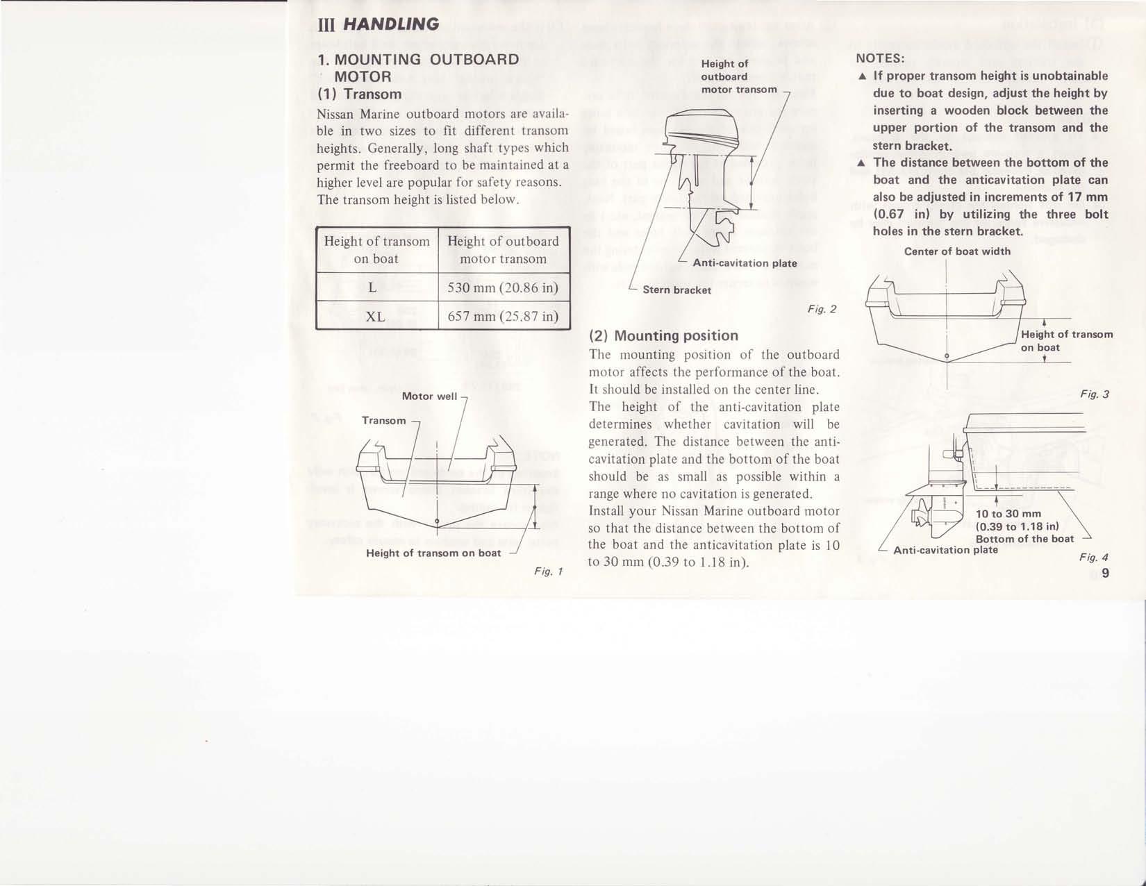
Fig. 2
(2) Mounting posation
The mounting position of the outboard motor affects the performance of the boat. It should be installed on the center line. The height of the anti-cavitation plate determines whether cavitation will be generated. The distance between the anticavitation plate and the bottom ofthe boat should be as small as possible within a range where no cavitation is generated. Install your Nissan Marine outboard motor so that the distance between the bottom of the boat and the anticavitation plate is 10 to 30 mm (0.39 to I .18 in). NOTES: r lf proper transom height is unobtainable due to boat design, adjust the height by inserting a wooden block between the upper portion of the transom and the stern bracket. .r The distance between the bottom of the boat and the anticavitation plate can also be adjusted in increments of 17 mm (0.67 in) by utilizing the three bolt holes in the stern bracket.
---r---
10 to 30 mm (0.39 to 1.18 in)
Bottom of the boat Anti-cavitation plato Fig. 4 9
@ Install the outboard motor correctly to the transom and securely tighten the stern bracket clamp screws with a wrench. NOTES: r To prevent dama,ge to the transom, insert a transom pad or other similar material between the stern bracket and the transom. a Do not tighten the clamp screws with excessive force, or the transom may be damaged. @ after tightening the stern bracket clamp screws, tighten the accessory bolts, nuts and washers to prevent the outboard motor from falling off.
First, tilt the outboard motor up to prepare for installation, drill two bolt holes on each side of the transom board by aligning with one of three mounting holes provided at the upper part of the stern bracket and with one of the long holes provided on the lower part. Next, apply sealant (silicone sealant, etc.) to the transom board bolt holes and the bolts to prevent water from entering the mounting holes. Then, tighten nuts with washers to secure the stern bracket. @ tt ttre outboard motor is equipped with a power trim mechanism, drill bolt holes in the transom board according to the "Stern bracket bolt hole dimensions" diagram before mounting the outboard motor. Insert bolts in advance in the left stern bracket. and install the outboard motor to the transom board according to the method explained above.
o Dimensions of stsrn bracket mounting holes
u) o
o l
Stern brackot (R.H.l
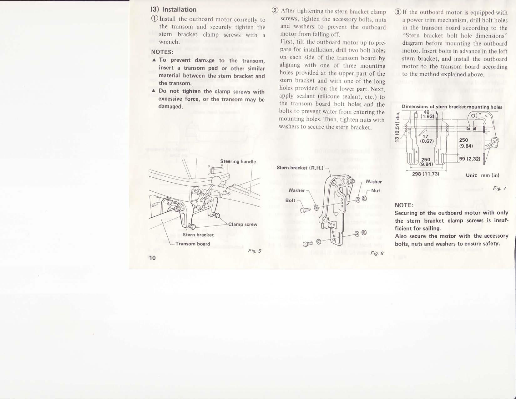
NOTE: Securing of the outboard motor with only the stern bracket clamp screws is insufficient for sailing. Also secure the motor with the accessory bolts, nuts and washers to ensure safety.
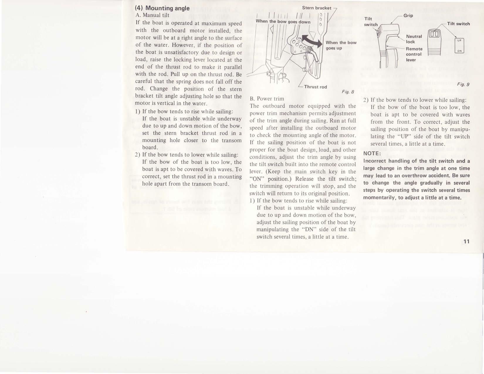
A. Manual tilt If the boat is operated at maximum speed with the outboard motor installed, the motor will be at a_right angle to the surface of the water. However, if the position of the boat is unsatisfactory due to design or load, raise the locking lever located at the end of the thrust rod to make it parallel with the rod. Pull up on the thrust rod. Be careful that the spring does not fall off the rod. Change the position of the stern bracket tilt angle adjusting hole so that the motor is vertical in the water. l) If the bow tends to rise while sailing:
If the boat is unstable while underway due to up and down motion of the bow, set the stern bracket thrust rod in a mounting hole closer to the transom board, 2) If the bow tends to lower while sailing:
If the bow of the boat is too low, the boat is apt to be covered with waves. To correct, set the thrust rod in a mounting hole apart from the transom board.
Noutral lock Remote control lever
,n-Tilt switch ---l- \ /@\ \ l l l " l t t l l
Thrust rod
Fic. I
B. Power trim The outboard motor equipped with the power trim mechanism permits adjustment of the trim angle during sailing. Run at full speed after installing the outboard motor to check the mounting angle of the motor. If the sailing position of the boat is not proper for the boat design, load, and other conditions, adjust the trim angle by using the tilt switch built into the remote control lever. (Keep the main switch key in the "ON" position.) Release the tilt switch; the trimming operation will stop, and the switch will return to its original position. 1) If the bow tends to rise while sailing:
If the boat is unstable while underway due to up and down motion of the bow, adjust the sailing position of the boat by manipulating the "DN" side of the tilt switch several times, a little at a time. 2) If the bow tends to lower while sailing:
If the bow of the boat is too low, the boat is apt to be covered with waves from the front. To correct, adjust the sailing position of the boat by manipulating the "UP" side of the tilt switch several times, a little at a time. NOTE: Incorrect handling of the tilt switch and a large change in the trim angle at one time may lead to an overthrow accident. Be sure to change the angle gradually in several steps by operating the switch several times momentarily, to adiust a little at a time.
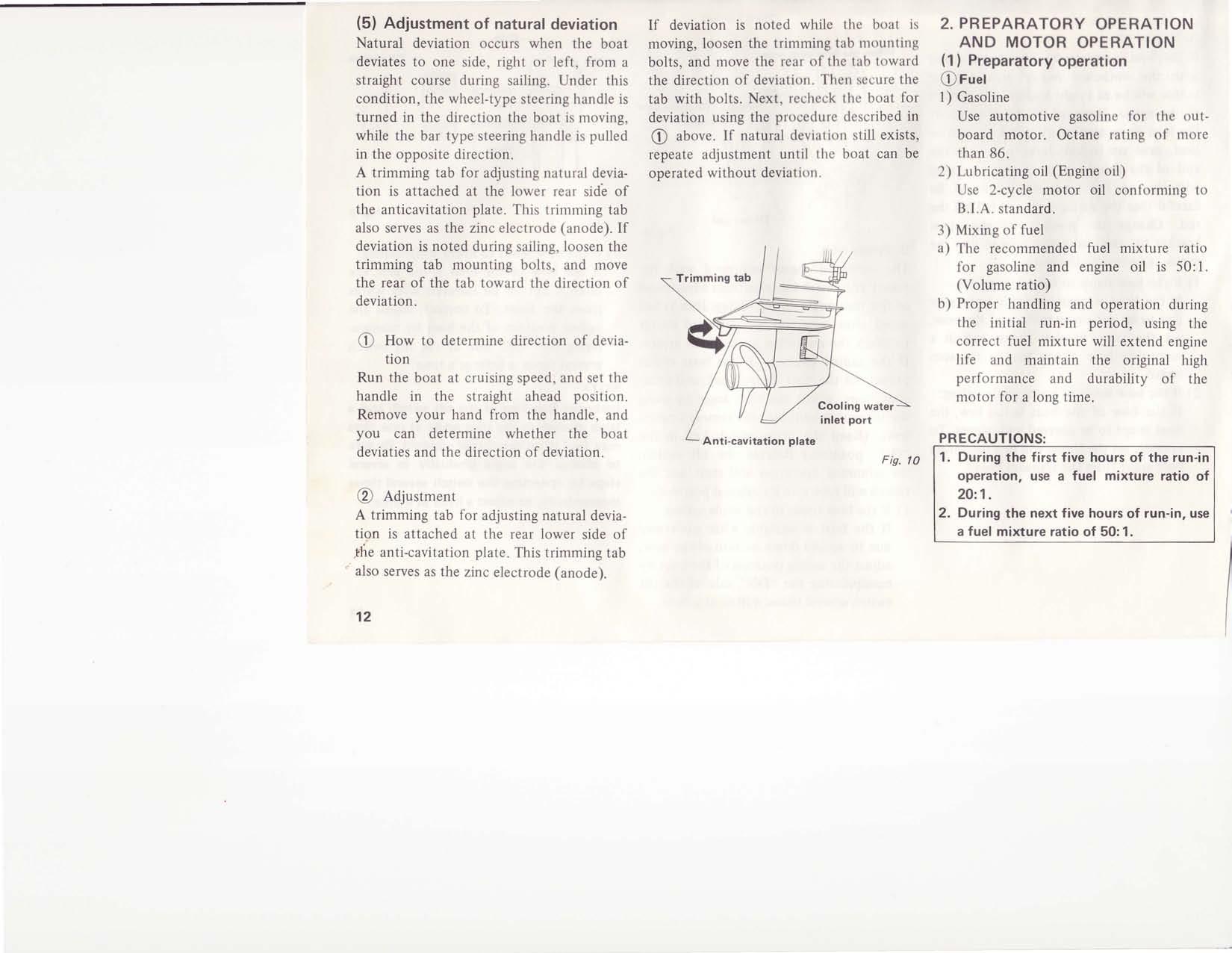
(5) Adjustment of natural deviation Natural deviation occurs when the boat deviates to one side, right or left, from a straight course during sailing. Under this condition, the wheel-type steering handle is turned in the direction the boat is moving, while the bar type steering handle is pulled in the opposite direction. A trimming tab for adjusting natural deviation is attached at the lower rear sid'e of the anticavitation plate. This trimming tab also serves as the zinc electrode (anode). If deviation is noted during sailing, loosen the trimming tab mounting bolts, and move the rear of the tab toward the direction of deviation.
@ How to determine direction of deviation Run the boat at cruising speed, and set the handle in the straight ahead position. Remove your hand from the handle, and you can determine whether the boat deviaties and the direction of deviation.
@ Adiustment A trimming tab for adjusting natural deviation is attached at the rear lower side of the anti-cavitation plate. This trimming tab also serves as the zinc electrode (anode). If deviation is noted while the boat is moving, loosen the trimming tab mounting bolts, and move the rear of the tab toward the direction of deviation. Then secure the tab with bolts. Next, recheck the boat for deviation using the procedure described in @ above. If natural deviation still exists, repeate adjustment until the boat can be operated without deviation. 2 . P R E P A R A T O R Y O P E R A T I O N
A N D M O T O R O P E R A T I O N (1 ) Preparatory operation @Fuet
l) Gasoline
Use automotive gasoline for the outboard motor. Octane rating of more than 86. 2) Lubricating oil (Engine oil)
Use 2-cycle motor oil conforming to
B.l.A. standard. 3) Mixing of fuel a) The recommended fuel mixture ratio for gasoline and engine oil is 50: l. (Volume ratio) b) Proper handling and operation during the initial run-in period, using the correct fuel mixture will extend engine life and maintain the original high performance and durability of the motor for a long time.
PRECAUTIONS: 1. During the first five hours of the run-in operation, use a fuel mixture ratio of 2O:.1. 2. During the next five hours of run.in, use a fuel mixture ratio of 50:1.
Fis. l0