5 minute read
DPF SYSTEM

from New Holland B95C B95CTC B95CLR B110C Tier 4 Loader Backhoe Service Manual 84596886A - PDF DOWNLOAD

2 SECTION 01 - MAINTENANCE
Do not carry out any service operation until you have read and understood the instructions and warnings given in this manual. Observe the adjusting, maintenance and inspection activities and intervals set out in the operating instructions, including information on the replacement of parts and equipment as this service concerns exclusively the qualified personnel. Wear safety equipment and suitable clothing to perform maintenance operations on the machine. During maintenance operations, apply a warning plate.
Always wear eye protection when using a tool which might project metal particles. Use a hammer with a soft face, such as copper, for pin assembly. Incorrectly performed maintenance or adjustments can cause serious injury. If you do not understand a maintenance or adjustment procedure, consult your Dealer. Before performing any maintenance operation on this machine, make sure it is in a safety condition.
Move the machine to a level and firm ground, away from any soft ground, excavations and poorly shored cavity. Rest the loader attachment on the ground if no maintenance operation is to be performed on it. Otherwise, raise the attachment and block the support strut. Place the backhoe attachment in road travel position if no maintenance operation is to be performed on it. Otherwise, rest it on the ground. Place the direction-of-travel lever and gearshift lever in neutral position. Immobilize the machine by means of the parking brake. Completely raise the stabilizers and lock them mechanically. Stop the engine and remove the starter key. Open the oil tank plug. Release the hydraulic pressure by operating the control levers in all directions. On hydraulically controlled machines, turn the key to ON and release the pressure by moving the hydraulic control levers in all directions. Disconnect the electric system by disconnecting the battery master switch.
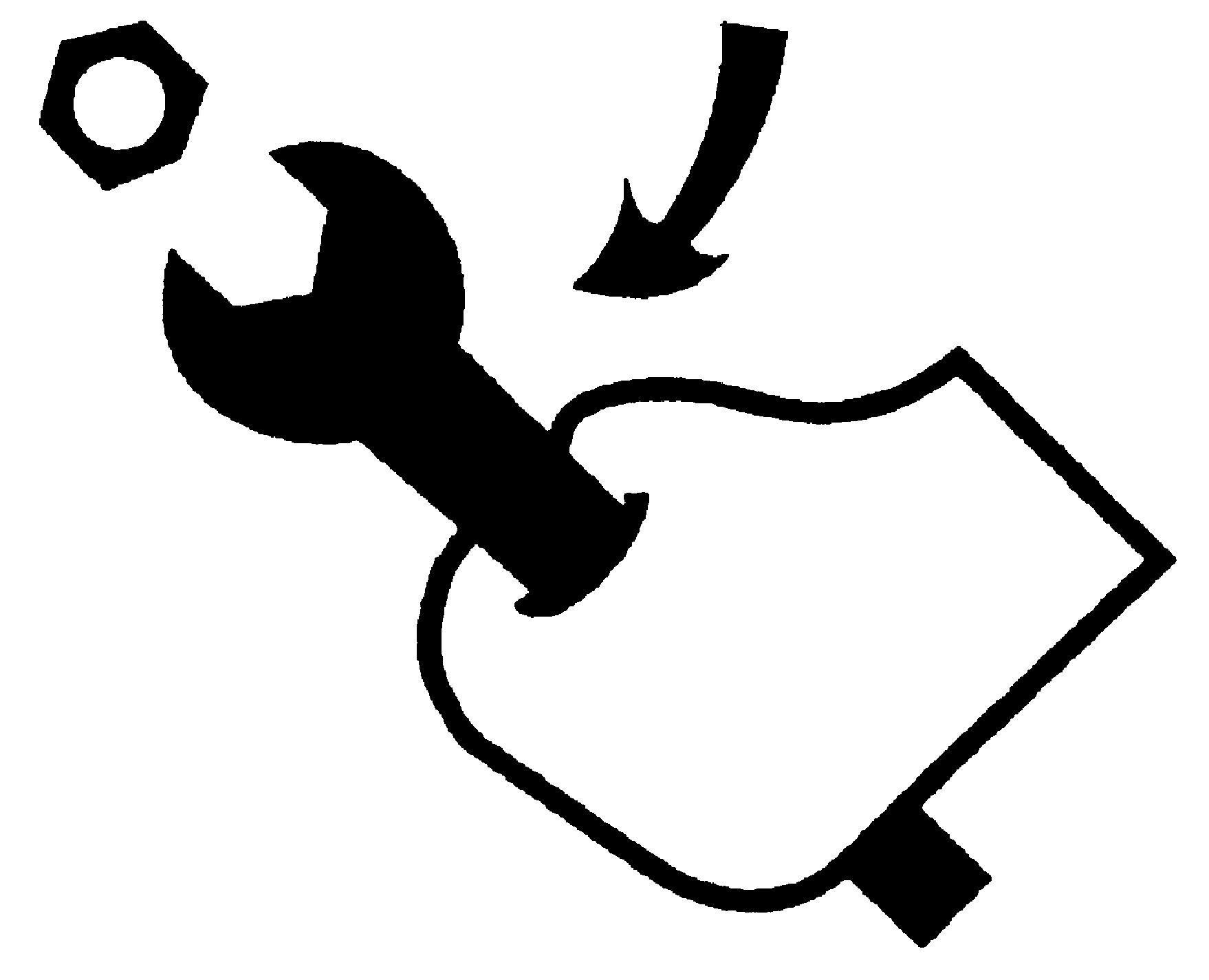
Place some wedges under the wheels so as to prevent the machine from moving. Unauthorized modifications of the machine can cause serious injuries. Do not carry out any modification on this machine without obtaining prior authorization from your Dealer. Any modification carried out must be in conformity with the machine’s technical specifications and must conform to current safety regulations. Do not carry out any welding operation on the machine without prior authorization from your Dealer. Some of the machine’s components are subject to type approvals. It is mandatory when replacing those components to ensure that they are in conformity with regulations. Hydraulic fluid or grease under pressure which penetrates the skin can cause serious injury. Take the necessary safety precautions (protective clothing and face and hand protection) to prevent all such risks. In addition, before handling these products, read the manufacturer’s specific instructions for their use. If hydraulic fluid penetrates the skin a doctor must be called immediately. When carrying out a welding operation on the machine, as authorized by the manufacturer and in accordance with his specifications, disconnect the electric system by means of the battery master switch, connect the welding set earth lead to the component on which the welding is to be carried out (never connect the ground lead to a hydraulic system component) and disconnect the electric cables of the motor control unit (in case of electronic motors). A burst tyre can cause serious injury. Regularly check the condition of tyres and always observe the inflation pressures defined in accordance with the type of tyre and ground conditions. When checking the tyre pressure or during an inflation operation, never stay in front of the tyre but always keep to the tread side. Always use an inflation cage when the wheel is removed from the machine. Keep all other persons away from the area. Never weld near a tyre. It is essential to remove the tyre before any welding operation. Take the necessary safety measures to protect your face when using compressed air. The machine’s structure is in conformity with the FOPS and ROPS protection standards. Any modification (drilling, welding, etc.) may cause that conformity to be invalidated.
O-RING FLAT FACE SEAL FITTING
O-RING FLAT SEAL FITTING TORQUE VALUES Nominal Dash size Thread size (inch)
Swivel nut torque O.D. (inch) Tube (mm) lbf·ft Nm 0.250 0.375 0.500 0.625 0.750 0.875 1.000 1.250 1.500 6.35 9.52 12.70 15.88 19.05 22.22 25.40 31.75 38.10 -4 -6 -8 -10 -12 -14 -16 -20 -24 9/16-18 11/16-16 13/16-16 1-14 1 3/16-12 1 3/16-12 1 7/16-12 1 11/16-12 2-12 12 18 37 51 75 75 105 140 160 16 24 50 69 102 102 142 190 217
MINIMUM HARDWARE TIGHTENING TORQUES lfb·ft (Nm)
INCH HARDWARE AND LOCKNUTS SAE GRADE 2 SAE GRADE 5 SAE GRADE 8 LOCKNUTS
Nominal Size Unplated or plated silver
Plated with zincchrome gold Unplated or plated silver
Plated with zincchrome gold Unplated or plated silver
Plated with zincchrome gold Gr.B with Grade 5 bolt Gr.C with Grade 8 bolt Nominal Size
1/4 55* (6.2) 72* (8.1) 86* (9.7) 112* (13) 121* (14) 157* (18) 61* (6.9) 86* (9.8) 1/4 5/16 115* (13) 149* (17) 178* (20) 229* (26) 250* (28) 324* (37) 125* (14) 176* (20) 5/16 3/8 17 (23) 22 (30) 26 (35) 34 (46) 37 (50) 48 (65) 19 (26) 26 (35) 3/8 7/16 27 (37) 35 (47) 42 (57) 54 (73) 59 (80) 77 (104) 30 (41) 42 (57) 7/16 1/2 42 (57) 54 (73) 64 (87) 83 (113) 91 (123) 117 (159) 45 (61) 64 (88) 1/2 9/6 60 (81) 77 (104) 92 (125) 120 (163) 130 (176) 169 (229) 65 (88) 92 (125) 9/16 5/8 83 (112) 107 (145) 128 (174) 165 (224) 180 (244) 233 (316) 90 (122) 127 (172) 5/8 3/4 146 (198) 189 (256) 226 (306) 293 (397) 319 (432) 413 (560) 160 (217) 226 (306) 3/4 7/8 142 (193) 183 (248) 365 (495) 473 (641) 515 (698) 667 (904) 258 (350) 364 (494) 7/8 1 213 (289) 275 (373) 547 (742) 708 (960)773 (1048)1000 (1356) 386 (523) 545 (739) 1
Nominal Size Unplated Plated with zinc-chrome Unplated Plated with zinc-chrome Unplated Plated with zinc-chrome
METRIC HARDWARE AND LOCKNUTS CLASS 5.8 CLASS 8.8 CLASS 10.9 LOCKNUT CL.8 with Class 8.8 bolt M4 15* (1.7) 19* (2.2) 23* (2.6) 30* (3.4) 33* (3.7) 42* (4.8) 16* (1.8) M6 51* (5.8) 67* (7.6) 79* (8.9) 102* (12) 115* (13) 150* (17) 56* (6.3) M8 124* (14) 159* (18) 195* (22) 248* (28) 274* (31) 354* (40) 133* (15) M10 21 (28) 27 (36) 32 (43) 41 (56) 45 (61) 58 (79) 22 (30) M12 36 (49) 46 (63) 55 (75) 72 (97) 79 (107) 102 (138) 39 (53) M16 89 (121) 117 (158) 137 (186) 177 (240) 196 (266) 254 (344) 97 (131) M20 175 (237) 226 (307) 277 (375) 358 (485) 383 (519) 495 (671) 195 (265) M24 303 (411) 392 (531) 478 (648) 619 (839) 662 (897) 855 (1160) 388 (458)
NOTA: there is no note on the page that * indicates lb·in and not lb·ft.