15 minute read
PROPORTIONAL CONTROL SOLENOID VALVE


Disassembly
For disassembly, follow the steps below. For assembly, follow the same procedure as for removal in the reverse order.
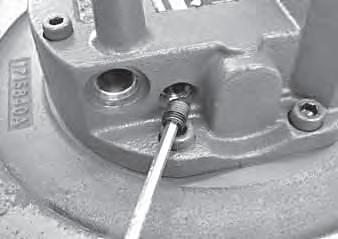
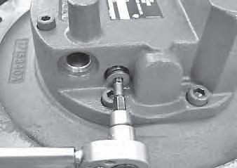
1. Take out the bolts and remove the proportional control solenoid valve.
Bolt: 6.9 ±1 N·m
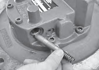
2. Remove the O-ring from the proportional control solenoid valve (1).
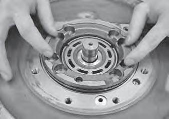
• Do not disassemble the sleeve (2) that is united with the solenoid (4) with the retaining ring (3).
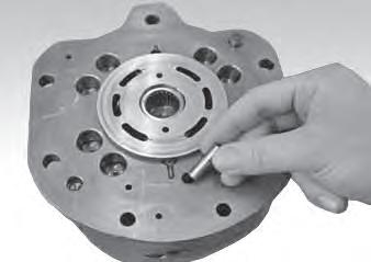
• Make sure that the spool (5) moves a little if pushed from the sleeve (2) end.
Inspection and adjustment
Checking the parts Part Criteria Action
Coil assembly
• When the solenoid is burned, short-circuited, or has a wire break
• Replace
• Wiring short-circuit or wire break
• Scratches, rust, or corrosion at the sliding parts with the spool
• Scratches, rust, or corrosion of the seal part in contact with the O-ring
• Replace
• Replace Body
• Replace
• Other damage considered to impair the normal functions
• Scratches on the outer circumference that easily catch a fingernail
• Replace
• Replace Spool
• Repair or replace Spring
O-ring
• Movement is not smooth
• Rust, corrosion, deformation, breakage, or other notable damage
• Replace
• Replace
Cylinders
Construction
Arm cylinder
Bucket cylinder
1. Piston packing
2. Rod packing
3. Dust seal
4. Backup ring
5. Backup ring
6. O-ring
7. O-ring
8. O-ring
9. Tube
10.
11. Piston rod
12. Bushing
13. Rod cover
14. Bushing
15. Cushion seal
16. Spacer
17. Stopper
18. Piston
19. Wear ring
20. Ball
21. Set screw
22. Cushion bearing
23. Washer
24. Screw
25. Cushion bearing
26. Grease nipple
27. Grease nipple
28. Dust seal
1. Piston packing
2. Rod packing
3. Dust seal
4. Backup ring
5. O-ring
6.
7.
8. Bushing
9. Tube
10. Bushing
11. Rod cover
12. Piston
13. Packing hoider
14. Wear ring
15. Snap ring
16. Bushing
17. Ball
18. Set screw
19. Dust seal
20. Grease nipple
Special tools
Unit: mm
Installation jig B
Quantity: 1
Material: SS41
Abcdef
Arm49.036.5105.01560
Bucket44.034.5105.01555
Sliding jig C
Quantity: 1
Material: STKM13C
ABCDE
Arm15.765.5634525
Bucket15.765.5634525
Fitting jig D
Quantity: 1
Material: Nylon
ABC
Arm706860
Bucket706860
Corrective jig E
Quantity: 1
Material: STKM13C
Arm8065
Bucket8065
This chapter describes mainly the procedure for the arm cylinder. When disassembling/assembling the cylinder, check its construction by referring to the construction diagram shown on the preceding page.
Disassembly
Cylinder assembly
1. Secure the cylinder horizontally by holding the clevis of the tube with a vice and placing a wooden support under the other end.
2. Drain out the remaining hydraulic oil in the cylinder.
• Move the piston rod slowly to prevent the hydraulic oil from spraying out.
3. Disengage the anti-rotation lock of the rod cover.
• Since the anti-rotation lock is built into the cylinder tube, take care not to damage the tube when disengaging the lock.
4. Loosen the rod cover.
• The piston rod should be pulled out approx. 200 mm beforehand.
• Cover the piston rod to prevent damage to it.
5. Take out the piston rod assembly from the tube.
• Pull it straight so as not to damage the sliding surface.
Piston rod assembly
1. Secure the piston rod assembly horizontally.
2. Remove the piston.
<Arm cylinder> a. Take out the set screw (1) and remove the ball (2). b. Remove the piston (3) and the cushion bearing (4). c. Remove the screw (5). d. Remove the cushion bearing (6).
• The set screw (1) is caulked in two points with a punch. Remove such parts by using a hand drill.
<Bucket cylinder> a. Take out the set screw (1) and remove the ball (2). b. Remove the piston (3).
• The set screw (1) is caulked in two points with a punch. Remove such parts by using a hand drill.
Piston
1. Take out the wear rings (10) and remove the piston packing (11).
• Stretch open the wear ring far enough to disengage it from the piston and pull it out in the direction of the shaft.
• Cut off the piston packing or take it out by using a flat-bladed screwdriver.
Rod cover
1. Remove the O-rings (20) and (21) from the outer diameter of the rod cover, and then remove the backup ring (22).
Remove the O-ring (23) and the backup ring (24) from the rod cover outer circumference (only for arm cylinder).
2. Remove the cushion seal (only for arm cylinder) and the rod packing.
<Arm cylinder> a. Remove the stopper (30) and the spacer (31). b. Remove the cushion seal (32). c. Remove the rod packing (33). d. Remove the backup ring (34).
<Bucket cylinder> a. Remove the snap ring (35) and the packing holder (36). b. Remove the rod packing (37).
3. Remove the dust seal (26).
• Tap alternately on several points around the inner circumference of the metal ring, gradually pushing the seal out.
Clevis
1. Remove the dust seals from the tube and piston rod.
2. Remove the bushing.
• Pull out the bushing by using a press with a supporting metal plate (27).
Assembly Clevis
1. Press-fit the bushings (28) into the piston rod and tube by using the installation jig B.
Rod cover
1. Install the rod packing and the cushion seal (only for arm cylinder).
<Arm cylinder> a. Install the backup ring (34). b. Install the rod packing (33). c. Install the cushion seal (32). d. Install the spacer (11) and the stopper (30).
• Be sure to install the rod packing in the correct direction.
<Bucket cylinder> a. Install the rod packing (37). b. Install the packing holder (36) and the snap ring (35).
• Be sure to install the rod packing in the correct direction.
2. Install the dust seal (26).
• For the dust seal with a metal ring around the perimeter, use a supporting metal plate (30) to install it.
3. Install the backup ring (22) and the O-rings (20) and (21).
Install the backup ring (24) and the O-ring (23) (only for arm cylinder).
• The cut portions of the backup rings should overlap correctly.
Piston
1. Install the O-ring (34).
• If the O-ring is twisted after being fitted, correct it.
2. Cover the piston with the sliding jig C, then using the fitting jig D, insert the slipper ring (35) rapidly.
3. Correct the shape of the slipper ring (35) using the corrective jig E, as its diameter has been extended at installation.
4. Install the wear ring (10).
• Stretch open the wear ring (10) far enough to install it on the piston from the direction of the shaft.
Piston rod assembly
1. Insert the rod cover assembly on the piston rod.
2. Install the piston unit.
<Arm cylinder> a. Install the cushion bearing (4) on the piston rod. b. Install the piston (3) on the piston rod, and then tighten the piston.
Piston: 528 N·m c. Insert the ball (2), tighten the set screw (1) and caulk at two points with a punch.
Set screw: 6.8 N·m d. Install the cushion bearing (6). e. Install the washer and the screw (5).
Screw: Loctite 648
Screw: 31.4 N·m
<Bucket cylinder> a. Install the piston (3) and tighten it.
Piston: 460 N·m b. Insert the ball (2), tighten the set screw (1) and caulk at two points with a punch.
Set screw: 6.8 N·m
Cylinder assembly
1. Secure the tube horizontally, and insert the piston rod assembly into the tube.
• When inserting, align the center of the piston rod with the center of the tube. Insert the assembly straight so as not to damage the seal.
Unit: N·m
Arm cylinder294
Bucket cylinder294
Inspection and adjustment
Inspection after disassembly
Clean each part thoroughly with cleaning oil, then carry out the following checks. When a cylinder has been disassembled, replace all the seals with new ones.
1. Piston rod
• Replace the rod if there are cracks.
• If the threads are damaged, repair them or replace the rod.
• If the plating layer of the plated portion is broken, rusted or scratched, replace the rod.
• If the rod is bent more than the limit of 1 mm in 1 m, replace it. (For the measurement method, refer to the figure on the right.)
• If the inner diameter of the clevis bushing is worn, replace the bushing.
Measuring the bend a. Support the portion of the rod with the same diameter at both ends on V-blocks. b. Set a dial gauge at the center between the two blocks. c. Rotate the rod and take a reading of the maximum and minimum run-out indicated by the dial gauge. If the bending of the rod is within the above limit, yet is bent a lot in a small distance so that it will not move smoothly, replace the rod if it makes a squeaking sound in the operation test after reassembly or if it catches during movement.
2. Tube
• If there are cracks in the welded portion, replace the tube.
• Replace the tube if the inside surface is scratched or if it leaks hydraulic oil.
• If the inner diameter of the clevis bushing is worn, replace the bushing.
3. Rod cover
• If the bushing inner diameter is worn and the clearance with the piston rod is greater than 0.25 mm, replace the bushing.
• If the inside surface of the bushing is scratched, and the scratches are deeper than the depth of the coating layer, replace the bushing.
Inspection after assembly No load operation test
1. Place the cylinder in a horizontal position with no load.
2. Apply gentle pressure alternately to the ports at both ends, operating the piston rod 5 or 6 times.
3. Make sure there is no abnormality in the operating condition.
Leak test
External leak
1. Apply test pressure for 3 minutes each to the retraction side and the extension side.
2. Make sure there are no abnormalities such as external leakage or permanent deformation, etc. in the rod seal, the rod cover mount, or in any welded portion.
Internal leak
1. Disconnect the extension side hose.
2. Apply test pressure to the retraction side for 3 minutes.
3. Measure the amount of oil that has leaked from the extension side.
• The amount of leakage should be 1 mL/3 min or less.
Bleeding air from the hydraulic cylinder
Bleed the air out of the cylinder when the cylinder is removed or when the hydraulic piping, etc. is disconnected.
1. Start the engine and let it idle for approximately 5 minutes.
2. With the engine running at slow speed, extend and retract the cylinder 4 or 5 times.
• Move the piston rod to a position 100 mm before the end of the stroke, being careful not to relieve air.
3. With the engine at top speed, repeat the operation in (2), then with the engine running at slow speed, move the piston rod to the stroke end to relieve air.
Travel Motor
Special tools
The part numbers contained in the “Disassembly and Assembly” section of this manual correspond to the numbers listed in the construction diagram. Work should be performed by referring to the diagram, as necessary.
Disassembly
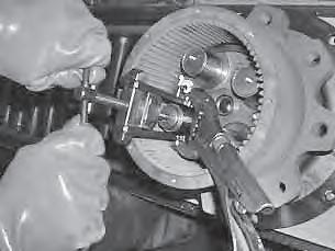
Reduction gears
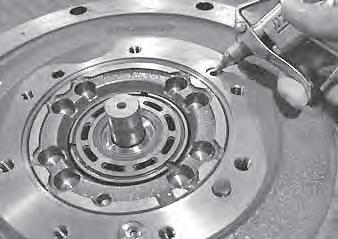
1. Take out the plugs and drain out the gear oil.
2. Take out the bolts and remove the cover (3).
• If it is hard to remove, lightly tap the side of the cover with the rubber hammer.
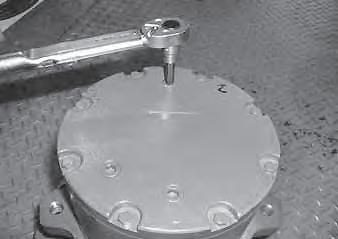
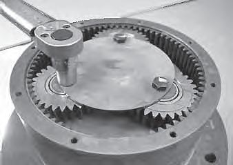
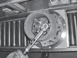
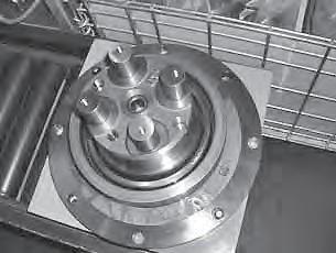
3. Take out the bolts and remove the thrust plate (10).
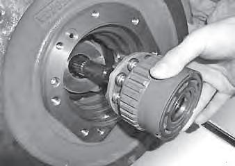
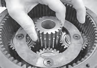
4. Take out the sun gear (5), and remove the planet gears (7) and the carrier (4).
• Remove the planet gears together with the needle bearing (15).
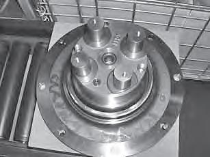
5. Take out the screws and remove the thrust plate (11).
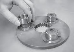
6. Remove the planet gear (8).
• Remove the planet gear together with the needle bearing (17).
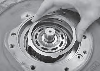
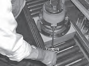
Hydraulic motor
1. Take out the cap screws, and then remove the valve body (24).
2. Remove the pins (20) and the valve plate (22) from the valve body (24).
3. Remove the springs (14) and the O-rings ((2), (3), (7)).
WARNING
In a work area where compressed air is used, metal fragments or other objects could scatter in the air. Wear protective gear such as goggles and a protective face mask.
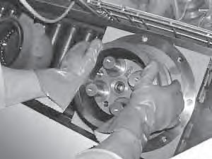
• Insert compressed air into the parking brake release port (A) of the flange holder, and then remove the brake piston.
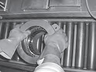
5. Remove the center discs (15) and the friction discs (16).
6. Remove the cylinder block assembly (12).
Important: Be sure not to damage the sliding surface.
7. Remove the shaft (11) and the swash plate (18).
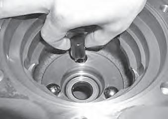
8. Remove the piston (19) and the balls (8).
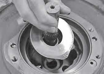
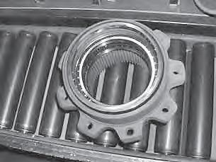
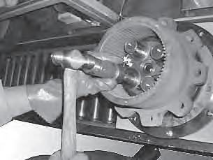
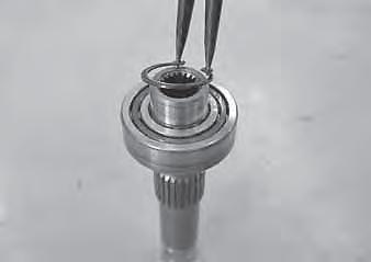
Floating seal
1. Remove the inner race (16).
• Use the jig (A) to hook the inner race, and then use the jig (B) to hold the jig (A) so that the inner race cannot be unhooked.
Jig manufacturer: Super tool
Jig (A): Armature bearing puller AB2
Jig (B): Grip pliers SG100
2. Remove the plugs.
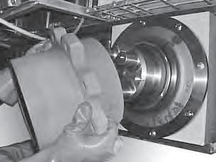
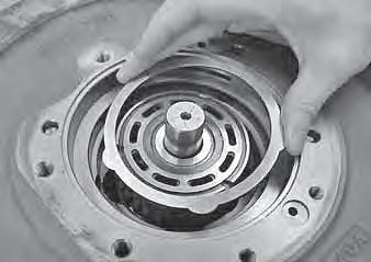
4. Remove the housing (2) from the flange holder (1). • Use the jig (D).
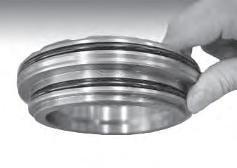
5. Remove the floating seals (18) from the housing (2) and the flange holder (1).
Assembly
Floating seal
1. Place the floating seal (18) in the housing (2).
• Apply gear oil on the O-ring.
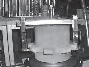
2. Place the guide jig (E).
3. Fit the floating seal (18) by pressing the guide jig (E) with the jig (F).
• Apply gear oil on the sliding surface.
Important:
• Be sure not to damage the sliding surface.
• The floating seal must be mounted horizontally.
4. Place the floating seal (18) in the flange holder (1).
• Apply gear oil on the O-ring.
5. Place the guide jig (G) in the flange holder (1).
6.
• Apply gear oil on the sliding surface. Do not apply grease.
Important:
• Be sure not to damage the sliding surface.
• The floating seal must be mounted horizontally.
•
10. Fit the plugs. Plug: 30 N·m
11. Install the inner races (16).
• Use the jig (I) and a hammer to install the inner races.
• After assembly, the dimension “X” must be between 0 and 1 mm.
Hydraulic motor
1. Install the oil seal (1).
• Press-fit the seal with its metal edge positioned upside.
• Grease the lip part of the oil seal.
2. Install the control piston (19) and the balls (8).
4. Install the shaft (11) and the swash plate (18).
• Apply hydraulic oil on the sliding surface of the swash plate.
5. Install the cylinder block assembly (12).
• Use the spline of the shaft as a guide.
6. Install the center discs (15) and the friction discs (16) alternately.
• The friction discs must be engaged with the spline of the cylinder block.
• Center disc: 4 discs
• Friction disc: 3 discs
7. Fit the O-rings to the brake piston (17).
• Lightly grease the O-rings.
8. Install the brake piston (17).
• Apply hydraulic oil on the sliding surface of the cylinder block.
• Be sure that no foreign matter is present in the cylinder block port.
• Gauge pin hole (A)
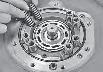
9. Install the springs (14) on the brake piston (17).
10. Install the O-rings (2, 3, 7) and the pin (20).
11. Install the valve plate (22) on the valve body (24).
• Grease the backside of the valve plate.
12. Install the pin (28).
13. Install the valve body (24) and fit the cap screw.
• The pin (28) must be fitted into the gauge pin hole (A) of the brake piston (17).
Cap screw 6 mm: 30 N·m
Cap screw 8 mm: 60 N·m
Reduction gears
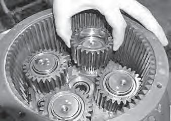
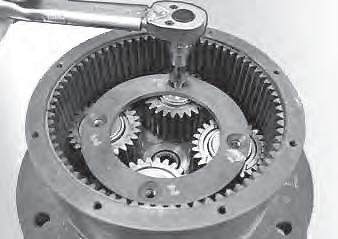
5. Install the planet gears (7) and the needle bearings (15) on the carrier (4), and then install them on the housing (2).
6. Install the sun gear (5).
7. Measure the depth “A” from the housing end face to the holder (pin).
8. Measure the dimension “B” of the cover.
9. The thrust plate must be such that its thickness “X” is 0.2 to 0.4 mm thinner than the thickness of “A” plus “B” measured above.
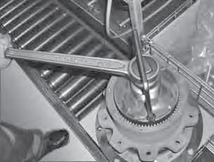
10. Install the thrust plate (10) and fit the screws. Bolt: 25 N·m
11. Install the cover and fit the bolts. Apply either Loctite #515 or ThreeBond #1215 to the cover surface on which the housing is mounted.
Bolt: 16 N·m
12. Add the gear oil through the plug hole, and attach the plug.
• Be sure to wrap seal tape around the plug.
• Gear oil to be added: 1 L
Plug: 22 N·m
Inspection and adjustment Use limit for parts
sliding
Valve plateSurface of the sliding part with the plunger No abnormal scratches, wear or seizure on the surface with a lapping tool (#1000) or replace the valve body and the spool together Spool Surface of the sliding part with the base plate
Valve bodySurface of the sliding part with the plunger No abnormal scratches, wear or seizure on the surface abnormal scratches, wear or seizure on the surface Center disc, friction disc Disc thickness Four center discs and three friction discs are worn to 13.5 mm or less
This “Troubleshooting” section describes the fault diagnosis and corrective actions mainly for hydraulic systems. The cause of the problem can be investigated by following the arrows in the chart shown at the beginning of each item.
Notes on troubleshooting and servicing
1. Do not disassemble the faulty part without first investigating the following.
a. Ask the user the following questions.
• The situation when the fault occurred.
• Any abnormalities or changes before the fault occurred.
• Any faulty parts other than the part in question.
• Any identical failure in the past b. Drive the machine yourself and confirm the faulty condition. c. Determine the cause of trouble based on the information obtained from the user and by driving the machine yourself. Also remember that once the machine has been disassembled, it is almost impossible to reproduce the conditions of the trouble, and so there will be no second chance to find out the true cause. Therefore be sure to find the true cause of the trouble before attempting disassembly.
• Determine if it is really faulty by referring to the performance criteria. Note that such determination may differ depending on the person.
Important: By operating the user’s machine, you could make a bad situation worse. Therefore, before driving the machine, always ask the user’s permission to do so.
2. When multiple causes are suspected, start with the simplest one.
3. Think why the trouble occurred and try to correct the root cause of the problem.
Overall Machine
No operation is possible. 1
1. Check the hydraulic oil level. Check the hydraulic oil tank level.
“4. Disassembly and assembly, Hydraulic oil tank”
When adding, use the same brand of oil currently being used.
“2. Service data, Fuel and lubricant table”
2. Check the hydraulic pump.
• Check the discharge pressure of the pumps P1 and P2 (HST pumps).
“2. Service data, Performance criteria” a. Disconnect the hose (2) of the discharging side from the pump. b. Start the engine. a. Turn on the starter switch. b. Lightly press down the protruding part on the solenoid end. c. Move the safety bar to turn on the proximity switch. d. If you feel vibration under your fingers when the spool is moved and the circuit is switched, the solenoid valve is normal. a. Disconnect the hose connecting the SUB valve and the pilot valve from the SUB valve. b. Fit the pressure gauge to the SUB valve and measure the pilot pressure.
• Check the pumps P3 and P4 (gear pumps).
• If the hydraulic oil flows out of the discharge port of the pump, it is normal. The pump will not operate if the pump coupling is faulty.
3. Check the fuse. Check the fuse in the circuit that operates the lever lock solenoid valve.
4. Check the proximity switch. The proximity switch (4) can be switched on by moving the safety bar (3) to the driving position. Use a tester to check if there is voltage in the lever lock solenoid (5).
• If there is voltage, the switch should be working.
5. Check the lever lock solenoid valve. Check the lever lock solenoid on the SUB valve.
6. Check the SUB valve.
• The SUB valve is normal if the measured pressures are:
Pilot valve (right): 3.1 MPa
Pilot valve (left): 2.0 MPa
All systems working, but insufficient power.
1 Check the hydraulic oil level Insufficient Add hydraulic oil.
Sufficient
2 Noise is generated by the hydraulic pump Yes Suction line faulty
Replace the seal tape, O-ring and hose. No Frothing in the tank
Action appropriate to the cause of the frothing.
3Check the line filter Clogged
Replace the filter element. No clogging
4Check the SUB valve Faulty
Repair or replace the SUB valve. Normal
5Hydraulic pump is faulty
Repair or replace the hydraulic pump.
1. Check the hydraulic oil level.
“4. Disassembly and assembly, Hydraulic oil tank” a. The lines for sucking the hydraulic oil b. Clogging in the suction filter
2. Noise is generated by the hydraulic pump. The noise is likely to be caused by cavitation in the pump, due to a faulty suction line. Check the following.
• Apply grease or oil on the suspected faulty sections and check for a change (check if air is being sucked).
3. Check the line filter. Remove the case and take out the filter element to check for any clogging.
4. Check the SUB valve. “5-5”
5. Hydraulic pump is faulty.
If the inside of the pump is excessively worn or damaged, it is likely that metal pieces are in the hydraulic oil. If this is the case, do the following.
• Replace the elements of the line filter and the spin filter.
• Replace the hydraulic oil or perform flushing.
• When replacing the hydraulic oil, clean the tank and the suction strainer.
“4. Disassembly and assembly, Hydraulic oil tank”
If the pump seal is damaged, replace it.
“4. Disassembly and assembly, HST pump”
Lift arm and bucket fail to move or are too slow.
1 Check the hydraulic pump P3 Faulty Repair or replace the hydraulic pump P3.
Normal
2 Check the main relief valve Faulty Repair or replace the main relief valve.
Normal
3Pilot valve is faulty Repair or replace.
1. Check the hydraulic pump P3. “5-4”
2. Check the main relief valve. Measure the relief pressure of the main relief valve.
• If the measured value is within the specifications, it is normal.
2. Service data, Performance criteria”
If the measured value is below the specifications, adjust it to the set value by gradually tightening the set screw.
• If the pressure does not become higher after 1/4 turns, the relief valve is faulty.
3. Pilot valve is faulty.