24 minute read
Chapter 8 SERVICE AND STORAGE GENERALINFORMATION


Warning
BEFORE performimg any service on the Telehandler, unless expressly instructed to the contrary, exercise the MANDATORYSAFETYSHUTDOWN PROCEDURE (Safety chapter). After service has been performed, BE SURE to restore all guards, shields and covers to their original positions BEFORE resuming machine operation.
When a problem occurs, don’t overlook simple causes such as an empty fuel tank. Check for leaks and broken connections. Make note of any specific problem symptoms, noises, etc. and contact your local Mustang dealer.
IMPORTANT: Always dispose of waste lubricating oils, anti-freeze and hydraulic fluids according to local regulations or take them to a recycling center for disposal. DO NOT pour them onto the ground or into a drain.
Dealer Services
NOTE: All service routines, with the exception of those described under the “Dealer Services” topic, are owner-operator responsibilities. All operator services described under the subtopics are also referred to on a decal located on the inside right side panel of the operator’s station. Refer to the LUBRICATION chapter of this manual for lubrication information.
NOTE: This SERVICE AND STORAGE chapter describes procedures to follow for making routine maintenance checks, adjustments and replacements. The majority of the procedures are also referred to in the MAINTENANCE chapter of this manual. For engine related adjustments and servicing procedures, be sure to refer to the engine manual provided.
Precautions
DO NOTperform any maintenance or repair without the owner’s prior authorization. Allow only trained personnel to service the machine.
Warranty repairs can only be done by a Mustang dealer. They will know what portions of the machine are covered under the terms of the Mustang Warranty and what portions are covered by other vendor OEM warranties.
The following areas of internal components service replacement and operating adjustments should only be attempted by (or under the direction of) an authorized MustangTelehandler dealer.
IMPORTANT: DO NOT service or repair major components, unless authorized to do so by your Mustang dealer. Any unauthorized repair will void the warranty.
Power Train Components
The engine and transmission are coupled directly to each other. All service routines, related to the internal components are precise and critical to proper power train operation. The axle differential and planetary ends are also sophisticated assemblies which require special know-how and tools for servicing.
IMPORTANT: If any area of power train componentry is suspected of faulty operation, contact your Mustang dealer for further assistance.
Hydraulic System Components
Valves, pumps, motors and cylinders are also sophisticated assemblies which require special know-how and tools for servicing. All cylinders are appropriately designed with particular strokes, diameters, checks and hose connection provisions unique to the machine application requirements. Aschematic (located at the end of this manual) can be used as a guide for service reference, as required.
Warning
Tilt, lift, extend and leveling cylinders have counterbalance valves. These valves keep hydraulic fluid from entering or exiting the cylinders while not being used, and are under extremely high pressure. Before removing one of these valves, you ARE REQUIRED to call your Mustang dealer or Mustang Service Department. Failure to do so may result in serious injury or death.
Internal service on any of these components should only be attempted by (or under the direction of) an authorized Mustang Telehandler dealer. Warranty repairs can only be done by a Mustang dealer. He will know what portions of the machine are covered under the terms of the Mustang warranty and what portions are covered by other vendor warranties.
Electricalcomponents
An electrical system schematic is provided which includes instrumentation, electrical components and switch connections. It is located at the end of this manual and can be used as a guide for service reference, as required.
Operator Services
Some of the operator-related services will require access to components located inside the superstructure under shields, hoods and covers. The chart on this page notes components accessed in each particular area.
Access To Components Chart
Axle (underside)
Engine Transmission (mid area)
Drive Shafts (underside)
Main Control Valve (rear)
Muffler (underside)
Air Cleaner (top front hood)
Battery
Radiator
Brake Valve (underside)
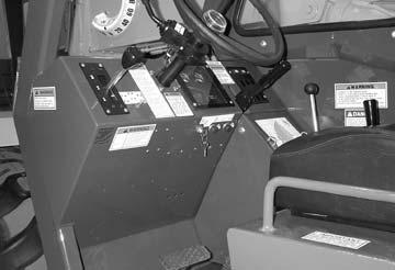
Travel Controls (dash area)
Boom Controls (right side)
Hydraulic Test Ports (dash)
Hourmeter (dash)
Switches/Indicators (dash)
Hydraulic Pump
Hydraulic Filter (Reservoir)
Misc. Hydraulic Valves
Air Conditioner (rear)
Heater (lower front)
Warning
DO NOT smoke or allow any open flames in the area while checking or servicing hydraulic, battery or fuel systems; all contain highly flammable liquids or explosive gases which can cause an explosion or fire if ignited. Wear a face shield when you disassemble spring-loaded components or work with battery acid. Wear a helmet or goggles with special lenses when you weld or cut with a torch.
When working beneath a raised machine, always use blocks, jack-stands or other rigid and stable supports. Wear appropriate protective clothing, gloves, shoes. Keep feet, clothing, hands and hair away from moving parts.
Always wear safety glasses or goggles for eye protection from electric arcs from shorts, fluids under pressure, and flying debris or loose material when the engine is running or tools are used for grinding or pounding.
NEVER weld on bucket, forks, boom, support frame or ROPS/FOPS without the consent of the manufacturer. These components may be made with metals that require special welding techniques, or with designs that do not allow weld repairs. NEVER cut or weld on fuel lines or tanks.
If repair welding is ever required, BE SURE to attach the ground (-) cable from the welder as close as possible to the area to be repaired. Also, remove battery positive (+) terminal connection before welding.
Block the wheels. Remove the ignition key. Remove only guards or covers that provide needed access. Wipe away excess grease and oil.
Excessively worn or damaged parts can fail and cause injury or death. Replace any cracked or damaged parts. Care should be taken to assure that all replacement parts are interchangeable with original parts and of equal quality.
Use care not to damage machined and polished surfaces. Clean or replace all damaged or painted-over plates and decals that cannot be read.
Warning
NEVER leave guards off or access doors open when the machine is unattended. Keep bystanders away if access doors are open.
Service Every 10 Hours or Daily
After servicing, check the work performed, no parts left over, etc. Install all guards and covers.
Check Fueltank Level
After operation each day, the fuel tank should be filled to prevent water from condensing in the tank. To fill, remove the filler cap and add fuel.
Adrain plug is provided in the bottom of the fuel tank for removing condensation and other foreign materials. Open the plug and allow water and fuel to drain into a container until only clear fuel is flowing from the tank.
Check Fuelfilter
Choose a clean, level work area. Make sure you have sufficient room, clearances, and adequate ventilation. Clean the walking and working surfaces. Remove oil, grease and water to eliminate slippery areas. Utilize sand or oil absorbing compound, as necessary, while servicing the Telehandler.
Before starting inspection and repair, move the machine onto a level surface, shut down engine, and release all hydraulic pressure. Always block the boom securely, or lower it to full ground contact. Place all controls in neutral.
NOTE: The fuel filter will require occasional replacement to maintain a clean and adequate fuel flow for maximum engine horsepower. The frequency of filter replacement will be determined by the cleanliness of available fuel, the care used in storing fuel supplies and the operating conditions in which the machine is used.
Small amounts of water can be drained from the fuel filter. The drain plug should be removed weekly to drain off water accumulation until clear fuel is flowing from the outlet.
Check Engine Oillevel
With the machine on level ground, and the engine stopped for ten minutes or more, slide open the side engine panel and remove the engine dipstick. Wipe it clean, re-insert it and remove to obtain a reading. If the oil level is down, or below the ADD mark, fill with the required amount of oil to bring the level to the FULL mark. See the LUBRICATION chapter for the type of oil to use.
Check Radiator Coolant Level
Warning
DO NOT remove the radiator cap when the engine is running hot or overheated. Coolant is extremely hot and under pressure and it can burn your skin. Allow sufficient time for the radiator to cool BEFORE relieving the pressure and removing the radiator cap.
will reduce the possibility of overfilling the hydraulic system, and also reduce potential injury due to hot fluid.
Remove the front cover from the front hood section. Loosen the filler cap to release pressure. Remove the filler cap and check the level on the dipstick. If the oil level is down, or below the ADD mark, fill with the required amount of oil to bring the level to the FULL mark. See the LUBRICATION chapter for the type of oil to use.
IMPORTANT: Be careful when removing the reservoir filler cap that no dirt or other foreign matter enters the hydraulic system. DO NOT OVERFILL.
Check Brake Reservoir Level
The brake booster master cylinder reservoir is under the operator’s compartment. The compartment panel tilts forward for access to the reservoir. Remove the reservoir caps to check the level. If low, fill to proper level with hydraulic brake fluid (Type DOT3) only.
With the machine on level ground, remove the radiator cap. If the coolant level is below the filler neck, add a low-silicate ethylene glycol base coolant mixed with quality water and supplemental coolant additives (SCAs) suitable for heavy duty diesel engines. See your engine manual for additional information. Replace the radiator cap securely.
NOTE: If the engine is operated with a loose radiator cap, the pressure bypass will not work and the engine will run hot.
Check Transmission Oillevel
The machine must be on level ground with the boom lowered and completely retracted. With the engine and transmission at operating temperature parking brake on, transmission in neutral and engine speed at low idle, remove the access cover to the transmission and hydraulic pump. Remove the dipstick and check the oil level. Add the required amount of oil to bring the level to the FULLmark. See the LUBRICATION chapter for the type of oil to use.
Check Hydraulic Oillevel
The machine must be on level ground with boom lowered and completely retracted. The fluid MUSTbe cool when checking the reservoir level. By doing this, you
Check Park Brake Handle
Check the tension when pulled. Adjust as necessary to a pull of 20 lbs (89 N).
Check Tire Pressures
Proper tire pressure should be maintained equally for all four tires to enhance operating stability and extend tire life.
When installing tires on the machine, be sure that all tires are of the same size and style. ALWAYS replace tires with the same size furnished as original equipment. Replacement tires must be purchased locally.
Check the tire pressure “cold”. All 12 ply tires should be inflated to 70 PSI (480 kPa).
NOTE:If the tires have been filled with water or calcium chloride for weight, a calcium chloride tire pressure gauge MUST be used to check the tire pressure.
When removing tires follow industry safety practices. Deflate completely prior to removal. After assembly of the tire onto the rim, use a safety cage or restraining device while inflating.
Check Wheelnut Torque
On new machines, or any time a wheel has been removed, re-torque until 450 ft-lbs (610 Nm) is maintained.
Warning
Inflating or servicing tires can be dangerous. Whenever possible, trained personnel should service and mount tires. To avoid possible death or serious injury, follow the safety precautions below:
1. BE SURE the rim is clean and free of rust.
2.Lubricate both the tire beads and rim flanges with a soap solution. DO NOT use oil or grease.
3.DO NOT place your fingers on the tire bead or rim during inflation. Use a clip-on tire chuck with a remote hose and gauge, which allows you to stand clear of the tire while inflating it.
4. NEVER inflate beyond 35 PSI (240 kPa) to seat the beads. If the beads have NOT seated by the time the pressure reaches 35 PSI (240 kPa), deflate the assembly, reposition the tire on the rim, relubricate both parts and reinflate. Inflation pressure beyond 35 PSI (240 kPa) with unseated beads may break the bead or rim with explosive force sufficient to cause death or serious injury.
5.After seating the beads, adjust the inflation pressure to the recommended operating pressure listed.
6.DO NOT weld, braze, or otherwise attempt to repair and use a damaged rim.
Check Instruments Operation
Allow the engine to warm up for about five minutes before beginning operation. Indicator lamps should be OFF and gauges should register normal readings. Tilt the frame from side to side with the frame leveling control and note the angle indicator movement.
Check Generalmachine Operation And Condition
Are any decals missing or damaged? Are all guards, shields and covers in place? Do all controls function smoothly and properly? Are there any abnormal vibrations or noises? Are any hose or fitting connections leaking? Is the engine exhaust color normal (light grey)?
Service Every 50 Hours or Weekly
Lubricate Grease Points
Refer to the LUBRICATION chapter of this manual for weekly grease fitting locations and other related details.
100 Hours (New Machine Only)
The following initial oil and filter changes should be made at this time on a new machine. Thereafter these changes should be made at the regular maintenance schedule listed. Refer to those schedules for the necessary procedures.
Engine Oil & Filter( 250 Hours)
Transmission Oil & Filter(1000 Hours)
Hydraulic Oil Filter(1000 Hours)
Service Every 250 Hours
NOTE: Perform all other service requirements up to this point, as well as the following:
Change Air Filter Element
This air filter contains a single dry element. Wipe the outside of the body with a rag or cloth. Blow off excess dirt and dust with compressed air. Refer to illustration below.
1.Loosen the clamp ring and remove the dust cup. Remove the baffle. Wipe the cup and baffle completely clean. Reassemble the dust cup.
2.Remove the element wing bolt and slide out the element. Avoid knocking the element against the housing. Dirt accidentally transferred to the inside of the outlet tube will reach the engine and cause wear.
3.Wipe the entire inside of the main body and inlet cap screen.
Astreak of dust on the clean air side of the old element indicates a leakage problem. Be sure to remove the cause before installing a new element.
4.Inspect the new element for possible damage. Placing a bright light inside the element and inspecting the outside will show up any holes or tears. Discard the element if such damage appears.
IMPORTANT: NEVER use an element that is damaged. Severe engine wear and eventual failure can result if dirt gets through a hole in the element.
5.Install the element and reassemble the dust cup to housing. Be sure the large o-ring is in place between the dust cup and the main body.
NOTE: Keep spare elements on hand to eliminate down time.
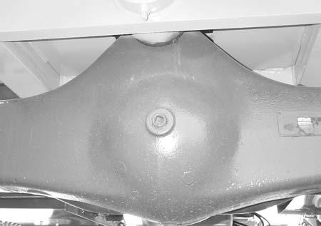
CHECK AXLE OILLEVELS Differential
NOTE: The Telehandler should be on a level surface for this procedure.
See illustration. Remove the check/fill plug (located on side opposite the drive shaft U-joint). If low, fill until oil overflows the hole. Replace the plug, wait 10 to 15 minutes and repeat the fill procedure. Continue this process until the differential is full. See the LUBRICATION chapter for the proper oil specification. Replace the plug.
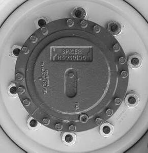
Planetary Hubs
NOTE: The planetary hubs can be checked without jacking up the machine.
See illustration. The planetary hubs have one plug each used for filling and draining. For checking the level and filling, position the wheel until the arrow points down. Remove the fill plug. If oil does not run out, add oil until it overflows. Check the remaining hubs the same way. Refer to the oil specifications found in the LUBRICATION chapter of this manual.

Change Fuelfilter
The frequency of filter replacement will be determined by the cleanliness of available fuel, the care used in storing fuel supplies and the operating conditions in which the machine is used.
NOTE: For proper replacement procedures refer to the engine manual for your machine.
After fuel filter replacement, bleed the air out of the fuel system following the procedures in the engine manual.
Warning
NEVER service the fuel system while smoking, while near an open flame, or after the engine has been operated and is hot.
Fuel Bleeding Procedures
When the fuel filter is removed and replaced, or the engine runs out of fuel, air must be bled from the system. Refer to the engine manual for proper bleeding procedures.
If the engine still will not start, consult your authorized engine dealer.
NOTE: Only an authorized engine dealer can perform warranty service on the engine.
Diesel Fuel Injectors
Whenever faulty or plugged injectors are indicated, see your authorized engine dealer.
Diesel Injection Pump Timing
Whenever injection pump timing, or other pump service is indicated by abnormal engine operation, contact your engine dealer.
Warning
Escaping diesel fuel under pressure can have sufficient force to penetrate the skin. Before applying pressure to the fuel system, BE SURE all connections are tight and lines and hoses are not damaged. Use a piece of wood or cardboard to search for suspected leaks. If injured by escaping fuel, see a doctor familiar with this type of injury at once or gangrene may result.
Change Engine Oiland Filter
Change the engine oil and filter using the following procedure:
1.With the engine warm, remove the crankcase drain plug. Some plugs are equipped with a magnet to gather metal particles. Completely clean and flush away all metallic filings from the plug and re-install it.
IMPORTANT: DO NOT discharge oil onto ground. Catch and dispose of per local waste disposal regulations.
2.The engine oil filter should be changed at every oil change interval. Remove and discard the disposible filter canister. Wipe the gasket sealing area of the block with a clean cloth.
IMPORTANT: Your OEM engine oil filters have special by-pass valves built in. Use only genuine OEM engine replacement filters.
3.Apply a thin coat of clean oil to the new oil filter gasket. Spin tighten. Refill the crankcase with new oil. Follow specifications in the LUBRICATION chapter for type and viscosity of new oil.
4.After new oil has been added, run the engine at idle speed until the oil pressure light is OFF. Check for leaks at the filter and drain plug. Re-tighten only as much as necessary to eliminate leakage.
Check The Battery
The battery furnished in the machine is a 12 volt, wetcell battery.
Handling Battery Safely
The top of the battery must always be kept clean. Clean the battery with a brush dipped in an alkaline solution (ammonia or baking soda and water). After the foaming has stopped, flush the top of the battery with clean water. If the terminals and cable connection clamps are corroded or have a buildup, disconnect the cables and clean the terminals and clamps with the same alkaline solution.
NOTE: The battery in this machine is warranted by the supplier. See the punch tag on the top of the battery for warranty information.
Warning
Explosive gas is produced while a battery is in use or being charged. Keep flames or sparks away from the battery area. Make sure battery is charged in a well-ventilated area.
NEVER lay a metal object on top of a battery as a short circuit can result.
Battery acid is harmful on contact with skin or fabrics. If acid spills, follow these first aid tips:
1.IMMEDIATELYremove any clothing on which acid spills.
2.If acid contacts the skin, rinse the affected area with running water for 10 to 15 minutes.
3.If acid comes in contact with the eyes, flood the eyes with running water for 10 to 15 minutes. See a doctor at once. NEVER use any medication or eye drops unless prescribed by the doctor.
4.To neutralize acid spilled on the floor, use one of the following mixtures: a.1 Pound (0.5 kg) of baking soda in 4 quarts (4 liters) of water. b.1 Pint (0.4 liters) of household ammonia in 4 quarts (4 liters) of water.
Whenever battery is removed from the unit, BE SURE to disconnect the negative (-) battery terminal connection first.
Jump Starting
If the battery becomes discharged or does not have enough power to start the engine, use jumper cables and the following procedure to jump-start the engine.
IMPORTANT: BE SURE that the jumper battery is also a 12 volt D. C. battery.
Warning
The ONLYsafe method for jump-starting a disharged battery is for TWO PEOPLE to perform the following procedure. The second person is needed for removing the jumper cables so that the operator does not have to leave the operator’s compartment while the engine is running. NEVER connect the jumper cables directly to the starter solenoid of either engine. DO NOT start the engine from any position other than the operator’s seat, and then ONLYafter making sure all controls are in “neutral.”
Closely follow the jump-start procedures, in the order listed, to avoid personal injury. In addition, wear safety glasses to protect your eyes, and avoid leaning over the batteries while jump-starting.
DO NOT attempt to jump-start the machine if the battery is frozen because this may cause it to rupture or explode.
1.Turn the keyswitches on both vehicles to OFF. Be sure that both vehicles are in “Neutral” and NOT touching.
2.Connect one end of the positive (+) jumper cable to the positive (+) battery terminal on the disabled machine first. DO NOTallow the jumper’s positive (+) cable clamps to touch any metal other than the positive (+) battery terminals. Connect the other end of the positive jumper cable to the jumper battery positive (+) terminal.
3.Connect one end of the negative (-) jumper cable to the jumper battery negative (-) terminal.
4.Make the final negative (-) jumper cable connection to the disabled machine’s engine block or frame (ground) -- NOTto the disabled battery negative post. If making the connection to the engine, keep the jumper clamp away from the battery, fuel lines, or moving parts.
NOTE: Twist the jumper cable clamps on the battery terminals to insure a good electrical connection.
5.Proceed to start the machine. If it does not start immediately, start the jumper vehicle engine to avoid excessive drain on the booster battery.
6.After the machine is started and running smoothly, have the second person remove the jumper cables (negative (-) jumper cable first) from the jumper vehicle battery, and then from the disabled machine, while insuring NOTto short the two cables together.
Allow sufficient time for the alternator to buildup a charge in the battery before operating the machine or shutting off the engine.
NOTE: If the battery frequently becomes discharged, have the battery checked for possible dead cell(s), or troubleshoot the electrical system for possible short circuits or damaged wire insulation.
Check Alternator And Fan Belt Conditon
Refer to the engine manual for proper belt tension adjustment and replacement procedures. If the belt shows wear or cuts, it should be replaced. Order replacement belt from your engine dealer.
Check And Torque Boom Leaf Chains
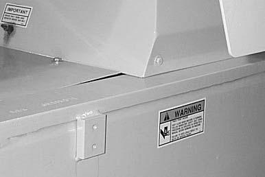
Inspect the leaf chains for wear and proper tension. Two of the chains are on the top front of the boom. A third chain is accessible from inside the rear of the boom (see boom illustration).
Run the boom out slowly to inspect. Conditions to look for include cracked or broken plates, protruding or turned pins, excessive wear. With a steel tape, measure 16 links of the strand that flexes over the sheaves. When the distance measures 12.375” (314 mm), the chain should be replaced. DO NOTrepair sections of a chain. Replace the complete chain.
Chain anchors and sheaves also require inspection for wear or broken fingers and worn flanges. If any chain has been replaced, operate under loaded conditions and re-check the torque. Adjust the chains per the following procedure.
Extend the boom to its maximum length. Then retract the boom slowly until the chain slack allows the chain to rest on the top of the boom. Torque the chains on the front of the boom to 30 ft-lb (40 Nm). Lubricate with 80/90 wt. oil.
Visually check for loose pad bolts. The bolts are torqued to 30 ft-lb (40 Nm). If the bolts are re-torqued at any time, Loctite thread lock must be re-applied to the bolts.
If the boom starts to chatter under load, grease the slide pads and wipe off the excess. If a top or side slide pad shows excessive wear, loosen bolts and insert shims to each side or top and bottom for even distribution of clearance. Re-apply Loctite® thread lock to the bolts and re-torque to 30 ft-lbs (40 Nm). Bottom slide pads should be replaced when the thickness is worn down to 3/8” (9.5 mm).
Service Every 1000 Hours
NOTE: Perform all other service requirements up to this point, as well as the following:
Change Transmission Oil And Filter
Chain Hookup Detail
Check Boom Slide Pads Wear And Clearance
The boom is equipped with special nylon low friction slide pads between the telescopic sections (see illustration). These are pre-greased and initially worn-in at the factory. Normally greasing is not required, except for maintaining a light film of grease on the pad tracking areas of the boom sections. An exception would be if a boom section has been replaced.
Operate the machine long enough to warm up the transmission oil. Shut down the engine. Access to filter and drain plug is from underneath the machine. Proceed as follows:
1.Remove the drain plug and drain out old oil. Replace the drain plug.
IMPORTANT: DO NOT discharge oil onto ground. Catch and dispose of per local waste disposal regulations.
2.Remove and discard the oil filter. Wipe the sealing surface on the transmission with a clean cloth. Apply a thin coat of clean oil to the new oil filter gasket. Spin tighten.
3.Refill the transmission with new oil as shown in the LUBRICATION chapter of this manual.
IMPORTANT: DO NOT OVERFILL! lf the oil level is too high, oil foaming, excessively high oil temperature and oil leakage at the seals could result.
4.Start and run the machine long enough for the oil to circulate and warm slightly. Recheck the level with the dipstick.
Change Radiator Coolant
Drain, flush and refill the cooling system as follows:
IMPORTANT: DO NOT discharge coolant onto ground. Catch and dispose of per local waste disposal regulations.
1.Loosen the radiator cap to its stop. This will release any system pressure. Remove the cap when all pressure is bled off.
Warning
Remove the radiator cap only when the engine is cool, or painful burns could result.
2.Open the radiator drain cock. Remove the water jacket drain plug from the engine block. When all coolant is drained, flush the system with clean fresh water. Allow the flush to drain completely.
3.Replace all drain plugs and tighten the radiator drain cock. Clean the cooling fins in the radiator with water pressure or steam.
IMPORTANT: Fill the cooling system with a low-silicate ethylene glycol base coolant mixed with quality water and supplemental coolant additives (SCAs) suitable for heavy-duty diesel engines. See your engine manual for additional information.
4.Inspect the radiator cap seal before installing it. Replace it if it appears defective. The 10 PSI (70 kPa) pressure cap and engine thermostat work in conjunction with each other to maintain proper engine cooling.
NOTE: Check the engine temperature gauge every minute or two after coolant has been changed. Air pockets can form and it may be necessary to refill the cooling system after a short period of use, as the air will naturally bleed out of the system.
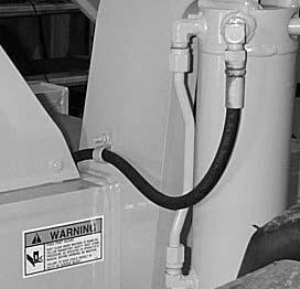
Change Hydraulic Return Filter Element
Warning
When servicing the hydraulic system, lower the boom to the ground.
This element is a cartridge type accessible from a housing on top of the hydraulic reservoir. Initial replacement is after the first 100 hours. See illustration. Remove the top cover of the housing. Remove the element and discard. Insert the new element into the housing and replace the cover.
CHANGE AXLE DIFFERENTIAL & PLANETARYOIL
Differentials
1.Remove the drain plug and drain out the old oil. Replace the drain plug (see illustration).
IMPORTANT: DO NOT discharge oil onto ground. Catch and dispose of per local waste disposal regulations.
2.Remove the check/fill plug. Fill the differential with oil as specified in the LUBRICATION chapter. When the oil overflows the check hole, replace the plug. Wait 10 to 15 minutes and repeat this process until the axle is full. Repeat this procedure with the other axle.
Axle Planetary Hubs
The hubs have one plug each used for draining and filling (see illustration).
with fresh oil as specified in the LUBRICATION chapter. When the oil runs out, install the drain/fill plug. Repeat this procedure on the three remaining hubs.
Check Exhaust System
Examine the muffler and tail pipe for possible holes. Re-tighten any loose clamps and make sure the manifold outlet gasket is not leaking.
Service Every 2000 Hours
NOTE: Perform all other service requirements up to this point, as well as the following.
Check Hydraulic System Relief Pressures
Pressure settings for relief valves are pre-set at the factory. Two test ports are provided on the dash front.
Before conducting any test port pressure checks, check the engine RPM. Engine speed must be 950 to 1000 RPM at idle and 2700 to 2750 RPM at high idle.
Steering Relief Pressure
Plug a 3000 PSI (206 bar) oil or liquid filled gauge into the test port. Cramp the steering fully to the right or left. The gauge should read 2200 PSI (152 bar).
Check Main Relief Pressure
1.Position the wheel until the arrow points to the left. Remove the drain/fill plug and allow the oil to drain out. Replace the plug.
IMPORTANT: DO NOT discharge oil onto ground. Catch and dispose of per local waste disposal regulations.
2.Re-position the hub so the arrow points down. Fill
With the gauge in the test port and the boom extended, retract the boom fully. The gauge should read 2850 PSI (196 bar).
Change Hydraulic Reservoir Oiland Strainer
Clean all dirt and debris from around the top of the reservoir, especially around the access cover. Refer to illustration and use the following procedure:
1.Remove the drain plug and drain out all used oil. Wash or blow off all particles collected on the magnetic drain plug.
IMPORTANT: DO NOT discharge oil onto ground. Catch and dispose of per local waste disposal regulations.
2.Remove the access cover and wash the inlet screen with clean solvent. Remove the sump filter strainer from the bottom inside of the reservoir. Wash it also. If the strainer has any damage, holes, etc., it should be replaced.
3.Flush out the bottom of the tank with clean hydraulic oil. Re-install all cleaned components and put the access cover back on the reservoir with a new gasket. Clean the filter/breather cap.
4.Fill the tank with fresh oil. Follow specifications found in the LUBRICATION chapter of this manual.
IMPORTANT: Hydraulic fluid and filters should be replaced any time contamination is present before the normally scheduled change.
Warning
Escaping hydraulic oil under pressure can have sufficient force to penetrate the skin. Before applying pressure to the hydraulic system, be sure all connections are tight and lines and hoses are not damaged. Use a piece of wood or cardboard to search for suspected leaks. If injured by escaping hydraulic oil, see a doctor familiar with this type of injury at once or gangrene may result.
Storage
If the Telehandler will not be operated for a long period of time, prepare and store it using the following procedure:
Before Storage
Perform the following prior to placing the machine in storage:
1Wash off the entire machine.
2.Lubricate all grease fittings as described in the LUBRICATION chapter of this manual.
3.Change engine oil as outlined in the SERVICE AND STORAGE chapter of this manual.
4.Apply grease to all exposed hydraulic cylinder rod areas.
5.Disconnect the battery cable clamps and cover the battery or remove the battery from the machine and store it separately.
6.If the ambient temperature (at any time during the storage period) is expected to drop below freezing, make sure the engine coolant is either completely drained from the radiator and engine block or that the amount of anti-freeze in it is adequate to keep the coolant from freezing. Refer to the separate engine manual provided for anti-freeze recommendations and quantities.
During Storage
1.About once each month, connect the battery and check all fluid levels to make sure they are at the proper level before starting the engine.
2.Start the engine and allow it to run until it warms up and then move the machine a short distance to help relubricate the internal parts. Run the engine until the battery has a chance to recharge and then shut it off.
IMPORTANT: If it is desired to operate the hydraulic cylinders at this time, BE SURE to wipe the protective grease (and any adhering dirt) from the cylinder rods prior to starting the engine. After operating, BE SURE to recoat the cylinder rods with grease if the machine is to be returned to storage.
After Storage
After removing the machine from storage and BEFORE operating it, perform the following:
1.Change engine oil and filter to remove condensation or other residues.
2.Wipe off grease from cylinder rods.
3.Lubricate ALLgrease fittings.
4.Review and re-familiarize yourself with all safety precautions as outlined in the SAFETYchapter of this manual.
5.Follow the starting and warm-up procedures as outlined in the OPERATION AND ADJUSTMENTS chapter of this manual.
Chapter 9
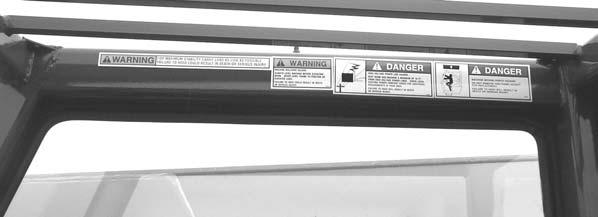
Decallocations
Generalinformation
Caution
ALWAYS read and follow the safety precautions on decals. Replace decals if they are damaged, or if the unit is repainted. If repainting, BE SURE that all applicable decals are affixed in their proper locations.
Decal locations information is provided to assist in the proper selection and application of new decals, in the event the original decals become damaged or the machine is repainted.
For correct replacement of decals compare the location illustrations to your machine before starting to refinish the unit. Check off each required decal using the illustration reference number to find the part number, description and quantity in the list. Refer to the appropriate illustrations for replacement locations.
New Decalapplication
Before applying the new decals, surfaces must be free from dirt, dust, grease and other foreign material. To apply a solid-formed decal, remove the smaller portion of the decal backing paper and apply this part of the exposed adhesive backing to the clean surface while maintaining proper position and alignment. Slowly peel off the other portion of the backing paper while applying hand pressure to smooth out decal surface. To apply a die-cut decal, first remove the backing paper. Then, properly orient and position the decal onto the clean mounting surface. After the decal is firmly applied and smoothly pressed down, remove the front covering paper.
Paint Finish
Use this list to order paint for refinishing:
420-354791(12oz.SprayCan)Yellow
420-35480OneQuartYellow
420-35498OneGallonYellow
420-361171(12oz.SprayCan)Gray
420-36229OneQuartGray
420-36230OneGallonGray
Decal Kits
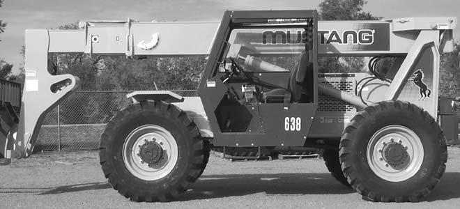
L500588Model638
NOTE: Decals may be purchased in kits or individually.
REF.DESCRIPTION638
NO.
01DANGER-ROTATINGFANL659244
02638-LEFTSIDE100153
03WARNING-PINCHPOINTL65927
04WARNING-JUMPSTARTL65933
05HORSE-LEFTSIDE100145
06WARNING-NORIDERS(1ea.)L65932
07QUICKATTACHDIAGRAM(1ea.)L65937
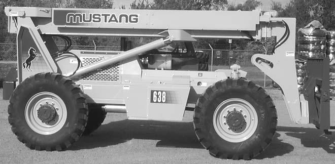
08MUSTANG-BOOMSIDE100258
09GRID-BOOMLEFTSIDE100141
10MUSTANG-FRONT100156
11HALFZONEMARKER(5ea.)L62583
12NO.“0”EXTENSIONMARKER(1ea.)L67718
NO.“1”EXTENSIONMARKER(1ea.)L67719
NO.“2”EXTENSIONMARKER(1ea.)L67720
NO.“3”EXTENSIONMARKER(1ea.)L67721
NO.“4”EXTENSIONMARKER(1ea.)L67722
NO.“5”EXTENSIONMARKER(1ea.)L67723
13PERSONNELINJURYL65928
14QUICKATTACHUNLOCKEDL66613
15GREASEDAILYL65920
REF.DESCRIPTION638 NO.
01DANGER-PERSONNELLIFTL65928
02WARNING-OPERATORL63690
03STEERSELECTL63618
04F-N-RSHIFTL68295
05STEERINGWHEEL2.0”DIA.100401
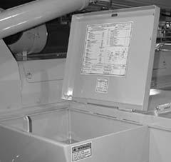
06HYDRAULICPRESSURESETTINGSL64643
07WARNING-PARKBRAKEL65925
08STANDARDCARRIAGELOADCHART100206
ROTATINGCARRIAGELOADCHART100207
BUCKETLOADCHART100208
TRUSSBOOMLOADCHART100210
WINCHLOADCHART100209
09ATTACHMENTCONTROL100400
10BOOMCONTROLL63631
11FRAMELEVELCONTROLL63311
12MADEINUSA137654
13IGNITION/START/HORNL68513
14WARNING-SEATBELTL65440
15OPERATORMANUALINSIDE137628
16WARNING-CARRYLOADLOW093475
17WARNING-MACHINELEVELL65930
18DANGER-HIGHVOLTAGEL65929
19DANGER-PANELINPLACEL65948
20WARNING-TRUSSBOOMTILTL66042
21WARNINGNORIDERSL65932
22BRAKEFLUIDLEVELL65934
23OPERATORMANUAL100359