31 minute read
SAFETY


Chapter 5
Indicators And Controls
Guards And Shields
Caution
Before operating the Telehandler, become familiar with and know how to use ALLsafety devices and controls. Know how to stop the machine operation before operating it. This Mustang machine is designed and intended to be used ONLYwith a Mustang Manufacturing Company attachment tool, or a Mustang approved accessory or referral attachment tool. Mustang Manufacturing Company cannot be responsible for safety if the machine is used with an unapproved accessory or attachment tool.
Whenever possible and without affecting machine operation, guards and shields are used to protect potentially hazardous areas. In many places, decals are also provided to warn of potential hazards and to display special operating procedures.
Warning
Read and thoroughly understand all safety decals on the Telehandler before operating it. DO NOT operate the machine unless all factory-installed guards and shields are properly secured in place.
Key Switch, Start and Horn Buttons
A1 - Key switch OFF: When the key is vertical in the keyswitch, power is disconnected from the battery to the control and instrument panel electrical circuits. Also, this is the only position in which the key can be inserted or removed.
A2 - Key switch ON: When the key is turned one position clockwise from the vertical (OFF) position, power from the battery is supplied to all control and instrument panel electrical circuits.


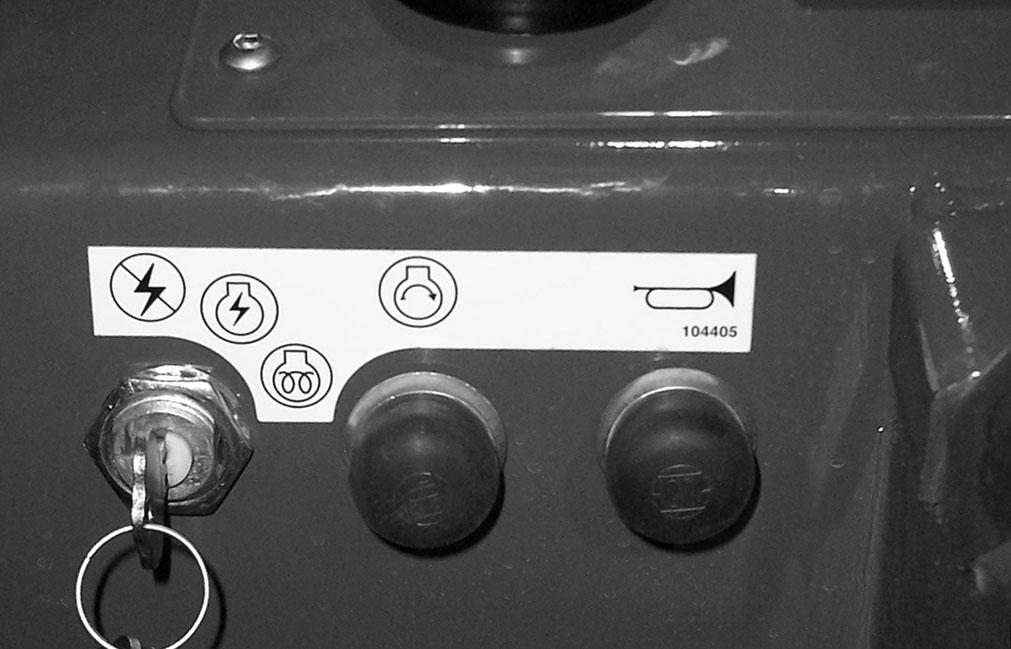
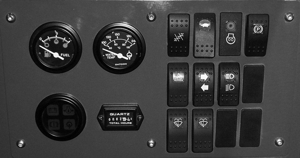
B - Electrical Engine Preheat: To activate the engine preheat, turn the keyswitch completely to the right against the spring load. The engine preheat indicator will light.
C - Start Button: With keyswitch in ON position, press the button to activate the starter. Release it as soon as the engine starts.
NOTE: If the engine requires repeated attempts to start, the key MUST be returned to the OFF position between starting attempts to prevent battery run down.
IMPORTANT: Do not use additional starting aids such as ether injection when using the electrical engine preheat.
D - Horn Button: With the keyswitch ON, press the horn button to activate warning sound.
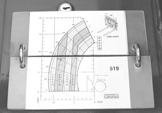
Load Zone Charts: A set of flip charts show lift height and reach limits relative to the load weight being handled with various attachment tools.
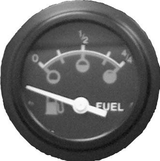
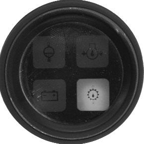
Fuel Level Gauge: The upper left gauge in the instrument panel, it indicates the amount of fuel remaining in the fuel tank.
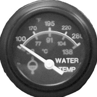
Coolant Temperature Gauge: The upper right gauge in the instrument panel, it indicates the temperature of the engine coolant. Under normal conditions, this gauge should indicate approximately 185°F (85°C).
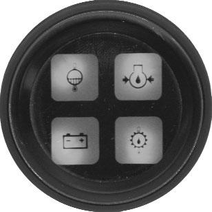
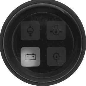
Lamp ClusterGauge: The lower left gauge in the instrument panel, it contains four indicator lamps. The functions of these lamps are as follows:
Engine Temperature Lamp: Located in the upper left quadrant of the lamp cluster gauge, this lamp lights when the engine coolant temperature is too high. During normal operation, with the engine running, this lamp should be off. During starting and when the engine is not running, this lamp will be on.
Engine Oil Pressure Lamp: Located in the upper right quadrant of the lamp cluster gauge, this lamp indicates whether the engine lubricating oil pressure is sufficient. During normal operation, with the engine running, this lamp should be off. During starting and when the engine is not running, this lamp will be on.
IMPORTANT: If this lamp comes on during normal operation with the engine running, stop the engine immediately! After allowing the oil to drain down for a few minutes, check the engine oil level. Maintain oil level between the marks on the dipstick.
AlternatorLamp: Located in the lower left quadrant of the lamp cluster gauge, this lamp indicates the condition of the electrical charging system. During normal operation, this lamp should be off. If the charge rate is too high or too low, this lamp will come on.
Hydrostatic Transmission Oil
Temperature Lamp: Located in the lower right quadrant of the lamp cluster gauge, this lamp lights when the transmission oil temperature is too hot. During normal operation this lamp should be off, indicating that the transmission oil is at the proper temperature.
IMPORTANT: If this lamp comes on during normal operation, a problem may exist in the hydrostatic transmission. Stop the machine immediately and investigate the cause of the problem!
Hourmeter: Located to the right of the lamp cluster gauge, it indicates the total operating time of the machine and should be used for keeping the maintenance log.
Top Row Switches and Indicator
Switches have graphic symbols to indicate function and effect. The following mode descriptions start with the first switch on the left.
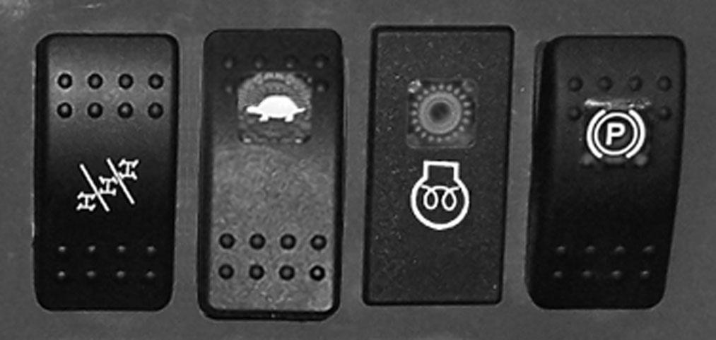
A- Steering Mode: This 3-position switch is used to select among the three steering modes. The upper position selects the 4-wheel steering mode. This mode selects all-wheel steering for making tighter turns, usually on a jobsite. The center position selects the 2wheel steering mode. This mode selects front wheel steering only, used for higher speed travel. The lower position selects the crab steering mode. This mode is used when a small amount of side shift is needed for picking or placing a load.
NOTE: The rear wheels are not self-centering. Make sure all wheels are in a straight-ahead position before changing the steering mode.
Any of the steering modes can be used in both forward and reverse travel. The operator should learn to anticipate changes in machine movement if the steering mode must be changed.
B - High/Low Speed: This switch is used to select the travel speed. Press the top of the switch to select low speed, used for load pickup and placement, or whenever low speed operation is desired. Press the bottom of the switch to select high speed, used for road travel.
IMPORTANT: Be sure machine is stopped before changing travel speeds.
C - Engine Preheat Indicator: When lighted this lamp indicates that the cold weather starting aid is in use.
D - Parking Brake: When the machine is parked, this switch should be pressed to actuate the parking brake mechanism in the front axle.
Warning
Unattended machine hazard. Activate parking brake switch and lower attachment tool to ground before leaving machine. An unattended machine can move or roll and cause death or serious injury to operator or bystanders.
Periodically check the parking brake operation to verify that it has adequate holding power. Always be sure the parking brake switch is off when resuming machine operation.
Middle Row Switches
Switches have graphic symbols to indicate function and effect. The following mode descriptions start with the first switch on the left.
NOTE: Some switches are optional and may not be on machine.
I and J - Wiper/Washer: The windshield and top window of the operator’s station are each equipped with a wiper and washer mechanism. Switch “I” operates the wiper and washer on the windshield; switch “J” operates the wiper and washer on the top window.
K and L- Option
Heater Controls
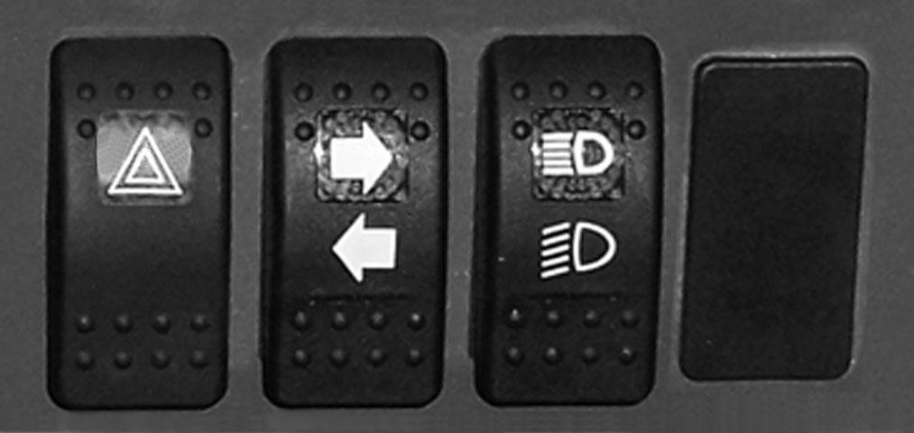
NOTE: Some switches are optional and may not be on machine.
E - Hazard: This switch can be activated to make the tail lights flash on and off in case the machine is stalled or temporarily stopped in a traffic area on the road or jobsite.
F- Turn Signal: This switch is used to indicate the direction of a turn with the tail lights. Press the right arrow for a right turn; press the left arrow for a left turn. Return the switch to the center position after the turn is completed.
G- Head Lights/Work Lights: Pressing the top of the switch will illuminate the lights mounted on the top of the operator’s station and the red tail lights for forward travel operations. Pressing the bottom of the switch will illuminate the lights at the end of the boom in addition to the lights on the operator’s station for additional lighting in working operations.
H - Option
Bottom Row Switches
Switches have graphic symbols to indicate function and effect. The following mode descriptions start with the first switch on the left.

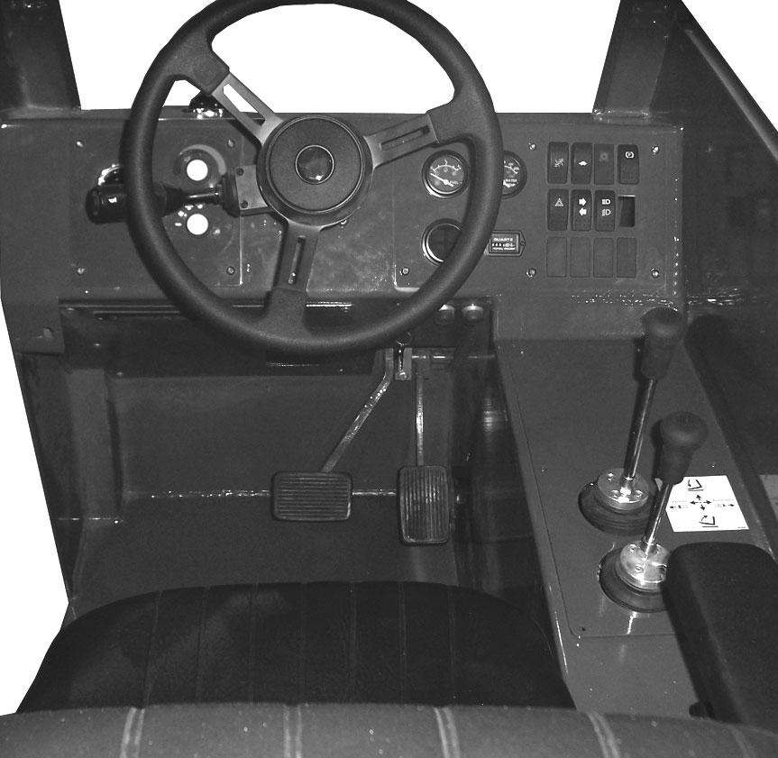
Temperature Control: This is the upper knob located to the left of the steering wheel. This knob is used to adjust the temperature output of the cab heater. Turning the knob clockwise will increase the temperature output.
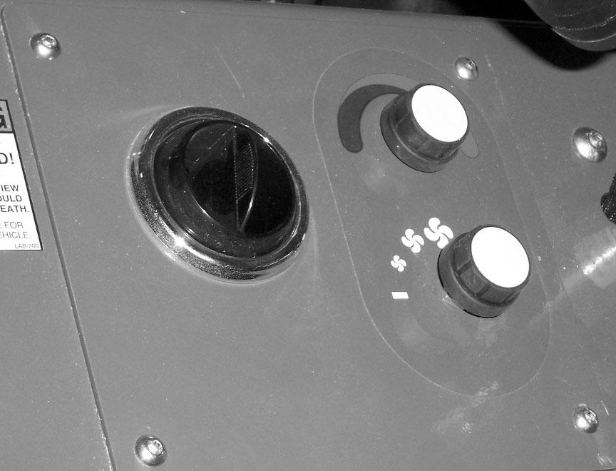
Fan Speed: This knob is located below the temperature control knob. Rotating the knob clockwise will increase the fan speed for increased air circulation.
Travel Lever
Located on the left side of the steering wheel column, this lever is used to change travel direction (forward or reverse).
Position “F” (FORWARD)
Position “N” (NEUTRAL)
Position “R” (REVERSE)
NOTE: The lever MUST be in N (Neutral) position before the starter will engage to start the engine.
IMPORTANT: Care should be taken when changing direction, because damage to the hydrostatic transmission can occur if shifting is forced or attempted at too high a speed. Allow machine speed to slow before any directional change is attempted.
NOTE: Backup alarm automatically sounds with travel lever in reverse.
Steering
The power steering system is designed to provide loweffort steering without shock reaction from the axle wheels to the steering wheel. Turn the steering wheel to the right or left to turn the machine in that direction.
Floor And Seat Area
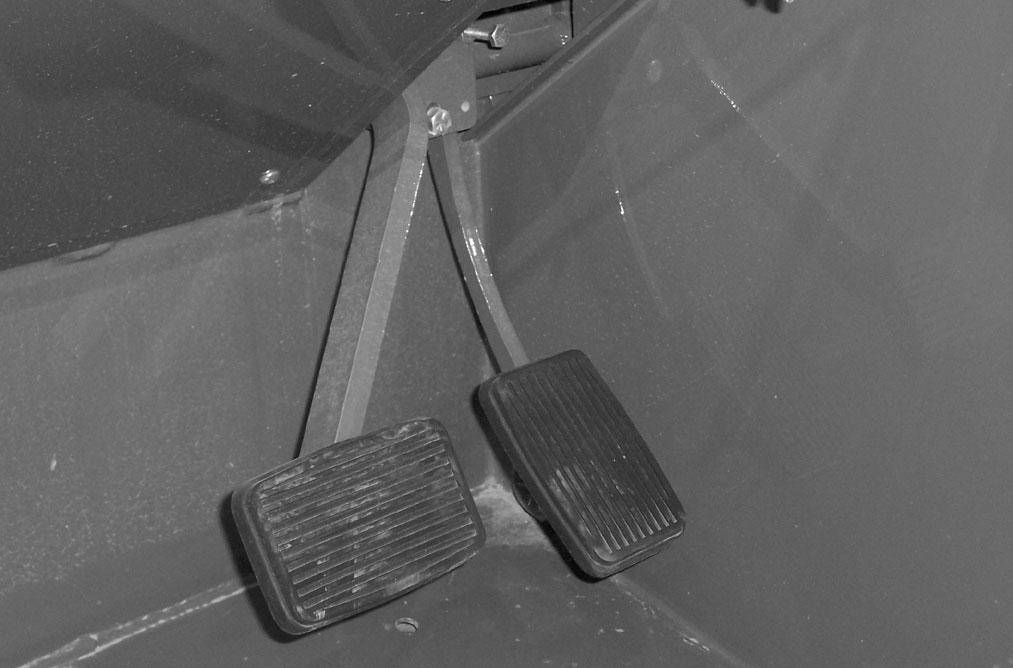
Throttle Pedal: This is right-foot operated and controls the engine speed to match increased power requirements. Pushing down on the pedal increases the RPM; letting up on the pedal decreases RPM.
Service Brake Pedal and Transmission Cut-off: Pressing the brake pedal hydraulically activates the internal braking mechanism in the front axle. During initial brake pedal travel and as the brake pedal is pressed farther, power to the transmission is progressively cut off. This allows faster engine speeds at slower operating speeds while maintaining power to the hydraulic system.
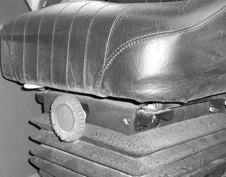
Seat Positioning: The seat is mounted on rails for forward and rearward repositioning to accommodate the operator’s size. Aspringloaded latch handle “A” under the front of the seat activates the adjustment mechanism.
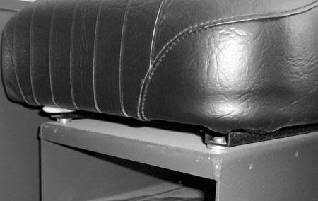
Suspension Seat (optional): In addition to the “A” latch handle for forward and rearward adjustment, this seat has a knob “B” under the front of the seat to adjust the suspension. Turn the knob to the right for a softer ride, and to the left for a firmer ride.
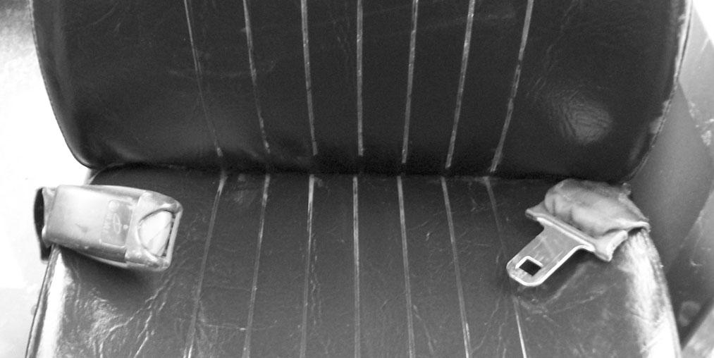
Seat Belt: This machine has a retractable seat belt. Grasp the belt on the left side of the seat pulling the belt over your lap and inserting the belt into the buckle on the right side of the seat until you hear it lock in place.
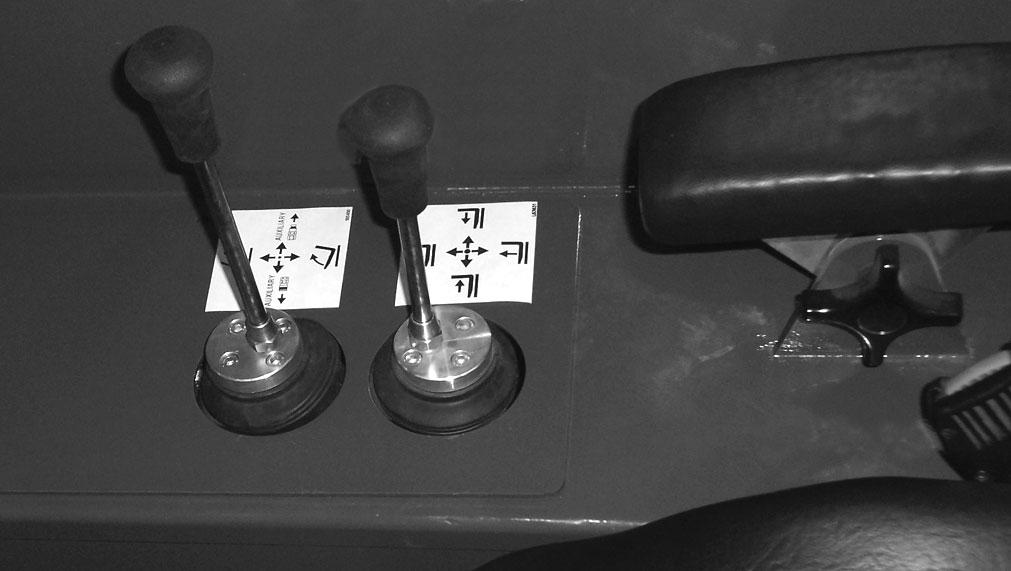
Right Side Panel
These controls are used to position the boom and attachment. Graphic symbols indicate the control actions.
Boom Control Joystick: This machine has a hydraulic-type telescopic boom. The boom section extends by means of a hydraulic cylinder inside the boom.
To extend the boom, move the joystick handle to the right; to retract the boom, move the joystick handle to the left. To raise the boom, move the joystick handle rearward; to lower the boom, move the joystick handle forward.
Auxiliary Hydraulics and Attachment
Warning
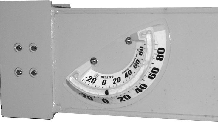
Use extreme caution when raising or extending the boom. The Telehandler MUST be within safe lifting parameters as indicated by the frame angle indicator. Loaded or empty, this machine can tip if not level.
ALWAYS place the transmission in neutral, set the parking brake and keep the service brake pedal fully depressed before raising or extending the boom.
NEVER exceed the specified lift and reach capacities of this machine. Serious machine damage or personal injury may result. Refer to the load charts in the operator’s station or this manual.
If a boom circuit hose bursts with the boom up, with or without a load, shut down the machine following the Mandatory Safety Shutdown Procedure (page 8). DO NOT attempt repairs. Call your Mustang dealer for assistance.
Attachment Tilt/Auxiliary Hydraulics Joystick: To tilt the attachment tool up, move the joystick handle rearward; to tilt the attachment tool down, move the joystick handle forward. When the operator tilts the attachment tool to a desired angle, that angle will be maintained as the boom is raised and lowered, extended and retracted, until a new angle is set.
Move the joystick handle to the left or right to operate the additional hydraulics required on some attachment tools.
Warning
The truss boom attachment tool should ONLY be used to lift and place loads when the machine is in a stationary position. DO NOT use to transport loads around the jobsite. This can cause the load to swing, resulting in either load dropping or machine tipover.
DO NOT tilt the truss boom back more than 45o from horizontal. Check the frame angle indicator before raising a load
Function Indicators
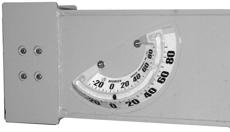
Frame Angle Indicator: Located in front of the operator on the ROPS upper cross tube, this indicator enables the operator to check if the Telehandler is at a safe angle for operation.
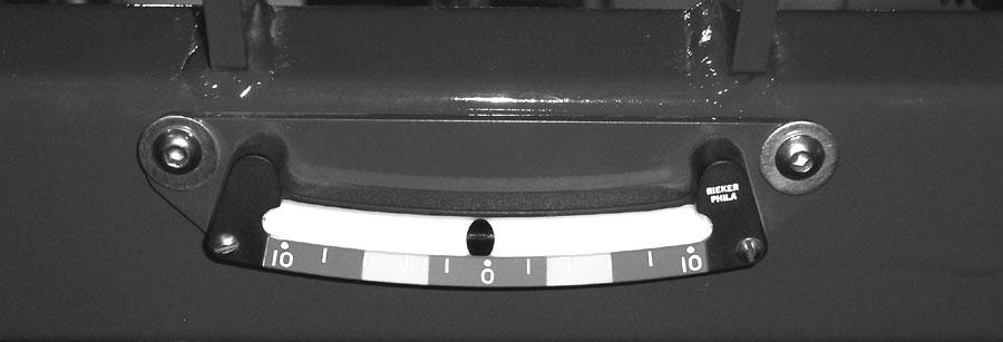
Boom Angle Indicator: Mounted on the left side of the outer boom, the position of the ball shows the angle of boom elevation relative to the ground.
Service And Safetyfeatures
The following indicators are for checking fluid levels. Engine Oil Level: The dipstick is located on the right side of the engine.
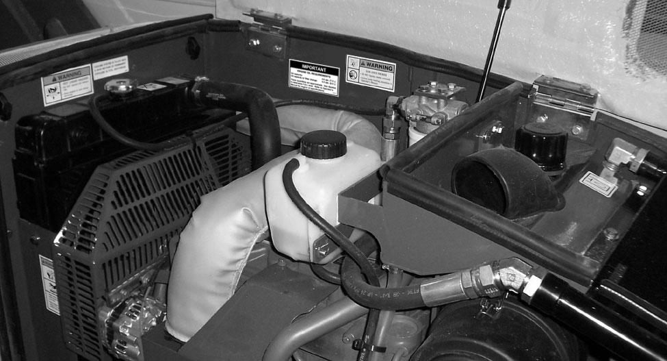
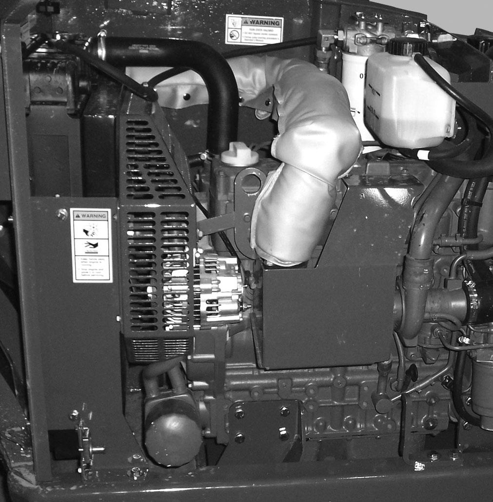
Hydraulic ReservoirOil Level and Fill Cap: The hydraulic oil level sight gauge is located under the engine cover on the firewall toward the front of the engine compartment. The hydraulic oil fill cap is located under the engine cover toward the front, just to the rear of the hydraulic oil cooler.
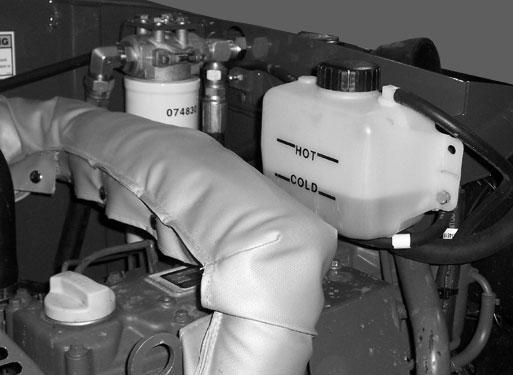
Coolant Level: The coolant recovery tank is located under the engine cover toward the front and above the engine.
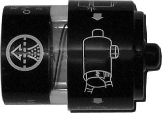
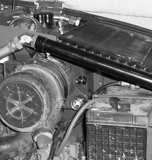
AirFilterRestriction Indicator: This indicator is located on the outlet of the air filter housing. (Refer to Checking and Changing Air Filter Element, page 49.)
Hydraulic Restriction Indicator: This indicator is located on the hydraulic filter assembly under the engine cover. (Refer to Checking and Changing Hydraulic Return Filter Element, page 48.)
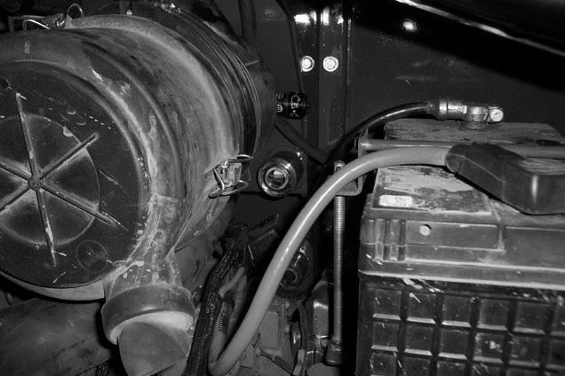
Battery: The battery is located under the engine cover toward the front of the engine compartment.
Backup Alarm: Located under the frame above the rear axle; it produces a loud warning sound whenever the machine is in reverse.
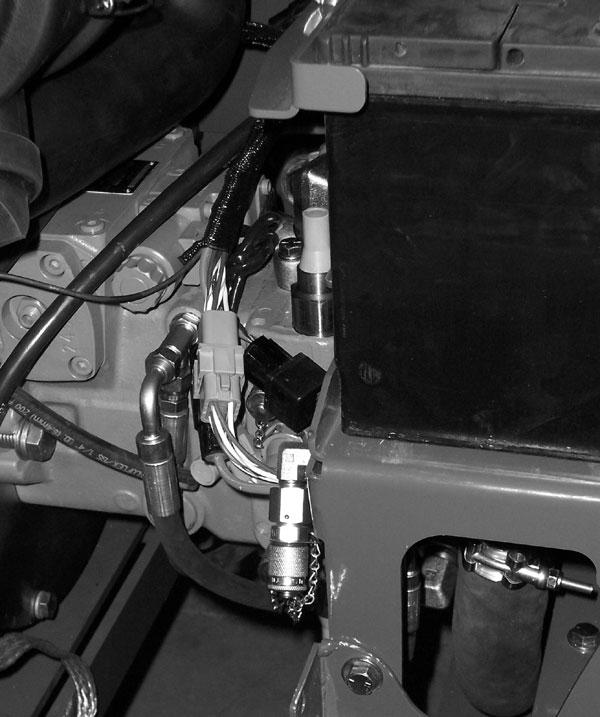
Hydraulic Pressure Test Port: Located off the rear of the battery tray; a gauge can be attached to this port to check main valve and steering pressures.
Right Side RearView Mirror: Located on the right side of the machine; it provides the operator a view of the area on the right side and behind the machine.
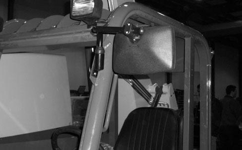
Left Side RearView Mirror(optional): Located on the left side of the cab; it provides the operator a view of the area on the left side and behind the machine.
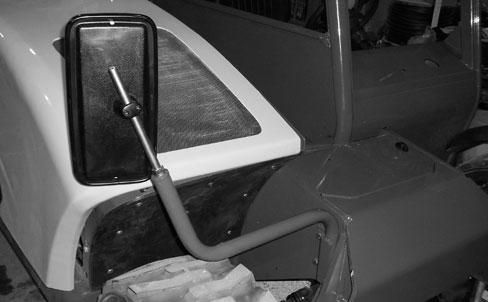
Cab Right Side Window orPanel: Located on the right side of the cab; this window or panel protects the operator from coming in contact with the boom.
Cab RearWindow: Located on the rear of the cab; this window protects the operator from material flying off the rear wheel.
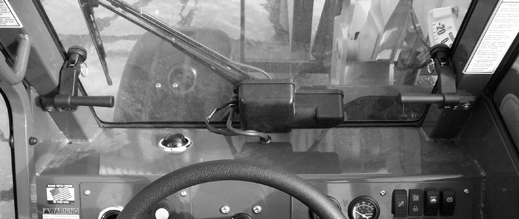
Front Window Emergency Exit: When equipped with the optional fully enclosed cab, the front window serves as an emergency exit. Pull the pin on each window hold-open, then push the window open and exit.
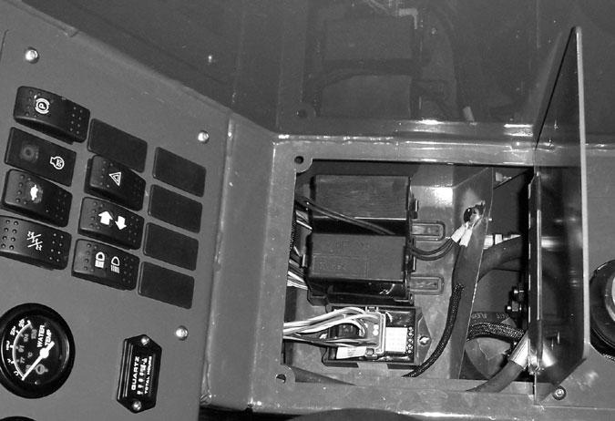
Fuse and Relay Functions: Refer to the illustration and following description for the fuse and relay functions.
Fuse and Relay Compartment: Located under the hinged load chart panel; lift the front of the panel to access the fuses and relays.
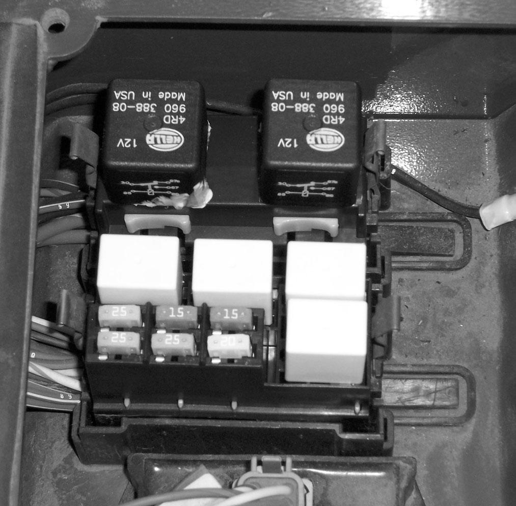
FUSES:
1.15 AMPFuse: ignition switch, horn, brake lights, glow plug
2.20 AMPFuse: transmission, neutral start, park brake, steer mode, injector pump, backup alarm
3.15 AMPFuse: lights, turn signals, hi/low speed
4.25 AMPFuse: gauges, heater
5.25 AMPFuse: top wiper motor
6.25 AMPFuse: front wiper motor
RELAYS:
A.40 AMPChange-over Relay: park brake
B.40 AMPChange-over Relay: ignition
C.20 AMPRelay: top wiper
D.20 AMPRelay: lights
E.20 AMPRelay: bulb check
F.20 AMPRelay: front wiper
Attachment Tools
Mustang offers a versatile range of attachment tools to meet various lifting and material handling applications. Contact your Mustang dealer for specifications and ordering information.
Accessories
Mustang offers a range of special accessories for this machine. Contact your Mustang dealer for specifications and ordering information.
NOTE: All accessories are field-installed unless otherwise noted. Information and parts for installing accessories are provided by the Mustang Manufacturing Company or Mustang Telehandler dealers.
Chapter 6 OPERATION AND ADJUSTMENTS
Generalinformation
Caution
BEFORE starting the engine and operating the Telehandler, review and comply with ALLsafety recommendations in the Safety chapter of this manual. Know how to STOPthe machine before starting it. Also, BE SURE to fasten and properly adjust the seatbelt.
ENGINE BREAK-IN
Anew engine does not require extensive “break-in.” However, for the first 100 hours of operation, follow these guidelines: Allow the engine to idle for a few minutes after every cold start. DO NOTidle the engine for long periods of time. DO NOToperate the engine at maximum power for long periods of time. Check the oil level frequently and replenish as necessary with the oil specified in the engine manual.
Deutz engines do not use a “break-in” oil. After the first 100 hours of operation, change the oil and replace the oil filter. Consult the Lubrication chapter for the type and grade of oil to use. Refer to the Service and Storage chapter for the proper service intervals.
PRE-START INSPECTION
It is the operator’s responsibility to inspect the machine before the start of each workday. Every pre-start inspection must include more than checking the fuel and oil levels. It is a good practice to personally inspect any machine you are assigned to use, even though it has already been put into service by other personnel.
The most efficient method of checking a machine is by conducting a “Walk-Around Inspection.”
Before mounting the operator’s compartment, walk completely around the machine to be sure no one is under, on, or close to it. Let others in the area know you are going to start up and wait until everyone is clear of the machine.
Before Starting Engine
Before starting the engine and running the machine, refer to the Indicators and Controls chapter and become familiar with the various operating controls, indicators and safety features.
Starting The Engine
Warning
ALWAYS fasten your seat belt before starting the engine. Leave the parking brake applied until the engine is running and you are ready to operate the machine.
The following procedure is recommended for starting the engine:
1.Grasp the hand holds to step up into the operator’s compartment.
2.Adjust the seat and fasten the seatbelt.
3.Check that all controls are in their “neutral” positions, except the parking brake switch, which should be in the “ON” position.
4.Turn the key switch to “ON” position and press the start button. If the button is released before the engine starts, turn the keyswitch to “OFF” position and allow the starter to stop before attempting to start again.
IMPORTANT: Crank the starter until the engine starts. If the engine fails to start within 20 seconds, return the key to the “OFF” position, wait 2 minutes, and try again to start the engine. Cranking the engine for longer than 20 seconds will result in premature failure of the starter.
5.After the engine starts, allow a sufficient warm-up time before operating the controls.
6.Check that indicators are in normal condition.
7.Check that there are no fuel, oil or engine coolant leaks, and no abnormal noises or vibrations.
Cold Starting
Ablock heater is recommended for starting in temperatures of 20°F (-7°C) or lower.
If the battery becomes discharged and does not have sufficient power to start the engine, jumper cables can be used for starting assistance. Refer to the jump starting instructions in the Service and Storage chapter of this manual for safe jump starting procedures.
Cold Starting Procedures
Warning
Do not use starting fluid (ether) with engine preheat systems. An explosion can result, which can cause engine damage, injury or death.
If prevailing temperature is 32°F (0°C) or below, it may be necessary to use a cold weather starting aid to start the diesel engine.
1.Turn the key switch completely to the right against the spring load to activate the engine preheat. The engine preheat indicator lamp located in the switch panel will light.
2.Hold the key in this position for approximately one minute.
3.While holding the key in the preheat position, press the start button to start the engine.
4.Release the key and start button when the engine starts.
Stopping
The following procedure is the recommended sequence for stopping the machine:
1.Bring the machine to a stop on a level surface. Avoid parking on a slope, but if necessary, park across the slope and block the tires.
2.Fully retract the boom and lower the attachment to the ground. Idle the engine for gradual cooling.
3.Place controls in neutral. Apply the parking brake.
4.Turn the ignition switch key to the “OFF” position. Remove the key.
5.Unfasten the seatbelt, and grasp the hand holds while climbing out of the operator’s compartment.
First Time Operation
Caution
Be sure the area used for test-running is clear of spectators and obstructions. Initially, operate the machine with an empty attachment tool.
Make sure the engine is warm and then go through the following procedures:
Select the travel direction. Switch off the parking brake and move ahead slowly, while testing the steering and brakes. Stop and operate all boom and attachment tool function controls, checking for smooth response.
Apply the service brakes, stop the machine and move the travel lever to the opposite direction.
IMPORTANT: To prevent damage to the transmission, the Telehandler should be traveling at a slow speed and not accelerating when changing the direction of travel.
Parking Brake
NOTE: The parking brake mechanism within the front axle is NOT designed for, OR intended to be used as, the primary means of stopping movement of the machine. Hydraulic braking provided through the service brakes within the axles is the primary means for stopping movement. The axleby-axle split brake system is the secondary means of stopping movement.
The proper sequence for correct machine operation is to always engage the parking brake switch before shutting off the engine; and to disengage the parking brake ONLYafter the engine is running. In an EMERGENCY, if it becomes necessary to stop the machine, activate the parking brake switch to “ON.”
Changing Attachment Tools
The Telehandler boom nose will accept Mustang Quick-attach System attachment tools. The Quickattach System has a quick-release hookup and locking mechanism for mounting framing-type or masonrytype attachment tools to the boom nose.
Attaching
To pick up the attachment tool, proceed as follows: plate up and outward at least 180o so it is in position to re-lock on the next attachment tool.
1.Raise the boom slightly, extend it 2 to 3 feet (600900 mm) for better visibility, and tilt the Quickattach System forward.
2.Align the Quick-attach System squarely with the back of the attachment tool.
3.Slowly extend the Quick-attach System and lower the hooks under the attachment tool hookup bar.
4.Tilt the Quick-attach System back so that the lock plate engages the attachment tool. This secures the attachment tool to the Quick-attach System.
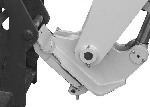
5.For an attachment tool with auxiliary hydraulics, connect hoses to the quick-disconnect connectors on the boom nose.
4.Tilt the Quick-attach System forward to allow the attachment tool to roll out, then lower the boom so the hook ears clear the hookup bar on the attachment tool.
NOTE: One side of the lock plate has a bright red decal to indicate the unlocked position.
5.If the attachment tool has auxiliary hydraulics, disconnect the hoses from the quick-disconnects on the boom nose.
6.Start the engine and tilt the Quick-attach System forward, then slowly back the machine until the attachment tool is free from the boom nose.
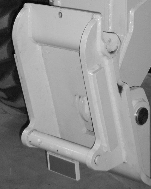
Quick-attach System Attaching Detail
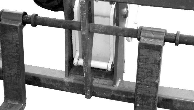
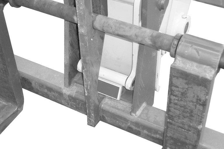
Detaching
To detach attachment tool, proceed as follows:
1.Raise the boom slightly and extend it 2 to 3 feet (600-900 mm) for better visibility. Lower the boom until the attachment tool is approximately 12” (300 mm) off the ground.
2.Roll the carrier rearward as far as it will go. When the carrier is rolled all the way back, perform the Mandatory Safety Shutdown Procedure (p. 8, Safety chapter).
3.With the engine off, leave the operator’s station. Manually raise the lock spring, and flip the lock
Quick-attach System Detaching Detail
Warning
Modifications, alterations to, or use of attachment tools not authorized by Mustang (or the manufacturer) in writing can void warranty and cause machine damage and/or serious personal injury or death.
SELF-LEVELING
The machine is equipped with a hydraulic self-leveling feature. This feature is designed to keep the attachment tool level while the boom is being raised.
Generalmachine Operation
Check the Telehandler to be sure all systems are in good operating condition. Perform the following steps before starting the machine the first time each day:
1.Check the engine oil, coolant and hydraulic oil levels.
2.Check hydraulic oil cooler and engine radiator for debris.
3.Be sure weekly lubrication has been done.
4.Visually inspect for leaks and broken or malfunctioning parts. Be sure all caps, covers and safety shields are in place.
5.Check tires for cuts, bulges, nails, correct pressure, loose wheel nuts, etc.
6.Inspect the work area. Be sure you know where you will make load pickups, lifts and turns. Look over the terrain of the jobsite for holes, obstacles, slippery surfaces, and soft or deep mud.
7.Check clearances of ramps, doorways and passage-ways. Check overhead clearances if you will travel and place loads near power or telephone lines.
Warning
Exhaust fumes can kill. Ensure proper ventilation when starting indoors or in enclosed areas.
Use proper hand holds, NOT the steering wheel or control levers when mounting and dismounting.
NEVER operate the machine with safety guards or covers removed.
Over-inflated tires can explode and cause injury or death. Tire repairs MUST be made only by authorized personnel using proper tools and equipment.
If the machine is in need of repair or in any way unsafe, or contributes to an unsafe condition, the matter must be reported immediately to the user’s designated authority. The machine must NOTbe operated until it has been restored to a safe operating condition.
Operate the travel controls gradually and smoothly when starting, stopping, turning and reversing direction.
Grade and Slope Precautions
The Telehandler complies with industry stability test requirements and is stable when properly operated.
However, improper operation, faulty maintenance, and poor housekeeping can contribute to a condition of instability and defeat the purpose of the standard.
The amount of forward and rearward tilt to be used is governed by the application. Although use of maximum rearward tilt is allowable under certain conditions, such as traveling with the load fully lowered, the stability limits of the machine, as determined by the industry standard tests, do not encompass consideration for excessive tilt at high elevations, or the handling of off-center loads.
Only handle loads within the capacity limits of the machine, and which are stable and safely arranged. When attachments are used, extra care should be taken in securing, manipulating, positioning and transporting the load.
Grade Limits
NOTE: Grade limits are based on ANSI/ITSDF standard B56.6-2005.
This Telehandler meets or exceeds the safety standard (ANSI/ITSDF B56.6) stability limits for rough terrain forklifts. The stability tipping limits cover specific, controlled test conditions, which are extremes, and which are not intended to be achieved during normal worksite operations. The following specifications are provided only as information to the operator, and must not be used as a guideline for operating the Telehandler. For safe operation, always follow the instructions and warnings provided in this manual.
1.DO NOTplace or retrieve loads on an up or down slope or grade that exceeds 7% or 4°.
2.DO NOTtravel up or down a grade or slope that exceeds 22% or 12° while loaded.
3.DO NOTplace or retrieve loads on a side hill with a slope or grade that exceeds 12% or 7°. Check the location of the ball in the frame angle indicator located on the ROPS/FOPS cross member. If the ball in the frame angle indicator is in the green zone, it is safe to place or retrieve the load. If the ball in the frame angle indicator is in the yellow zone, use slower movements and extra caution to ensure remaining within the limits of the load chart, because the machine is nearing an unstable condition. If the ball in the frame angle indicator is in the red zone, loads cannot be placed or retrieved.
4.DO NOTtravel across a side hill that exceeds 18% or 10° grade. Check the frame angle indicator on the ROPS/FOPS cross member to determine the angle of the grade. The attachment tool MUSTbe maintained at the “carry” position, with the boom fully retracted and attachment tool at minimum ground clearance.
When ascending or descending grades in excess of 5% or 3°, the machine should be driven with the load upgrade. An unloaded machine should be operated on all grades with the load handling attachment tool downgrade, tilted back if applicable, and raised only as far as necessary to clear the ground surface.
Avoid turning if possible and use extreme caution on grades, ramps and inclines. Normally travel straight up and down the slope.
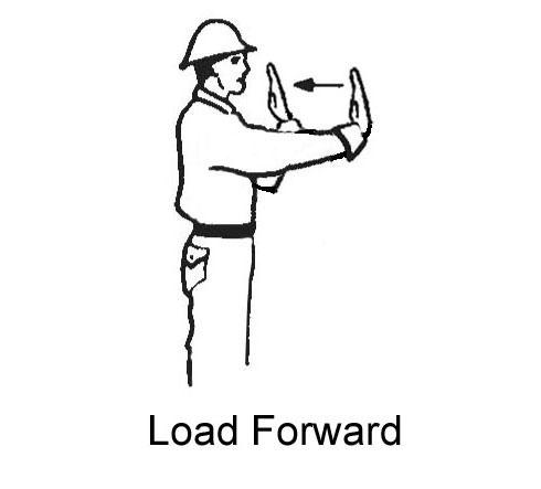
Traffic Flow Patterns
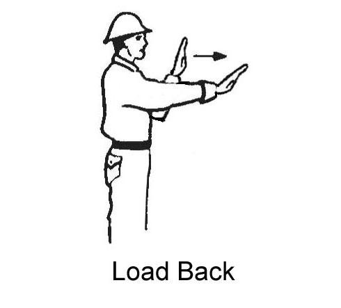
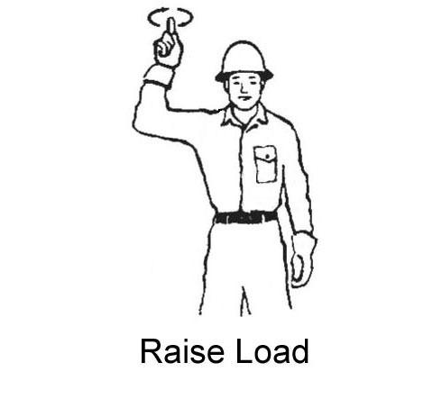
Know and understand the traffic flow patterns of your jobsite. Know all Telehandler hand signals for safety. Use signal persons as necessary for safe operation, and be sure you can see the signal person and acknowledge the signals given.

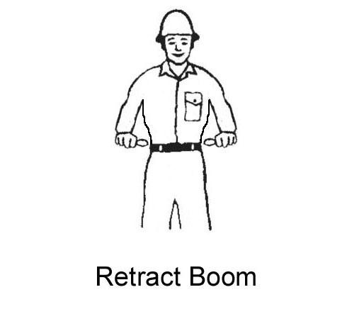


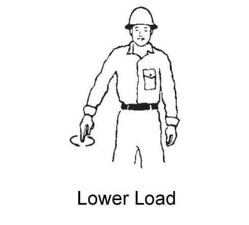
Safety Hand Signals

When ramps must be used in transporting loads with the machine, the following are the minimum widths for safe travel:
Compacted dirt, gravel, etc.12 ft. (3.6 m)
Woodboard, concrete, etc.10 ft. (3.0 m)
Permanent aisles, roadways and passageways, floors and ramps must be clearly defined or marked. Permanent or temporary protrusion of loads, equipment, material and construction facilities into the usual operating area must be guarded, clearly and distinctively marked, or clearly visible.
Maintain a safe distance from the edge of ramps, platforms and other similar working surfaces.
Controlled lighting of adequate intensity should be provided in operating areas. Where operating conditions indicate, the operator/user is responsible for having the machine equipped with lights.
Provisions must be made to prevent trucks, semi-trailers and railroad cars from being moved during loading and unloading.
Wheel stops, parking brakes, or other positive holding means must be used to prevent movement during loading and unloading.
DO NOTmove railroad cars and trailers with the Telehandler.
DO NOTuse the boom and attachment for leverage to push the machine out of mud.
IMPORTANT: DO NOT lower boom at high engine speed when attachment tool is at maximum rearward tilt, because damage to slave cylinders may result.
Generalload Handling
NEVER attempt to work controls except from the operator’s seat. NEVER jerk or use fast movements. Avoid sudden stops, starts and changes in direction.
Operation of the hydraulic system depends on engine speed and the distance the controls are moved. When operating these controls it is important to develop a technique called “feathering.” Feathering the control means starting the desired motion by moving the control a small amount away from neutral. Then after movement has started, the control can be eased to full movement. Use the same feathering technique to stop the motion.
Warning
Excessive speed can be hazardous. ALWAYS exercise caution and good judgement while operating the machine.
ALWAYS maintain a safe distance from electric power lines and avoid contact with any electrically charged conductor and gas line. It is not necessary to make direct contact with a power line for power to ground through the structure of the machine. Keep the boom and load at least 10 ft. (3 m) from all power lines. Accidental contact or rupture can result in electrocution or an explosion. Contact the North American One-Call Referral System at (888) 258-0808 for the local “Digger’s Hotline” number or proper local authorities for utility line locations BEFORE starting to dig!
Keep all body parts inside the operator’s station while operating the machine. BE SURE of clearance for the attachment tool when turning, working around buildings, etc.
Turning corners too fast can tip the machine, or cause a load to tip off the attachment. Sudden slowing or stopping of the machine may cause the load to drop off the attachment tool.
Be certain you can control both speed and direction before moving. Always place the machine in neutral and set the parking brake before raising or extending the boom. NEVER drive the machine up to someone standing in front of the load.
NEVER leave the operator’s station without first lowering the attachment tool to the ground. Then set the parking brake, place controls in neutral, shut off engine and remove the key. AVOID parking the machine on a slope, but if necessary, park across the slope and block the tires.
Load Capacity and Reach
This machine has flip-charts in the operator’s station that provide the load capacity limits at various positions of attachment tool extension and elevation. Aset of the load zone charts is reproduced at the end of this manual for reference.
Atypical load zone chart is shown on the next page. The scale on the left indicates height in feet above the ground level. The scale on the bottom shows the distance in feet out from the front of the machine. The arc lines noted by the numbers “1” through “4” correspond to the position extension markers on the operator side of the inner boom section.
The following example illustrates proper use of the load zone charts for the Telehandler:
Example:
The operator, using a standard carriage attachment tool, wants to raise a 4000 pound load 10 feet high, and can only get to within 5 feet of the load placement point. Can it be done within the capacity of the machine?
Analysis: See “Typical Load Zone Chart” below.
Projecting up from the 5-foot mark on the horizontal axis to intersect a line through the 10-foot mark on the vertical axis shows the load can be placed in the 4000 pound zone.
During placement, the operator observes when the extension reference number “2” on the boom becomes visible and stops. The maximum safe distance of extension with this load has been reached.
Warning
NEVER exceed the rated operating capacity of the Telehandler as shown on the load zone charts.
Lifting Attachment Tool Applications
Picking Up the Load
Inspect the load. If it appears unstable, DO NOT attempt to move it. DO NOTattempt lifting doubletiered loads, or straddling side-by-side pallets with one on each fork. NEVER add extra unauthorized counterweights to this machine.
Warning
Operating conditions can reduce the machine’s safe operating capacity. Exceeding the capacity when raising or extending the boom will cause the machine to tip forward.
Approach the load squarely and slowly with the machine straight and level. Adjust the space between forks, if necessary. Engage the load equally on both forks until the load touches the carriage backrest. Tilt the forks back to position the load for travel.
Carrying the Load
If the load obstructs your view, get someone to direct you. Maintain ground speeds consistent with ground conditions and which permit stopping in a safe manner.
Warning
NEVER travel with the boom above the carry position (attachment tool should be at minimum ground clearance). Boom should be fully retracted.
NEVER coast with the transmission in neutral. Travel up and down grades slowly.
DO NOT operate the machine on a slope or grade that exceeds 22% or 12o.
Elevating and Placing the Load
For ground level placement, be sure the area under the load and around the machine is clear of equipment and personnel. Lower the load to the ground, tilt the forks to the horizontal position, and then back away carefully to disengage the forks from the load.
Warning
DO NOT raise the boom until you check the frame angle indicator to verify that the ball is in a safe zone for raising and placing a high load.
For elevated or overhead placement, bring the machine as close as possible to the landing point. Use extreme caution for high placement. Be sure personnel are clear of the area.
Warning
Be sure that the surrounding ground has adequate strength to support the weight of the machine and the load it is carrying.
Always wear the seat belt provided to prevent being thrown from the machine. If you are in an overturn:
- DO NOT jump!
- Hold on tight and stay with the machine!
- Lean away from the fall!
Set the parking brake, hold the service brake pedal fully applied and slowly raise the load, maintaining a slight rearward tilt to cradle the load. As the load approaches the desired height, feather the boom control at minimum speed until the load is slightly higher than the landing point.
Continue the feathering technique and lower the load into place. Free the forks from the load by alternately retracting and raising the boom. If this process is not possible, very slowly and carefully reverse the telehandler to free the forks from the load. Lower the forks to travel height.
Warning
The machine becomes less stable as the load is raised higher. As lift height increases, the operator’s depth perception decreases. High elevation placements may require a signal person to guide the operator.
DO NOT ram the lift cylinders to the end of the stroke. The resulting jolt could spill the load.
The truss boom attachment tool should ONLY be used to lift and place loads when the machine is in a stationary position. DO NOT use to transport loads around the jobsite. This can cause the load to swing, resulting in either the load dropping or the machine tipping over.
If a hydraulic boom circuit hose bursts with the boom up, shut down the machine and call your Mustang dealer. DO NOT attempt to lower the boom or make repairs.
Suspended Loads
The handling of suspended loads by means of the truss boom or other similar device can introduce dynamic forces affecting the stability of the machine that are not considered in the stability criteria of industry test standards. Grades, sudden starts, stops and turns can cause the load to swing and create a hazard.
DO NOTexceed the Telehandler capacity for handling suspended loads. Only lift the load vertically; NEVER drag it horizontally. Use tag lines to restrain load swing whenever possible.
Guidelines for “Free Rigging / Suspended Loads”
1.The rigging equipment must be in good condition and comply with the applicable U.S. OSHAregulation, 1910.184, “Slings,” or 1926.251, “Rigging equipment for material handling.”
2.The rigging equipment must be secured to the forks such that it cannot slip or slide either sideways or fore and aft.
3.The capacity of the fork(s) and the machine (whichever is less) must not be exceeded.
4.The load center must remain at 24” (610 mm) or less.
5.No lifting of material may be done when anyone is on the load, rigging or forks.
6.Multiple pickup points on the load are preferred to prevent the load from rotating, but a single pickup point may be used if one or more tag lines are utilized. And, of course, the load must never be positioned over personnel at any time.
Road Travel
For short distance highway travel, attach a SlowMoving Vehicle (SMV) emblem (purchased locally) to the rear of the Telehandler. For highway operation, obtain and install an amber flashing beacon.
NOTE: ALWAYS follow ALLstate and local regulations regarding the operation of equipment on or across public highways. Whenever there is an appreciable distance between jobsites, or if driving on public highway is prohibited, transport the machine using a vehicle of appropriate size and capacity.
Transporting Between Jobsites
ALWAYS abide by the following recommended procedures and guidelines when using ramps to load the machine onto (and unload it from) a truck or trailer. Failure to heed can result in damage to equipment and serious personal injury or death!
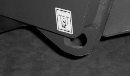
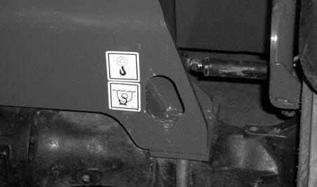
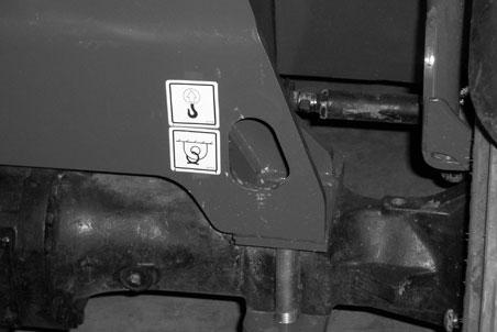
Tie-down points are provided for inserting chains to secure the machine during transport.
1.The ramps MUSTbe of sufficient strength to support the machine. Whenever possible, the use of strong steel ramps is recommended as well as center supporting blocks.
2.The ramps MUSTbe firmly attached to the truck or trailer bed with NO step between the bed and the ramps.
3.Incline of ramps MUSTbe less than 15 degrees. Ramp length MUSTbe at least 16 feet (4.9 m) long.
4.Ramp width MUSTbe at least 1-1/2 times the tire width.
5.Block the front and rear of the tires on the truck or trailer; engage the parking brake.
6.Position the machine with the boom facing toward the front of the truck or trailer so that it is straight in line with the ramps. Slowly (at the lowest engine speed possible) and carefully drive the machine up the ramps.
7.Tie-down points are provided at the front and rear corners of the frame structure.
Warning
NEVER adjust travel direction (even slightly) while on the ramps. Instead, back off the ramps, and then realign the machine with the ramps.
Warning
Loading Machine Using Ramps
NOTE: Amatched pair of ramps is required.
NEVER transport the machine with the boom raised or extended. BE SURE to secure the machine (including boom) to the truck or trailer bed using chain and binders or steel cables, to prevent any movement while transporting.
Unloading Machine Using Ramps
NOTE: Amatched pair of ramps is required. Repeat Steps 1 through 5 and proceed as follows to unload the machine:
6.Remove the tie-down chains/cables.
7.If necessary, adjust the machine so that the wheels are in line and centered with the ramps.
8.Slowly (at the lowest engine speed possible) and carefully drive the machine down the ramps.
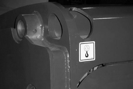
The Telehandler can be lifted using the four lifting points shown above.
Lift equipment used and its installation is the responsibility of the party conducting the lift. All rigging must comply with applicable regulations and guidelines.
Warning
Before lifting, check the lifting equipment for proper installation.
-Never allow riders in the operator’s station while the telehandler is lifted.
-Keep everyone a safe distance away from the telehandler while it is lifted.
-The telehandler may only be lifted without a load on the forks, or without an attachment. Never lift the telehandler with attachment other than those stated.
1.Using suitable lift equipment, hook into the lift eyes. Adjust the length of the slings or chains to lift the telehandler level.
IMPORTANT: As needed, use a spreader bar to prevent the slings or chains from rubbing the sides of the boom.
2.Center the hoist over the Telehandler. To prevent shock loading of the equipment and excessive swinging of the load, slowly lift the Telehandler off the ground. Perform all movements slowly and gradually. As needed, use a tag line to help position the Telehandler.
Towing The Telehandler
If the machine becomes disabled, it can be towed for a short distance. To tow the Telehandler, the high pressure limiters on the hydrostatic transmission must be unlocked and the SAHR parking brake must be released.
Warning
Do not tow the Telehandler at more than 3 mph (5 km/h), and only for short distances (less than 100 yards).
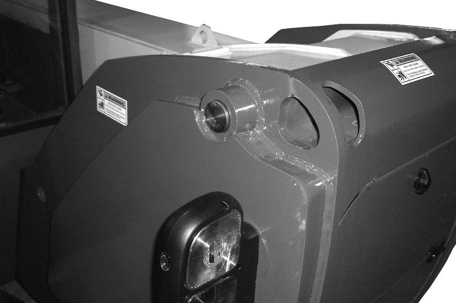
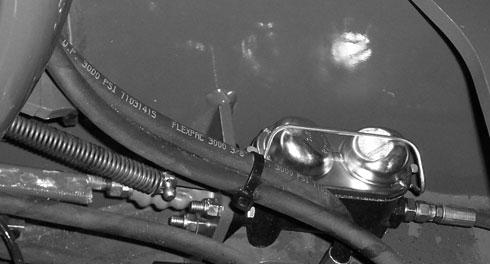
Hydrostatic Transmission Unlocking Procedure
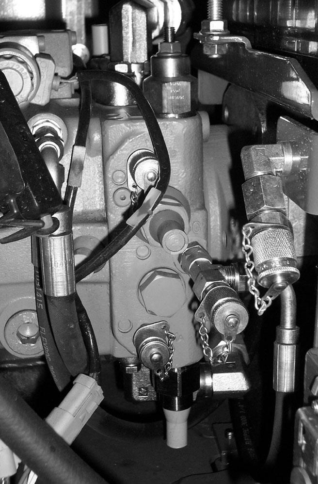
1.Remove the plastic caps on the high pressure limiters.
Upper High Pressure Limiter with Cap Removed
Lower High Pressure Limiter with Cap Installed
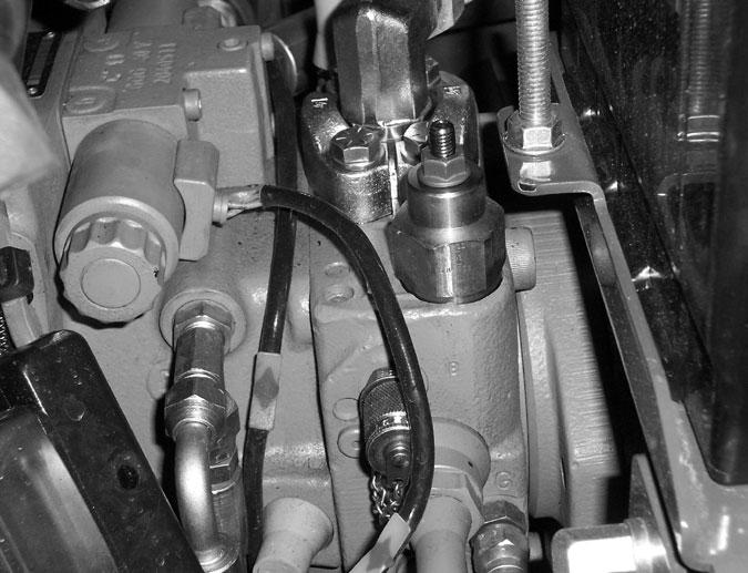
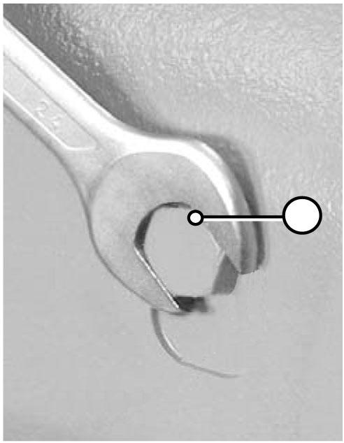
2.Loosen the jam nut on a high pressure limiter.
3.While holding the jam nut, use an Allen wrench to turn the center release screw in until it bottoms.
4.Tighten the jam nut.
5.Repeat steps 2-4 for the other high pressure limiter.
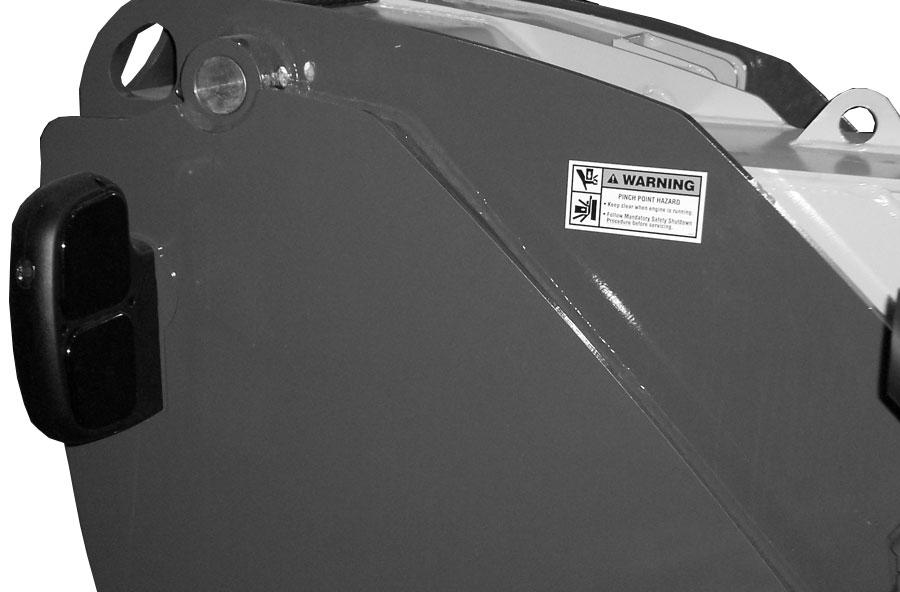
SAHR Parking Brake Releasing Procedure
1.There are unlocking screws on the front and rear sides of the axle. Locate and loosen both unlocking screws (1) and remove the stop washers (3).
SAHR Parking Brake Applying Procedure
1.Loosen the unlocking screws (1) and re-install the stop washers (3).
2.Tighten the unlocking screws against the stop washers.
Hydrostatic Transmission Locking Procedure
1.Loosen the jam nut on a high pressure limiter.
2.Using an Allen wrench, turn the center release screw back out until it stops.

3.Tighten the jam nut.
4.Repeat steps 1-3 for the other high pressure limiter.
Theft Deterrents
Mustang has recorded all major component part numbers and serial numbers. Users should take as many of the following actions as possible to discourage theft, to aid in the recovery in the event the machine is stolen, and to reduce vandalism:
1.Remove keys from unattended machines.
2.Attach, secure, and lock all anti-vandalism and anti-theft devices on the machine.
3.Lock doors of cabs when not in use.
4.Inspect the gates and fences of the equipment storage yard. If possible, keep machines in well-lighted areas. Ask the local law enforcement agency to make frequent checks around the storage and work sites, especially at night, during weekends, and on holidays.
Warning
Before the Telehandler can be returned to service, the SAHR parking brake must be returned to the applied position, and the hydrostatic transmission high pressure limiters must be locked.
5.Report any theft to your dealer and insurance company. Provide the model and all serial numbers. Request your dealer to forward this information to Mustang Manufacturing Company.