5 minute read
Upper main line installation

from CNH Multi-purpose circuit proportional control kit - CX210D Crawler excavator Manual 47844483 - PDF
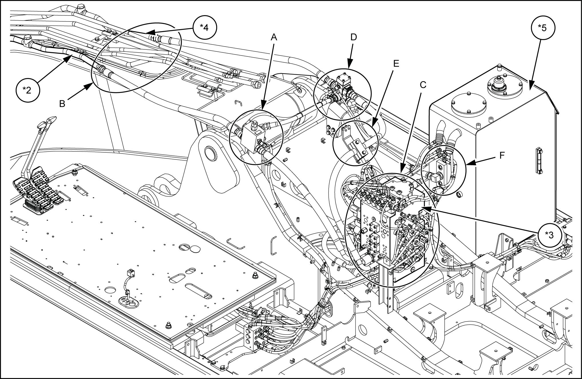
Upper main line installation (left side)
Install the bracket the frame with four sems bolts (12)
Install the shut - f valve (10) the bracket with two sems bolts (12)
• Adjust the set pressure for the relief valve (*1) the shut - f valve (10) match the type attachment
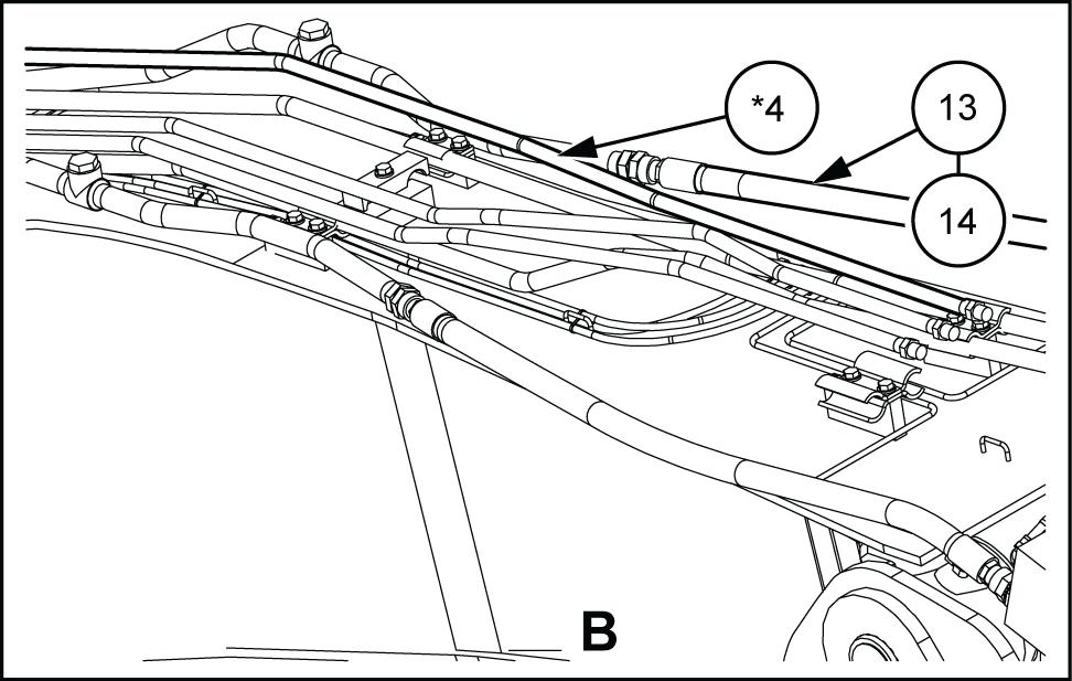
Install the hose adapter (8) the shutof f valve (10) B Set the O - ring (13) the hose adapter (8) and connect the hydraulic hose (14)
• Hydraulic hose tightening torque: 184 - 226 N·m ( 136 - 167 )
Set the O - ring (13) the line assembly (left) (*2) and connect the hydraulic hose (14)
• Hydraulic hose tightening torque: 184 - 226 ( 136 - 167 )
SMIL15CEX2556AB 3
Install the hose adapter (8) the shutof f valve (10) A
Set the O - ring (13) the hose adapter (8) and connect the hydraulic hose (20)
• Hydraulic hose tightening torque: 184 - 226 N·m ( 136 - 167 ) .
SMIL15CEX2845AB 4
Set the O - ring (5) the control valve (*4) and install the hydraulic hose (20) with two split flanges (6) and four hexagon socket head bolts (7)


SMIL15CEX2846AB 5
Upper main line installation (right side)
Install the bracket (18) the frame with four sems bolts (19)
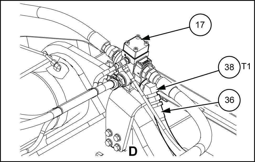
Install the three - direction valve (17) the bracket (18) with two sems bolts (19)
Install the hose adapter (15) the three - direction valve (17) A
Set the O - ring (13) the hose adapter (15) and nect the hydraulic hose (14)
• Hydraulic hose tightening torque: 184 - 226 N·m ( 136 - 167 )
SMIL15CEX2560AB 7
Set the O - ring (13) the line assembly (right) (*4) and connect the hydraulic hose (14)
• Hydraulic hose tightening torque: 184 - 226 ( 136 - 167 )
SMIL15CEX2561AB 8
Install the elbow (38) the three - direction valve (17)
Connect the hydraulic hose (36) the elbow (38)
SMIL15CEX2562AB 9
Install the elbow (37) the hydraulic tank (*5) Connect the hydraulic hose (36) the elbow (37)

SMIL15CEX2563AB

Install the hose adapter (15) the three - direction valve (17) B
Set the O - ring (13) the hose adapter (15) and connect the hydraulic hose (4) .
• Hydraulic hose tightening torque: 184 - 226 N·m ( 136 - 167 )
Install the bracket (24) the housing frame (*6) with two sems bolts (27)
Sandwich the hydraulic hose (4) with two hose clamps (26) , and then install the plate (25) with two sems bolts (27) order fasten the
SMIL15CEX2848AB
Set the O - ring (21) the control valve (*3) and install the hydraulic hose (4) with two split flanges (22) and four hexagon socket head bolts (23)


Install the check valve (33) the control valve (*3)
Set the O - ring (30) the check valve (33) and connect the hydraulic hose (31) .
Install the stud (28) the control valve (*3) and then install the elbow (29) Set the O - ring (30) the elbow (29) and connect the hydraulic hose (31)

• Hydraulic hose tightening torque: 157 - 193 ( 1 - 142 )
Install the hose adapter (35) the shutof f valve (10) T
Install the hose adapter (35) the three - direction valve (17) port.
Connect the shut - f valve (10) T port and threetion valve (17) port with the hydraulic hose (34)

Pilot line installation - proportional control


Hose assembly *2. Manifold


Code *3. Control valve *1. Floor *4. Hydraulic tank
Install the reducing valve (43) the bracket (45) with two sems bolts (44)
Install the bracket (45) the floor (*1) with two sems bolts (46)
Install the solenoid valve (53) the bracket (52) with two spring washers (56) and two high - strength bolts (55)


Install the bracket (52) the floor (*1) with two sems bolts (54)
Install the hose adapter (47) the reducing valve (43) T
SMIL15CEX0823BB 5
• T ightening torque: 25.431.4 N·m ( 18.723.2 ) SMIL15CEX3051AB 6
Install the tee (57) the solenoid valve (53) T Connect the reducing valve (43) T port and solenoid valve (53) T port with the assembly hose (50)

Install the nipple with filter (49) the reducing valve (43) P
• T ightening torque: 25.431.4 ( 18.723.2 )
Install the tee (57) the solenoid valve (53) P port.
Connect the reducing valve (43) P port and solenoid valve (53) P port with the assembly hose (50)
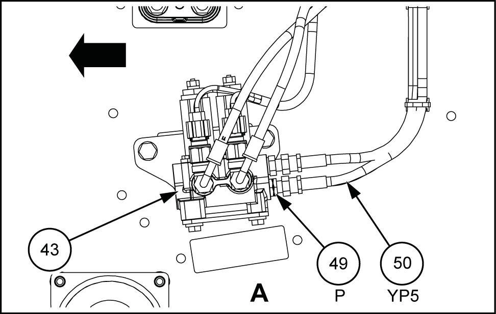
Fasten the assembly hoses (50) (YT5) and (YP5) with the special band (51)

Install the tee (48) the reducing valve (43) port.
• T ightening torque: 25.431.4 N·m ( 18.723.2 )
SMIL15CEX0838BB
Install the elbow (60) the control valve (*3) pb2
Connect the reducing valve (43) port and control valve (*3) pb2 port with the assembly hose (50)


Install the tee (48) the reducing valve (43) port.
• T ightening torque: 25.431.4 N·m ( 18.723.2 )
SMIL15CEX0838BB
Install the elbow (60) the control valve (*3) pa2
Connect the reducing valve (43) port and control valve (*3) pa2 port with the assembly hose (50) SMIL15CEX0843AB
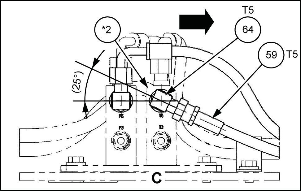
1 Install the elbow (64) the manifold (*2)
Connect the solenoid valve (53) T port and manifold (*2) port with the assembly hose (59) SMIL15CEX0844AB

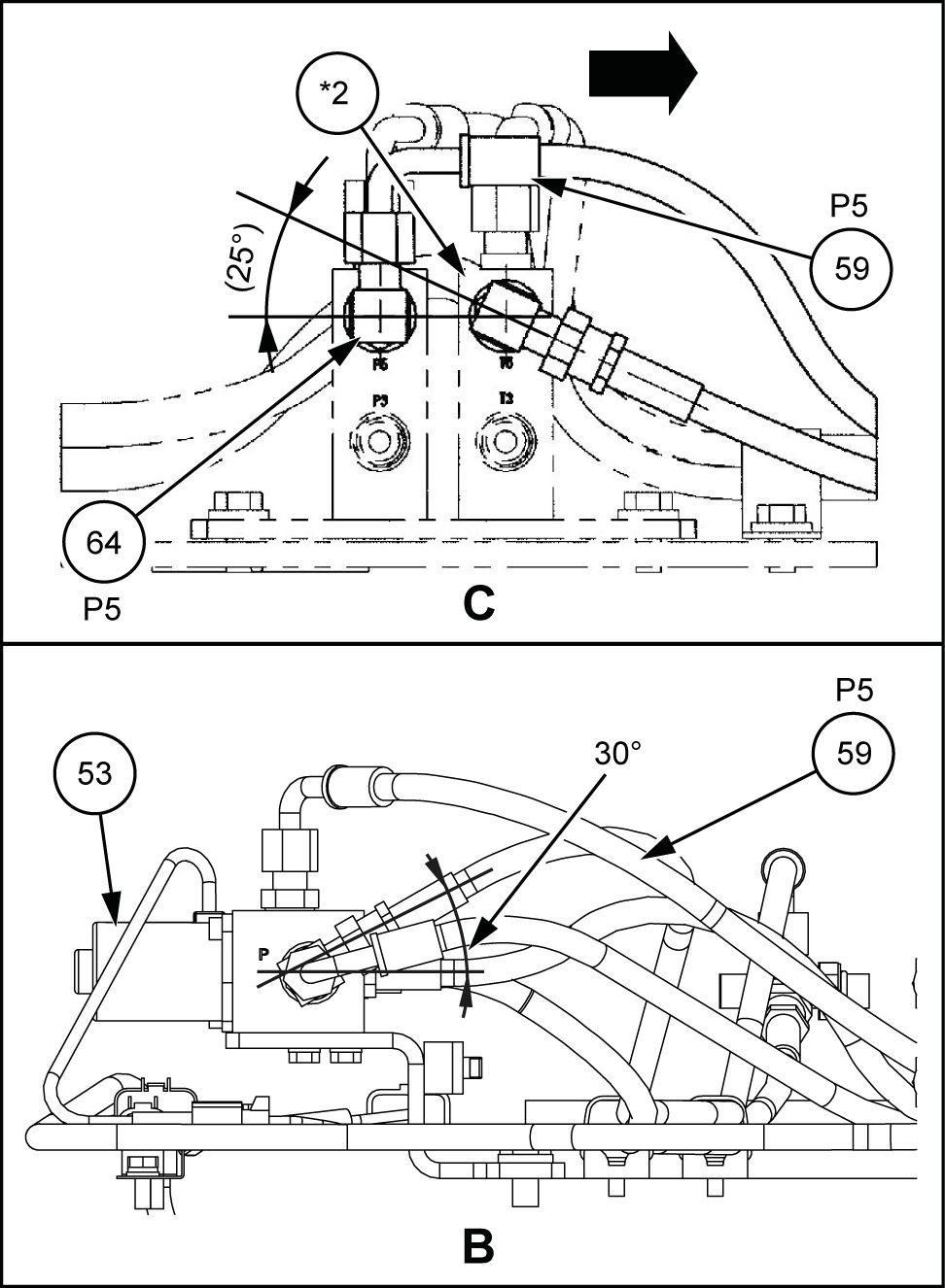
12. Install the elbow (64) the manifold (*2) port.
Connect the solenoid valve (53) P port and manifold (*2) port with the assembly hose (59) SMIL15CEX0845BB
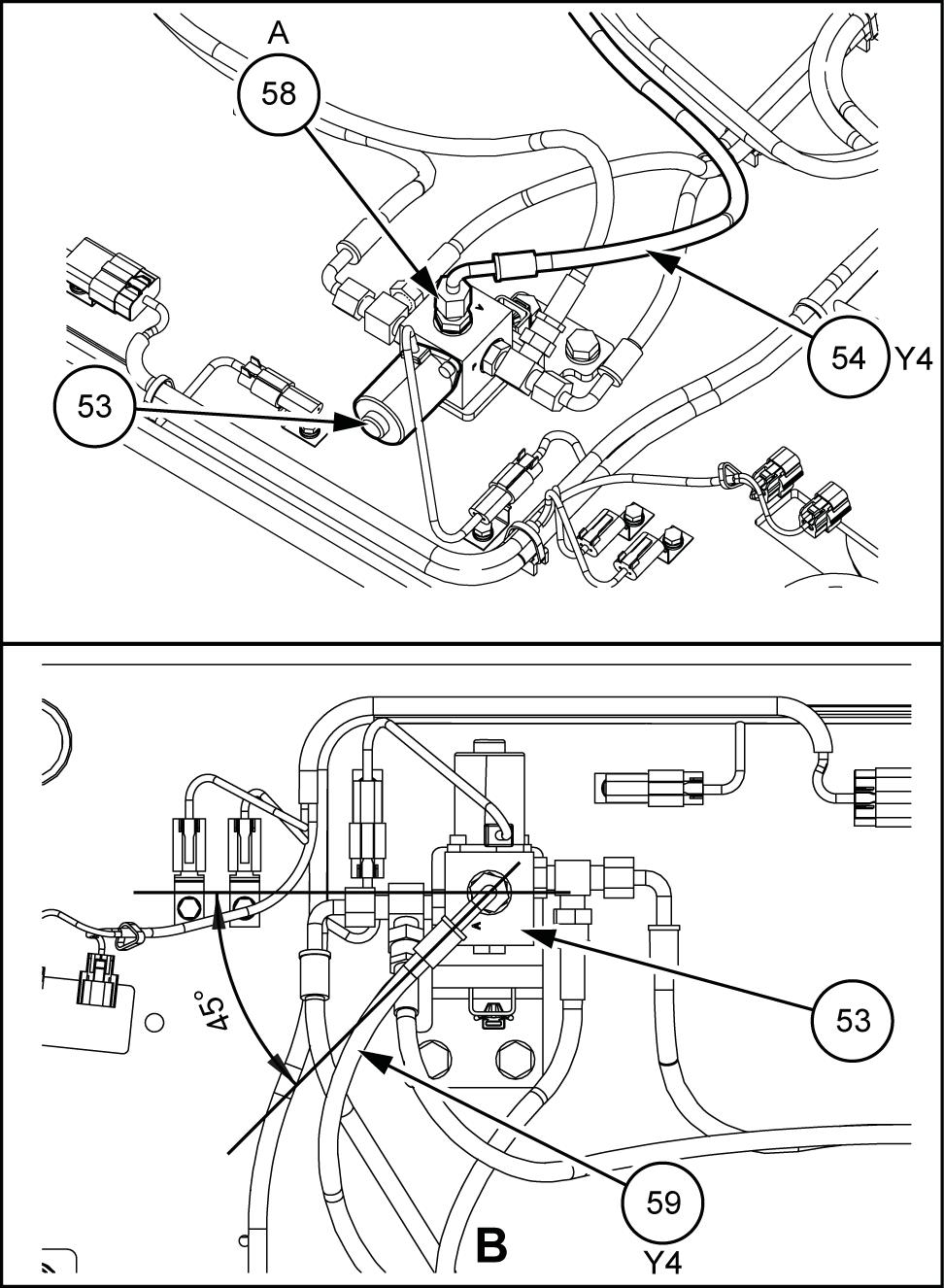
Install the hose adapter (58) the solenoid valve (53) A SMIL15CEX2565BB
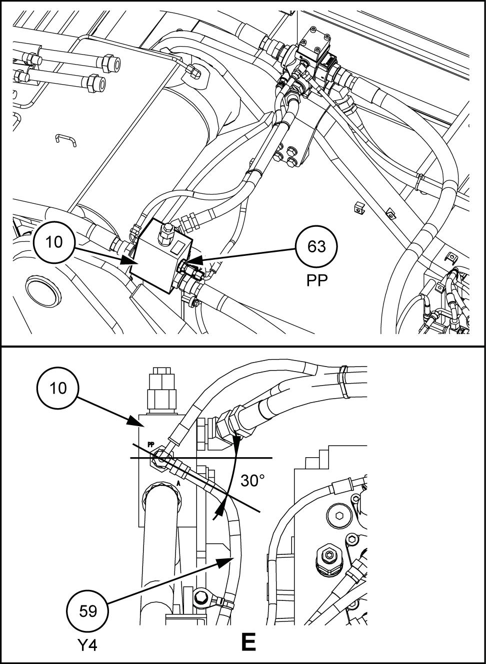
14. Install the tee (63) the shut - f valve (10) port.
Connect the solenoid valve (53) A port and the shut - f valve (10) PP port with the assembly hose (59) SMIL15CEX2851BB
Fasten the assembly hose (59) (Y4) with the clamp with band (66) and special bolt (67)

• T ightening torque: 25.431.4 N·m ( 18.723.2 )
Fasten the assembly hose (59) (Y4) three tions with the mount clamp (68) and wire band (69)
Install the elbow (65) the three - direction valve (17)
Connect the shut - f valve (10) port and threedirection valve (17) port with the assembly hose (61)

17.
Install the elbow (65) the shut - f valve (10) SMIL15CEX2852BB
Install the tee (63) the three - direction valve (17)
Connect the assembly hose (61) (D1 the shut - f valve (10) port and three - direction valve (17) and then fasten with two wire bands (69)


19. Install the hose adapter (75) the hydraulic tank (*4) . Connect the three - direction valve (17) port and hydraulic tank (*4) with the assembly hose (62)


Fasten the assembly hose (62) (D12) two locations with the wire bands (69)
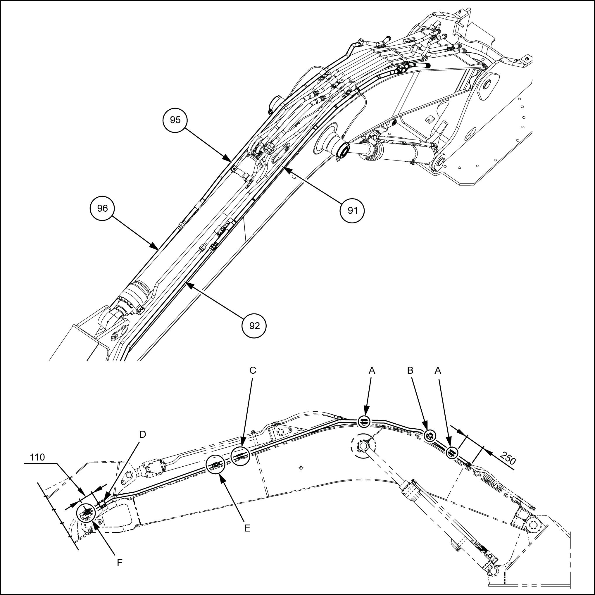
Fasten the assembly hose with four mount clamps (77) , four Phillips pan head screws (78) , and four wire bands (79)
• Fasten the assembly hose with four wire bands (71)
Fasten the assembly hose together with the pilot control
Install the two pressure sensors (70) the reducing valve (43) .
Fasten the assembly hose with four wire bands (71) .

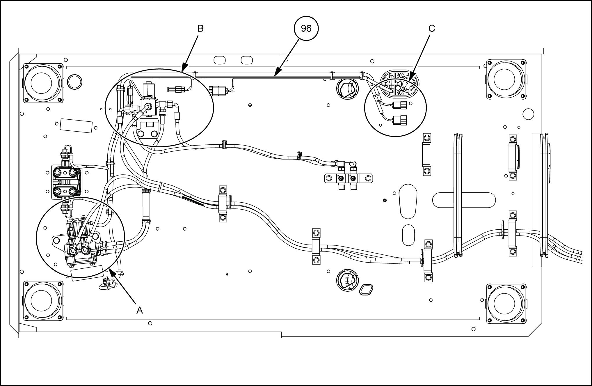
Harness installation - Proportional control

SMIL15CEX2573FB 1
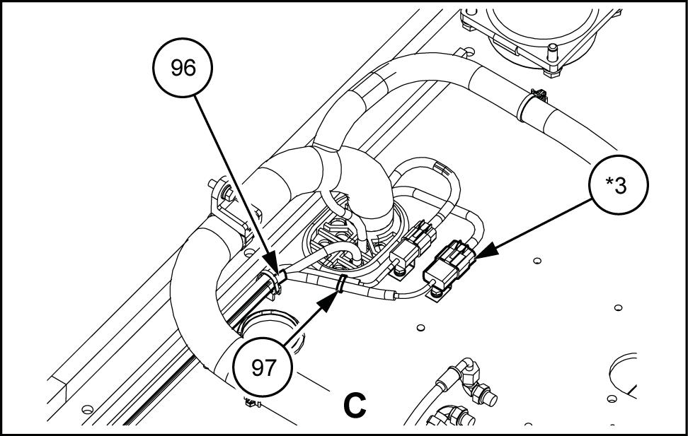
Connect the wire harness (96) and the reducing valve (*1)


SMIL15CEX2575AB 3
Route the wire harness (96) shown the diagram.
Fasten the wire harness (96) six locations with six wire bands (97)
SMIL15CEX2576BB 4
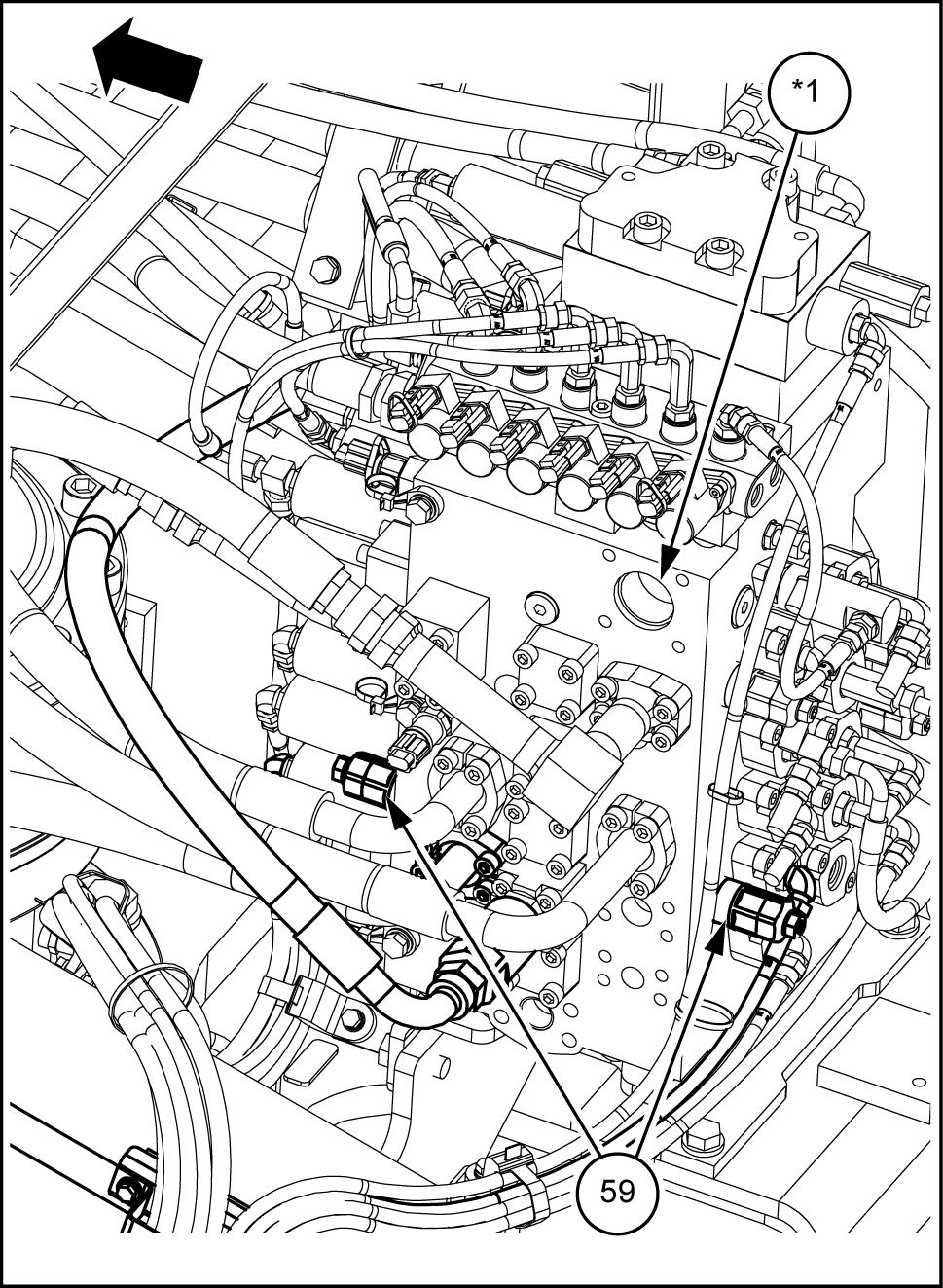
Connect the wire harness (96) and solenoid valve (*2) shown the
Fasten the three couplers the wire harness (96) with one clip (98) each and one bolt (99) SMIL15CEX2577AB
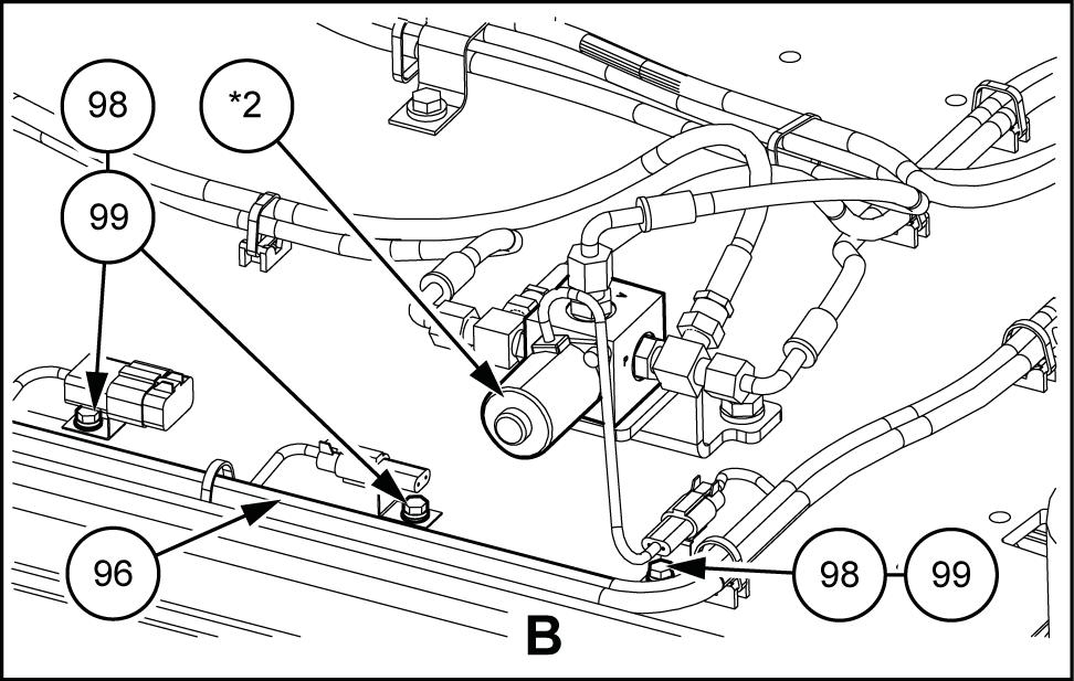
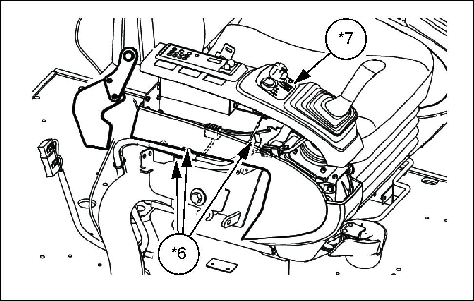
Connect the wire harness (96) connector - pin) the frame main harness (*3) and fasten with the wire band (97) SMIL15CEX2578AB
Extend the wire harness (96) the floor side from der the

Connect the wire harness (96) connector (16 - pin) the cab main harness and fasten with the wire band (97)