3 minute read
Electric ramp: emergency operation

from Mercedes Benz Citaro, Citaro LE, Citaro K, Citaro G, CapaCity Operating Instructions Manual - PDF
Practical advice
Electric ramp: emergency operation
Advertisement
Electric ramp: emergency operation Important information
Warning
Risk of accident and injury caused by inadvertent vehicle movement or sudden braking. ▶ Do not activate the bus stop brake unless the bus is stationary, do not use it as a means to brake a coasting bus to a halt. ▶ Always apply the parking brake before the driver's area is vacated. ▶ Apply the parking brake at bus stops on uphill or downhill gradients steeper than 15 %.
Warning Risk of entrapment and crushing.
Reaching in between mechanically operated parts may result in serious injuries due to the severing or crushing of body parts. ▶ When components are being moved, all limbs and other parts of the body must be outside the range of movement of the mechanisms. ▶ Supervise the danger area. ▶ Before setting components in motion, secure the mechanism against unauthorised access throughout its entire range of movement.
Emergency operation of the internal ramp Stowing the tread plate, internal ramp
▶ Observe ( → page 370) the safety precautions at the start of this section. ▶ Switch off the ignition.
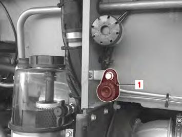
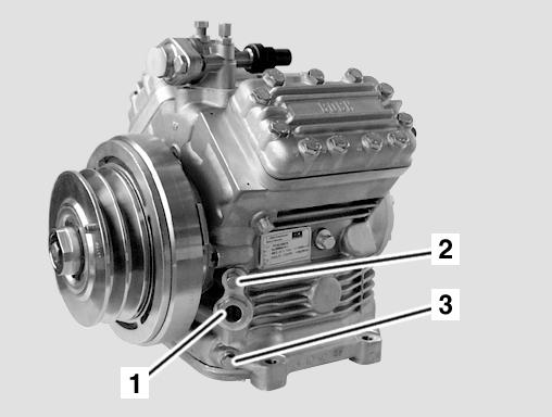
M54.00-2572-71 ▶ Position emergency crank (2) on fixture point (1).

M54.00-2573-71 ▶ Turn emergency crank (3) anti-clockwise. ◁ The tread plate retracts.
Emergency operation of the cassette ramp Deploying the tread plate

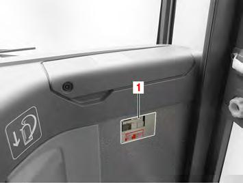
M86.00-0594-71 ▶ Observe ( → page 370) the safety precautions at the start of this section. ▶ Switch off the ignition. ▶ Open flap (1). Practical advice
Electric ramp: emergency operation

M86.00-0595-71 ▶ Pull release lever (2).
Note
There is a picture label providing instructions for emergency use on the inside of the flap.
Practical advice
Electric ramp: emergency operation

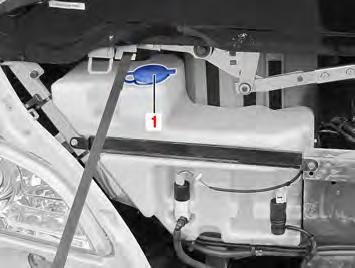
M86.00-0597-71 ▶ Pull release lever (2) out approximately 100 mm. ◁ The tread plate moves out of the cassette slot.

M86.00-0598-71 ▶ Grasp the tread plate by the front edge and pull it out.
Arranging the tread plate

M86.00-0599-71 Before the tread plate is placed in position, lever (2) must be retracted (arrowed).

M86.00-0600-71 ▶ Grasp tread plate (3) at the positions (arrowed) and lift it up to the doorway edge.
Note
The rubber profile of the tread plate must rest uniformly along the doorway edge.

M86.00-0601-71 To engage the tread plate, it is necessary to pull lever (4). Lever (4) should be pulled until notch (B) is aligned with marking (C). Practical advice
Electric ramp: emergency operation

M86.00-0602-71 Toggle lever (A) should be at an angle of approximately 20° to the tread plate. For safe loading, notch (B) must be aligned with marking (C).
Practical advice
Electric ramp: emergency operation
Load testing

M86.00-0603-71 ▶ Step onto tread plate (3). ◁ Under load, the tread plate must not drop.
Stowing the tread plate

M86.00-0604-71
Warning
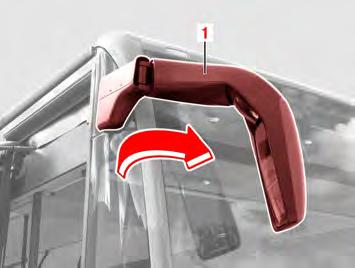
Risk of accident and injury caused by uncontrolled deployment of the ramp following an emergency operation. ▶ Slide the ramp in fully until the flap on the front of the ramp is fully closed. ▶ Move lever (4) in the direction of the arrow.

M86.00-0605-71 ▶ Lower tread plate (3) by hand.

M86.00-0606-71 ▶ Grasp tread plate (3) by the edge (arrowed) and slide it in.