2 minute read
7.4 Replacing Header Drive Chain Sprockets

SECTION 7 – SERVICE
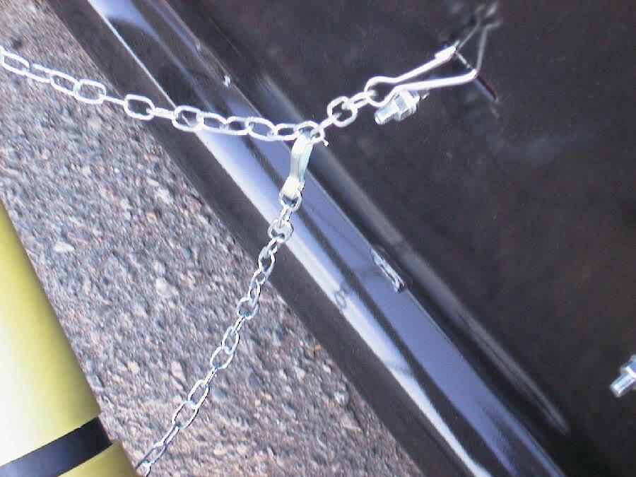
P00049
Chain Clip Attachment
NOTE: After removing drive shaft from the combine be sure to place it onto the storage bracket. See following photos.
Driveshaft Storage Bracket
Drive Shaft in Storage Position 7.4 REPLACING HEADER DRIVE CHAIN SPROCKETS
DANGER: Lower header to the
ground or raise and engage feeder house locks, shut-off combine, remove ignition key, and wait for parts to stop moving before performing this adjustment
A) Chain Removal


a) Remove left shield. See Opening Header
Side Panels. b) Release the tension in the chain. See Header
Drive Chain Adjustment.
c) Remove the connecting link in the chain and take off the chain.
P00083
Drive Chain Links
B) Large Sprocket Removal
a) Remove the cotter pin, thrust washer and 11/8 inch castle nut from the large sprocket shaft.
b) Remove the two M12 bolts from the sprocket.
c) Remove the sprocket. A puller may be required to aid in the removal.
d) Clean and inspect components. Replace any worn or damaged parts.
43
SECTION 7 – SERVICE
C) Large Sprocket Installation
a) Apply a coating of anti-seize compound to the drive shaft and sprocket splines.
b) Place the sprocket onto the drive shaft.
c) Install the thrust washer and castle nut.
Tighten until sprocket has slid on as far as it can go and the bearing is properly sandwiched between the sprocket hub and shaft shoulder. A torque of 55-65 Nm (41ftlb – 48ft-lb) should achieve this. Back off castle nut a quarter turn.
d) Install the M12 bolts through the sprocket and secure with the M12 Unitorque nuts.
Torque to 125-150 Nm (93ft-lb – 112ft-lb).
e) Torque the castle nut 360-400 Nm (265-295 ft-lb).
f) Install the cotter pin and bend end around nut. If the castle nut hole does not align up with the shaft hole tighten until alignment is achieved. DO NOT loosen the nut to achieve alignment.
D) Small Sprocket Removal
a) Remove the cotter pin, shim(s), washer and
M12 castle nut from the small sprocket shaft.
b) Remove the sprocket. A puller may be required to aid in the removal.
c) Clean and inspect components. Replace any worn or damaged parts.
NOTE: Take note of the location of the spacer and number of shims if or when removing them from the shaft.
E) Small Sprocket Installation
a) Apply a coating of anti-seize compound to the drive shaft and sprocket splines.
b) Install the spacer and shim(s) back onto the shaft. Be sure to refer to the note in the removal procedure.
c) Install the new sprocket onto the shaft.
NOTE: Setscrews are not required for this connection.
d) Check sprocket for alignment. Allowable misalignment is ±1.5mm (1/16 inch). Align the sprocket by adding or removing shims from behind the sprocket.
NOTE: Each shim is 1.5mm (1/16 inch) thick. Removal or installation of additional shims may be required.
e) Place the remaining shims in front of the sprocket. Install washer castle nut onto the shaft and torque to 55-65 Nm (41ft-lb – 48ftlb).
f) Install the cotter pin and bend end around nut. If the castle nut hole does not align with the shaft hole tighten until alignment is achieved. DO NOT loosen the nut to achieve alignment.

Header Drive Chain
44