1 minute read
SHIM PACK CALCULATIONS


SHIM PACK CALCULATIONS : - 64 -
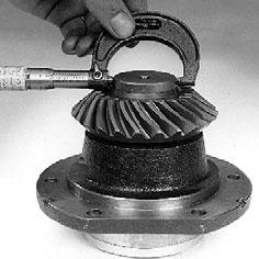
- Measure the distance from the output housing mounting face to the previously measured diameter on the input shaft.
Measurement F :

- For this formula the mounting dimensions marked on gears will be called (See fig. 28). • Input gear = Measurement G • Output gear= Measurement H Cote A Cote B
- The shim pack thickness required for the input shaft assembly is calculated as follows : D x 0,5 + E = J A + G - J = Required shim pack thickness (X) Cote C Cote D
• Picture 34 = measurement A • Picture 58 = measurement D • Picture 62 = measurement E • Picture 28 = measurement G

- The shim pack thickness required for the output shaft assembly is calculated as follows : B x 0,5 + F = K C + H - K = Required shim pack thickness (X’) Cote E Cote F
• Picture 44 = measurement B • Picture 47 = measurement C • Picture 64 = measurement F • Picture 28 = measurement H
- Select the shims required to give the thickness calculated and refit input and output shaft assemblies into the case. Cote G Cote H
- Torque the 12 bolts to 39 - 58 Nm.
List of calculated shim packs.

Dimensions (mm) References Dimensions (mm) References 11.57-11.59 702 779 11.81-11.83 604 780 11.60-11.62 702 780 11.84-11.86 604 781 11.63-11.65 604 774 11.87-11.89 604 782 11.66-11.68 604 775 11.90-11.92 604 783 11.69-11.71 604 776 11.93-11.95 604 784 11.72-11.74 604 777 11.96-11.98 604 785 11.75-11.77 604 778 11.99-12.01 702 781 11;78-11.80 604 779 12.02-12.04 702 782