24 minute read
Ⅳ ter AChapdjustment of Tractor

from Mahindra Tractor JINMA-200 JINMA-204 JINMA-250 JINMA-254 JINMA-300A JINMA-304A Operators Manual PDF

1. Adjustment of clutch
Due to continuous wear of parts during operation of the clutch, clutch slip and clutch incomplete disengagement will happen, which can't make the tractor work normally; therefore adjustment of clutch should be timely made.
1) Adjustment of dual stage clutch
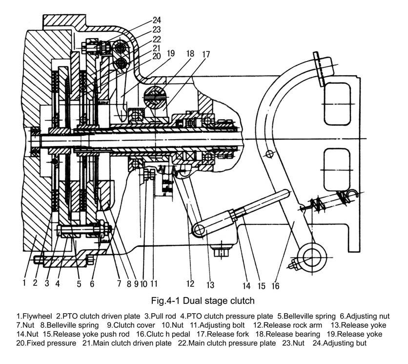
Fig. 4-1 is connection-controlled dual stage clutch. It mainly consists of three parts: driving part, driven part and controlling part. Driving part rotates with the engine flywheel; only when the clutch engages can the driven part rotate with the engine.
Dual stage clutch should be adjusted on a fixture. The adjusting steps are as follows: Adjust the length of adjusting bolt (11) to make the distance between 3 release levers (19) and the end faces of PTO clutch pressure plate (4) is 96.8mm, and the distance difference between 3 release levers and PTO clutch pressure plate is no more than 0.1mm; after adjustment × tighten it with nut M101.
When adjusting the free travel of the clutch pedal (Fig. 4-1), firstly adjust the length of clutch push rod (15) to ensure that the clearance between end faces of three release levers and ± release bearing is 2.50.5mm and the idle travel of release rock arm is 3.5-5mm; after adjustment tighten it with nut M10.
Position limit adjustment of working travel of clutch pedal: loosen nut (10), then turn adjusting bolt (11) to make the working travel under release rock arm (12) is 25mm, then tighten nut (10).
2) Adjustment of single stage clutch
Fig.4-2 is single - disk and dry single stage clutch . It is made up of clutch spring(1), clutch driven plate(2) ,clutch pressure plate(3) ,release lever(6) ,adjusting nut (7) ,release bearing (9) and its operation mechanism.
The adjuting methods of single stage clutch are as follows:
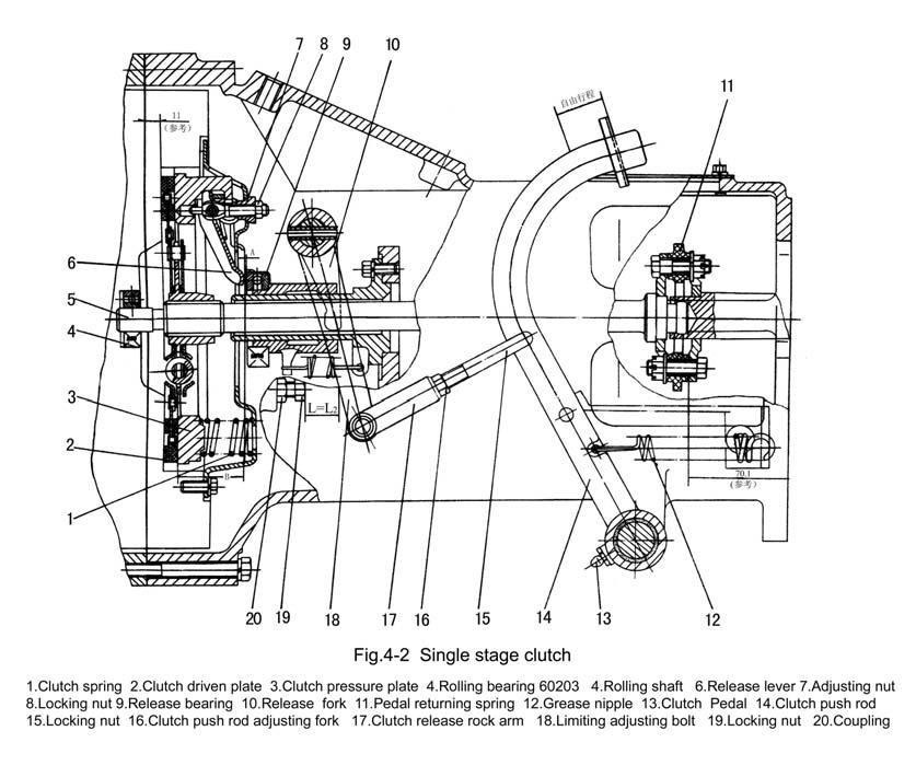
A. Position adjustment of release levers
In reassembling the clutch,turn adjusting nut(7) to make the distance between working faces of release levers and the working face of pressure plate be B=45mm. When the clutch engages, the gap A=2-3mm between release bearing (9) and release levers (6) should be kept; and 3 working faces of the release levers (6) should be in the same plane , the allowed deviation is 0.25 mm.
B.Free travel adjustment of clutch pedal
Turn push rod adjusting fork (16) to change the effective length of push rod (14) until it reaches the free travel of the clutch pedal L=8-12 mm (while the corresponding free travel under the release rock arm (17) is L1=3.5-5.5 mm ).
C. Position limit adjustment of working travel of clutch pedal
Turn limiting adjusting bolt (18) until the working travel under release rock arm(17) is L2=13-17mm . In operation the free travel of the clutch pedal should be often checked and ensured.
2. Adjustment of main drive
1)Preload adjustment of the conical bearing
During assembling there should be some preload on two conical bearings (3) 2007111 (on two ends of differential) and two conical bearing 27305(10) (on second shaft) (Fig.4-3) for reducing axial displacement and increasing supporting rigidity of the spiral bevel gears under operation. After operation for a period, as the conical bearings wears, the former preload will disappear gradually, and moving clearance will occur between the two conical bearings when the two moving clearance is more than 0.1 mm, the conical bearings should be preloaded again.

A. Preload adjustment of second shaft conical bearing
Adjust the screwing tightness of the locking nut (11) near the bearing until the torsional friction torque of the second shaft (9) is 0.7-1.1 N.m. After adjustment, insert locking slice (12), then tightly screw the second locking nut (11).
B. Preload adjustment of differential conical bearing
Insert the adjusting shims (5) in same quantities between the two sides of transmission box (2) and the bearing seats (4) of conical bearings, then tightly screw the bolts (6) of the bearing seats; and turn second shaft (9), if the torsional torque is 0.4-0.76 N.m more than that of the condition that the differential is not mounted, then the preload is suitable. In such case, any axial displacement of the crown gear should not exist with the axially applied thrust.
2) Adjustment of meshing prints and backlash of the spiral bevel gears
A. Standard of meshing backlash and meshing print
The required mesh backlash is 0.1-0.25 mm. The ideal mesh prints distribute in the middle of the working teeth surface and are slightly near the small end of the teeth; meshing prints are like spots; meshing print height is not less than 50% of tooth height, the length of meshing print is not less than 60% of tooth length.
B. Inspection of mesh backlash and mesh print a. Inspection of mesh backlash b. Inspection of mesh print
There are two methods of inspection: One is dial gauge inspection. During measuring, put contact terminal on the teeth surfaces of big ends of bevel gear, and fix bevel pinion, swing bevel gear in rotating direction; if the reading of the dial gauge is 0.14-0.3mm(circular clearance), the backlash is correct. The other method is as follows: Using a lead wire of 15∽ 20mm long and 0.5mm thick or a fuse bent into "" shape, put it between the unmeshed teeth surfaces of the bevel gear and pinion(i.e. between the convex surface of the bevel pinion and the concave surface of the bevel gear) and rotate the gear pair, then the thickness of the extruded part where the lead slice is near the big ends of the gears is the vertical gear backlash. The gear backlash should be among the range of 0.1-0.25mm(vertical backlash). It is better to measure three or more points well distributed along the circumference of the bevel gear and take the average value of measuring the gear backlash in the three or more points.
Coloring method is adopted in the inspection of the mesh print. Smear red-lead paint evenly on the faces of the bevel gear teeth. Turn the bevel gears several times until the distinct contact traces are imprinted on the teeth faces of the bevel pinion. The print imprinted on the teeth faces of the bevel pinion is mesh print. As the spiral direction of the bevel pinion is righthanded, when the tractor forwards, the force is applied on the concave face of the bevel pinion, the readlead paint should be smeared on the convex face of the bevel gear; while the tractor reverse, the force is applied on the convex face of the bevel pinion, the red-lead paint should be smeared on the concave face of the bevel gear.
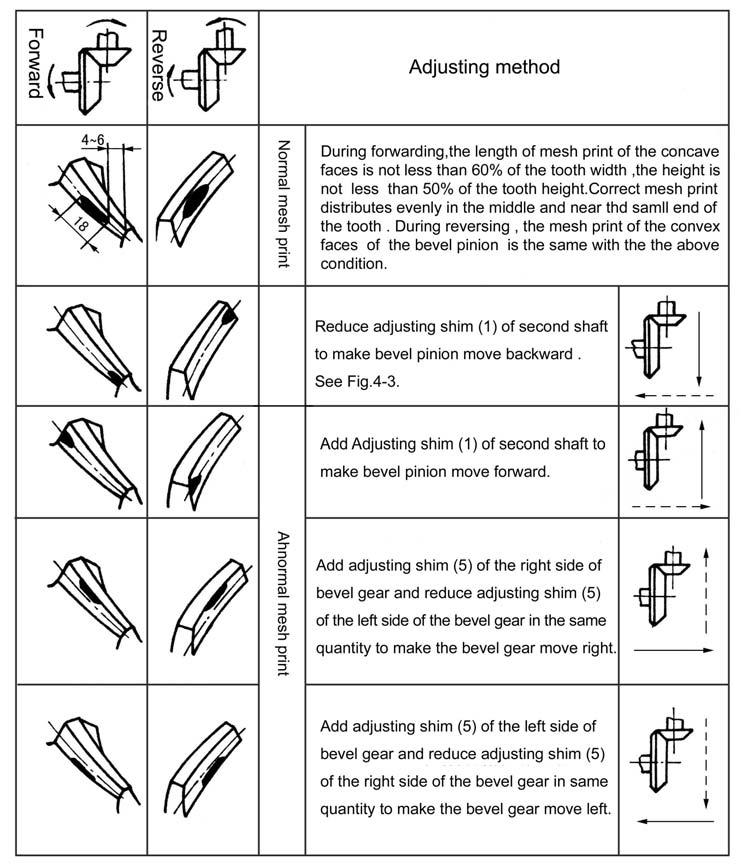
Table 4-1 Adjustment of mesh print of bevel gear
Note: solid line arrow shows the adjustment of mesh print and dotted line shows the adjustment of mesh backlash.
c. Adjustment of mesh backlash and mesh print
During adjustment, the bevel gear and pinion axially moving will change both mesh backlash and mesh print. If the mesh print requirement is contradictory to mesh backlash, correct mesh print should mainly be ensured, and the adjustment range of mesh backlash can be enlarged (Especially when the gear and bearing wears and the readjustment is needed, the backlash can be enlarged). But the mesh backlash should be not less than 0.1mm.
During normal operation of the tractor, the normal mesh backlash and mesh point will both change, under this condition, so long as teeth faces contact is normal, only the mesh backlash increases, and this increase of backlash due to gear wear need not be adjusted. But after the overhaul of the tractor or when replacing a new pair of main drive gears or bevel bearing, the mesh print and backlash should be ensured at the same time by careful adjustment.
Note: As the bevel pinion and the bevel gear are a pair of matched gears, be sure not to make pairs in disorder. The spiral bevel gears should be replaced together with the bearings, if possible. Otherwise, it will affect their service life.
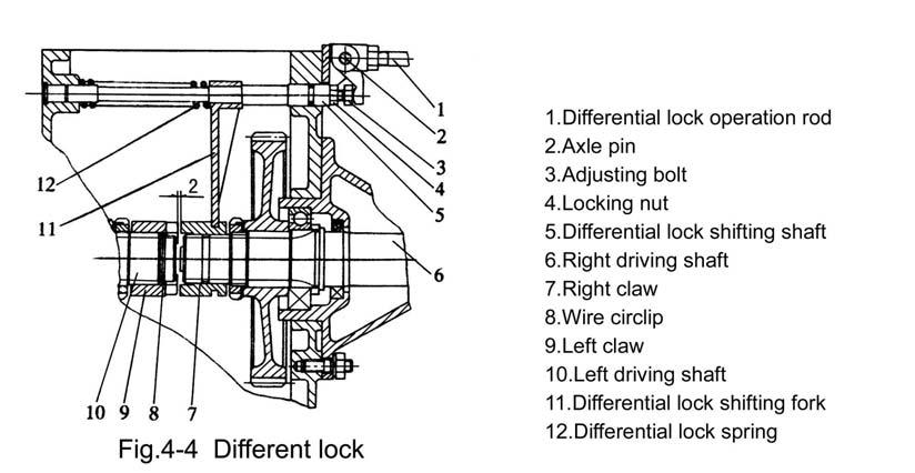
3. Adjustment of differential lock
The differential lock can be adjusted through bolt (3) and nut (4). During adjusting, the gap between left claw (9) and right claw (7) should be about 2mm. Screw in or out the bolt (3) to increase or reduce the gap. After the adjustment has been done, use nut (4) to tighten bolt (3). (Fig.4-4)
4. Adjustment of brake
After the tractor has worked for a period, the wear of the friction disc of the brake makes the gap between friction disc and brake drum or friction disc and brake case and brake cover increase and affect the brake performance. Excessive free travel will cause brake ineffectiveness. So the brake should be regularly adjusted to ensure the safety walk of the tractor. When one of the following faults of the brake appears, adjustment should be done in time. (No matter the tractor is new or old).
a. Free travel of brake pedal is excessive and cause brake ineffectiveness.
b. Free travel of brake pedal is too small and keep the brake in semi-braking state; the brake case also generates heat.
c. Left and right braking force is unidentical and tractor yaw motion appears.
1)Adjustment of block brake(shoe brake)
A. Free travel adjustment of brake pedal is the displacement measured from the highest position of the pedal ,when resistance is felt by pressing the pedal .The travel should be in the range of 55-65 mm (Fig.4-5) .During adjustment ,firstly loosen the locking nut (9) on brake pull rod (8) and change the length of the brake pull rod ,then press the brake pedal (5) from its highest position untill the displacement it 55-65mm and the gap between brake drum (13) and brake shoe(12) is eliminated . Make the left and right brake pull rod adjustment be identical ,the tighten them with locking nut (9) (Fig.4-5).
B.Tractor yaw motion adjustment
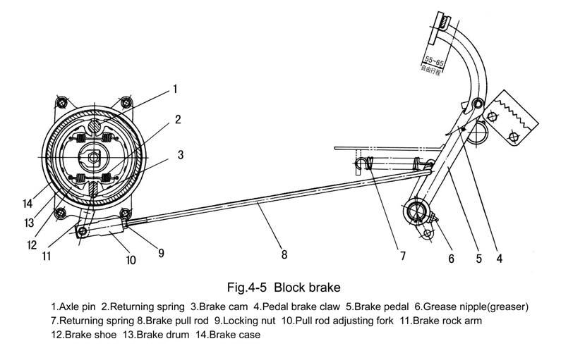
While left and right brake adjustment is unidentical and the tractor running in high speed is braked in emergency , unidentical tyre print length (left and right ) and yaw motion appear .In such case ,the brake pull rod should be shortened in the side with short print length of tire ,or vice versa, to make both sides of the driving wheels to be braked simultaneously and reliably ,then retighten the locking nut (9) . Subsequently ,check in the 3rd gear firstly ,after above adjustment has been done ,the check in the 4th gear again.
2) Adjustment of disc brake
A. Free state adjustment of disc brake pedal is the displacement measured from the highest
Loosen the outer locking nut M10 (5) on adjusting rod (1) and turn the inner nut M10 (4) to change the mounting angle of the rock arm (2) through the longitudinal motion of the self-position cushion (3) and ensure that the central connecting line of the upper and lower holes inclines to rear from the plumb line. After adjustment, lock it with locking nut (5). (Fig.4 -6)
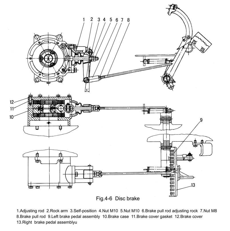
B. Travel adjustment of brake pedal
Loosen the locking nut (7) on pull rod adjusting fork (6) and turn brake pull rod adjusting fork to change the length of the pull rod (8) until the displacement (from the highest position of the brake pedal to friction disc assembly being completely braked) of the brake pedal is 85-95mm. When the left and right pedal are locked together, stepping on the pedals can simultaneously brake the left and right wheels; after adjustment, lock it with nut (7). (Fig.4-6)
If the above adjusting range can not perfectly make the free state and brake state out, they can be adjusted through increasing or reducing the brake cover gaskets (11) between brake cover (12) and brake case (10). If the brake travel is too small, increase the gaskets; if the brake travel is too big, reduce or remove the gaskets. (Fig.4-6)
C. Brake yaw motion adjustment
Refer to the adjustment of shoe brake
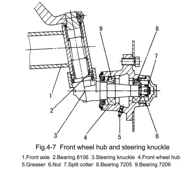
5. Adjustment of front axle
1) Axial clearance adjustment of front wheel bearings
The normal axial clearance between front wheel bearings (8) and (9) is 0.1-0.2mm(Fig.4 -7). During operation, when the clearance is more than 0.4mm, the front wheel will swing to left or right during walking; and the bearings are easily broken by shock load, so adjustment should be made timely. During adjustment, firstly support the front wheels off the ground, and dismantle the bearing cover and pull out the split cotter on nut (6), then screw nut (6) until the bearing clearance is eliminated, and return the nut (6) in 1/15-1/7 turn, then lock the nut with split cotter, and assemble the bearing cover.
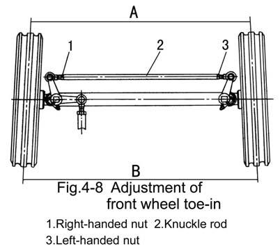
2) Adjustment of front wheel toe-in
During the operation of the tractor, the front wheel toe-in will change due to deformation and wear out of the parts of steering mechanism and front axle. If the toe-in is not adjusted in time, the wear of the front wheel will accelerate. The adjustment steps of toein are as follows: a. Stop the tractor on level ground, place the front wheels on rectilinear walking position. b. Measure the distance A and B between the two wheels (Distance A is the distance between the forefront of the two wheels. B is the distance between the rearmost ends of the two wheels.) at the same horizontal plane through the centers of the two wheels circumference. c. Loosen the locking nuts (1) and (3) on both sides of the knuckle rod (2); turn the knuckle rod to make B-A=4-10mm, then retighten knuckle rod (2) with nuts (1) and (3).
6. Adjustment of front drive axle
1) Adjustment of main drive (Fig.4-9)
During assembling, choose the suitable bearing seat gasket (9) of driving bevel gear and adjust the adjusting nuts (3) on the both sides to make the mesh backlash of the gear pairs of the main drive be 0.15-0.30mm, and ensure the contacting area, i.e. the meshing contact traces of the gear pairs should be adjusted to the middle of gear tooth faces and slightly nearer to the small end; and should also ensure that no axial movement of the bearings on either end will appear, and that the differential assembly could turn freely. Adjust the position of the concave slot of the nut to make the locating plate of the cover be inserted smoothly, then lock the nut.
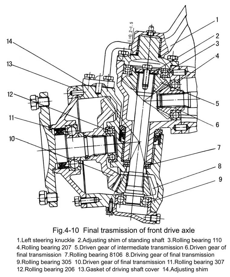
2) Adjustment of side reduction gear pairs (Fig.4-10)
During assembling, choose gasket (13) of driving shaft cover to keep the mesh backlash of side reduction gear pairs among 0.2-0.4mm, and ensure meshing contact traces.
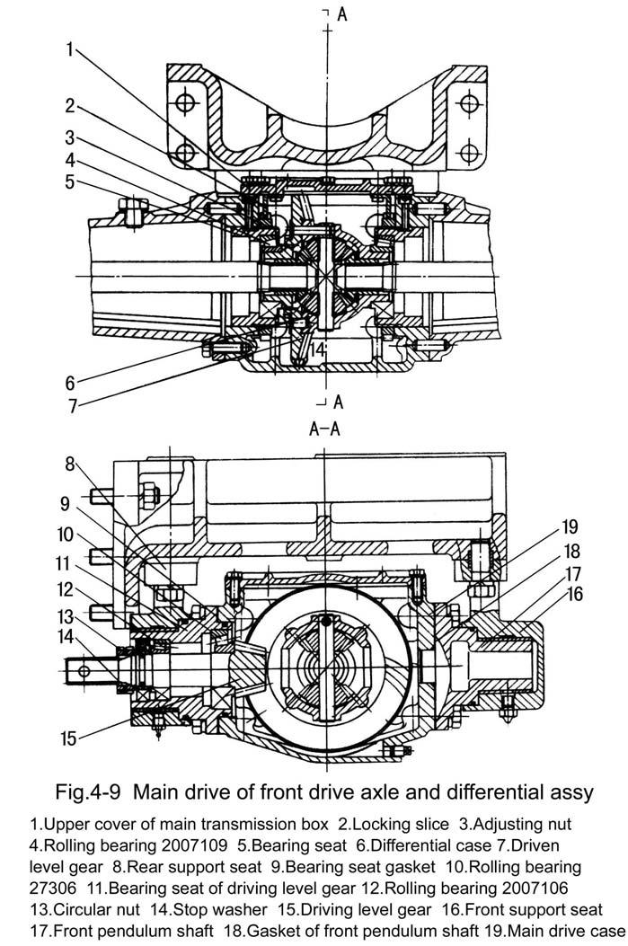
3) Adjustment of intermediate driven gear pairs (Fig.4-9)
During assembling, choose adjusting shim (2) of the standing shaft to keep the mesh backlash among 0.2-0.4mm and ensure meshing contact traces.
7. Adjustment of wheel tread
1) Adjustment of front wheel tread
The front wheel treads of Agracat Series Tractors have the following two types: adjustable wheel tread and non-adjustable wheel tread. The adjustable wheel tread is adjusted in step through extension sleeve housing. The adjusting range is 970-1270mm. Every step clearance is 100mm.
2) Adjustment of rear wheel tread
The wheel tread of the back wheels can be steplessly adjusted through changing or turning over the fixed position of the driving wheel hubs in the driving shaft. It can be also adjusted in steps through turning over the wheel rims or exchanging the right and left driving wheels.
The adjustment range of the first-step wheel tread is L1-L2; the normal wheel tread is L2. The adjustment range of the second-step wheel tread is L3-L4 (see Fig.4-11). Numerical Ⅰ value of L1-L4 can be referred to in chapter .
8. Adjustment of steering gear
There are three kinds of steering gear of Agracat Series Tractors: crankpin type (Fig.412), circulating ball type (Fig.4-13) and hydraulic steering gear (Fig.4-14).
1) Adjustment of crankpin type steering gear (Fig.4-12)

A. Adjustment of bearing clearance
In order to ensure the normal work of the steering gear, the clearance of the bevel bearings 7204 on either end of steering worm should be adjusted. When the bearings wear out to make the axial clearance increase, the clearance should be adjusted timely; i.e. make the upper and lower moving play of the steering worm be not more than 0.1mm through increasing or reducing the quantity of adjusting shim (11).
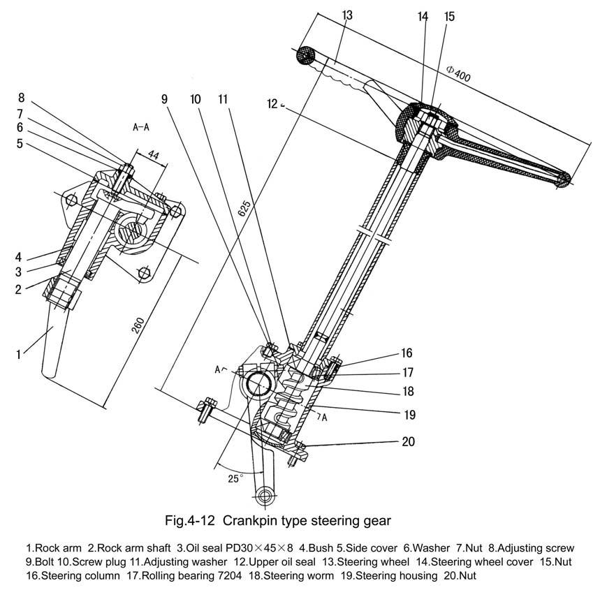
B. Adjustment of mesh clearance of steering worm and crankpin
During operation, the mesh clearance will increase due to the wear out of the steering worm and crankpin, and the idle angle of the steering wheel also increases. When the idle ° angle of the steering wheel is more than 25(or the arc length along the outside of the steering wheel is more than 90mm), the clearance should be adjusted.
Adjusting method: loosen nut (7), turn adjusting screw (8) to make rock arm shaft (2) move axially and therefore the mesh clearance is changed.
When the rock arm shaft is in middle position, the free travel of steering wheel outside is ° 50-55mm, i.e. the idle angle of the steering wheel is no more than 15, then the adjustment is suitable. After adjustment, lock nut (7).
2) Adjustment of circulating ball type steering gear
A. Adjustment of bearing clearance
In order to ensure the normal work of the steering gear, the clearance of the bevel bearings 7304 on both ends of the rock arm shaft should be adjusted. When the bearings wear out and the axial clearance of the bearings increases, the clearance should be adjusted in time; i.e. make the upper and lower moving play of the steering worm be not more than 0.1mm through increasing or reducing the quantity of adjusting shim (7).
B. Adjustment of mesh clearance of rock arm shaft (with steering worm and nut assembly) and fan teeth of rock arm shaft.
During operation, the mesh clearance will increase due to the wear out of fan teeth of the rock arm shaft (with steering worm and nut assembly) and the idle angle of the steering wheel will also increase; so adjustment should be made in time. Loosen nut (2), turn adjusting screw (1) to make rock arm shaft move axially and therefore the above mesh clearance is changed
3) Construction and adjustment of balance string type hydraulic steering gear
A. Working principle of balance string type hydraulic steering gears BZZ series balance string type hydraulic steering gears are adopted in the hydraulic steering gears of Agracat series tractors; their structure diagram is as Fig.4-14. It is mainly made up of steering control valve and steering measuring device.
Valve sleeve of the steering control valve (6) is connected with valve core (7) through plug (5), and spring leaf is fixed in the middle of the valve. The hole in the valve core (for mounting the plug) is a little bigger than the hole in valve sleeve (6), so they can rotate relatively, the outside of the valve core connects with connecting piece (1).
The stator (13) and rear cover (10) of steering measuring device are fixed together with valve body (3) of steering control valve by bolt. Rotor (9) connects with valve sleeve (6) through connection shaft (8) and plug (5). Rotor (9) and stator (13) are balance string type needle wheel mesh pair. The rotor has 6 short outer pendulum string curve teeth of equal distance, while the stator has 7 arc needle teeth. During working, the stator is still and the rotor rotates round the center of the stator at the radius of a certain eccentric distance. When the rotor rotates round center of the stator (revolution), it also rotates round its axial line in opposite direction (rotation). As the rotor makes a circuit and it can rotates round the stator center for -6/(7-6)=-6 circuits, rotor makes one circuits, the oil liquid will be squeezed out × from the teeth slot (67=42), and the displacement at unit volume is large.
B. Adjustment of balance string type hydraulic steering gear.
As the rotating times or circuits of the steering wheel concern the rated displacement of the steering gear, which has been decided during designing; if the radial or axial clearance of the stator and rotor pair is too big to cause no manpower steering, then the rotor and stator pair should be replaced. In other conditions, adjustment is not needed.

9. Construction and adjustment of hydraulic hitch system
Hydraulic hitch system consists of hydraulic system and hitch device. Hydraulic system is an open circulating circuit system controlled by pressure circuit. The hitch device is rearattached 3 point hitch. Hydraulic system mainly consists of semi-separation attachment type hydraulic lifter, gear pump, oil filter and their oil pipes (which connect them together).
1) Working principle of gear pump
The gear pumps attached to Agracat series tractors are CBN model volume type outside mesh gear pumps (Fig.4-15). They are all left handed pumps except the right handed pumps on Agracat-160, 164 tractors. The gear pumps are mounted on the back end face of the right side of the gear case of the diesel engine front, which are driven by engines. The gear pump is made up of a pair of outside mesh shaft gear (5) and (6), gear body (2), sleeve (7) and rear cover (1) and front cover (3).
The working principle of the gear pump is as Fig.4-16. Take left-handed gear pump as example: After starting the engine, the driving gear of gear pump rotates counterclockwise, and the oil enters the teeth from the pressure oil cavity and fill the teeth with oil. The oil entered the pump is surrounded and contained by sleeve, meshed teeth and pump body and two oil cavities which are not connected with each other are formed: suck oil cavity and pressure oil cavity. The gear rotates right cavity (suck oil cavity) and the inner gear teeth return mesh to make the volume between gear teeth increase and form part vaccum, and the oil in the tank is sucked in. Meanwhile the inner gear teeth of left cavity (pressure oil cavity) begin to mesh (teeth into each other) to squeeze the oil among the teeth out of the oil pump.
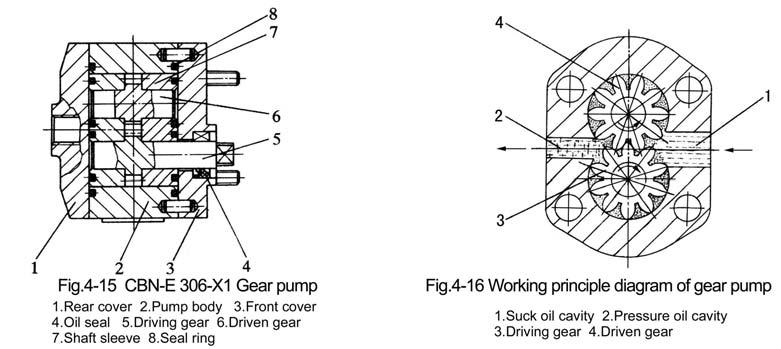
With the rotation of the engine, the oil in the cavity will continuously flow into the lifter through gear pump.
During working, there is pressure difference between the suck oil cavity and pressure oil cavity of the gear pump, the high pressure oil of pressure oil cavity will leak and return to the suck oil cavity along the clearance of the end faces of the gear and sleeve, gear tip and pump body and the clearance formed by bad gear mesh; which will cause pump volume loss and the heat of the hydraulic system. Too much volume loss will not make the gear pump form normal working pressure; if seriously, the gear pump can't lift the implements.
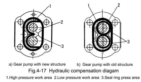
In order to reduce the volume loss of the gear pump, complete floating sleeve is adopted in the pump, which has hydraulic automatic compensation and axial balance construction. During working, the sleeve can float in the pump body; the position of the sleeve is decided by the force applied on the sleeve. The width of the pump body is 0.09-0.18mm bigger than the width sum of gear and sleeve. After mounting, the front and rear cover are pressed tightly on the pump body, the seal ring between the covers are compressed and the sleeve is pressed tightly on the two end faces of the gear, thus not big clearance forms between sleeve and covers. When the oil pressure in the gear rises, the oil pressure apply on the back of the sleeve through the clearance (Fig.4-17), which ensures the good cooperation of the sleeve and gear stick end faces. This action is called hydraulic automatic compensation.
2) Lifter
A. Working principle of valve (simple direction exchange valve)
The structure and working principle of the simple direction exchange valve is as Fig.419.
Main control valve (1) can be respectively put on lifting, neutral and lowering positions throughpulling operation handle (5). When main control valve (1) is on neutral position (Fig-4 -19b), the oil from the oil pump into the direction exchange valve flows back into oil tank through returning oil cavity A according to the flow direction designated by the arrow of the Fig4-19(b). Then the entering oil cavity B and returning oil cavity C of the cylinder are sealed by main control valve (1); the oil cylinder is on seal and lock condition, and the implements are maintained in the fixed position.
When the main control valve (1) is pushed to the lowering position (Fig.4-19d) from neutral position, the returning oil cavity C is opened, the oil in the cylinder is squeezed back into oil tank via returning oil cavity C under the action of the weight of the implement according to the flow direction designated by the arrow in the Fig.4-19d, then the implement is lowering. In such case the oil from oil pump into direction exchange valve still flows back into oil tank through returning oil cavity A.
When the main control valve is pushed to lifting position from neutral position (Fig.419c), the returning oil cavity A closes, while entering oil cavity B opens. Then the oil from oil from oil pump into direction exchange valve enters the oil cylinder via oil cavity B according to the flow direction designated by the arrow in Fig.4-19c, and push the piston forward, then the implement begins to rise.
System safety valve is added and established in the direction exchange valve in order to prevent the hydraulic components from being damaged due to overload during the rising of the implement.
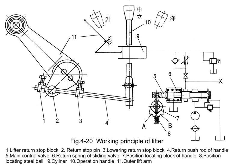
B. Working principle of lifter
Fig.4-20 is a working principle diagram of position adjusting of the lifter (with simple direction exchange valve and high adjustable performance). While pulling the operation handle (10) to lowering position, position locating steel ball (8) falls into lowering the position locating slot B on position locating block (7), meanwhile main control valve (5) moves right to the lower position. The oil in the cylinder flows back into oil tank through main control valve (5), and the implement begins to fall down. With the implement falling gradually, stop pin (2) fixed on the stop plate of the lift shaft and the lift shaft together rotate around the lift shaft counterclockwise, and slip along return push rod (4); after they slip to contact the lowering position limiting stop block (3) fixed on the return push rod, they bring the return push rod (4) move right together; at the same time turn the operation handle until position locating steel ball (8) is pushed out of the position locating slot B. In such case, under the action of tension of return spring (6) of the main control valve, operation handle (10) and main control valve (5) jump back to the neutral position at the same time. And the cylinder stops returning oil, the implement also stops falling. Thus, the falling of the implement depends on the fixed position of lowering return stop block (3) on return push rod (4) i.e. the closer the clearance between lowering return stop block and operation handle is the lower the implement falls. Loosen the tightening bolt of lowering return stop block, the return push rod will lose the ability to make the operation handle return to neutral position. And the main control valve stops at lowering position from beginning to end, while the cylinder is in "floating" state all the time.

While raising the implement, push operation handle (10) to lifting position and then position locating steel ball falls into position locating slot A (Fig.4-20), main control valve (5) moves left to lifting position. The implement begins to rise; with the implement rising gradually, meanwhile, return stop pin (2) rotates around the lift shaft clockwise; when the stop pin slips to contact lifting return stop block (1), drive return push rod (4) to move left, and at the same time rotates operation handle (10) until pull the locating steel ball (8) out of its locating slot. In such case, under the action of the tension of return spring (6), operation handle (10) and main control valve (5) jump to neutral position at the same time. And the oil pump stops supplying oil to the cylinder, the implement stops rising. The raising height of the implement depends on the fixed position of the lift return stop block (1) on the return push rod (4). The closer the clearance between return stop block (1) and return push rod (4) is, the higher the implement rises.
Notes: During operation, if the adjustment is not suitable, it possibly makes the operation handle can not return to its position in time, and can cause parts damage due to overload of hydraulic system.
C. Adjustment of hydraulic lifter

① Adjustment of the utmost lifting position (Fig.4-21)
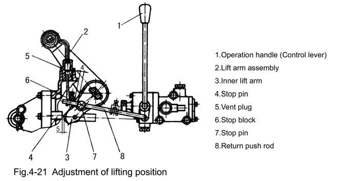
Set the control lever (1) at the neutral position which is illustrated in Fig.4-21. Rotate the lift arm assembly (2) upward, until the clearance between the end of inner lift arm (3) and stop pin (4) is not less than 5mm (insert a steel pad through the hole vent plug (5), control this clearance by the pad thickness). Adjust the clearance between stop block (6) and stop pin (7) to be 9-10mm, then fix the stop block on the return push rod (8) with bolt and nut.
② Adjustment of the lowering position
Set the control lever (1) at the neutral position, rotate the lift arm assembly (2) downwards until the desired lowering position arrives, and adjust the clearance L between stop block (3) and stop pin (4) to be 9-10mm. While in position adjusting, adjustment should be done in ploughing and forwarding; as the plough lowers into the soil and the required ploughing depth is reached, adjust the clearance between lowering stop block (3) and stop pin (4). After adjustment, fix stop block (3) on return push rod (5) with bolt and nut, then raise the implement several times to check the adjustment.
If the implement is provided with a supporting wheel, the floating control needs to be used. Meanwhile, adjust lowering stop block (3) to the position where control lever1 (1) of distributor (valve) will not return to neutral position.
③ Adjustment of lowering speed
During adjustment, the lowering speed of the implement can be adjusted through rotating the adjusting valve bolt (5) (see Fig.4-18). When the lowering speed is suitably adjusted, use check screw (4) to limit the moving range of adjusting valve bolt.
④ Adjustment of safety valve
Safety valve has been adjusted before leaving the factory. In general, dismounting in operation is not permitted anyhow. If the readjustment is necessary, it should be done on special pressure test stand. The oil for test is HC-8(SY1152-77), the oil temperature should be ±℃ controlled as 655. When the press screw plug of safety valve is rotated clockwise, the higher opening pressure is got, or vise versa.
In hydraulic system, as the precision of many parts is high, and the assembly parts have been carefully tested and adjusted, cleanliness of the hydraulic oil, cleaning oil and the environment should be especially paid attention to during operation, maintenance and fixing the breakdowns. Generally free dismount is not allowed.
Notes: Before starting the engine, make sure there is enough oil in the lifter housing, so as to avoid damage to the hydraulic gear pump.
10. Use and adjustment of air brake device of trailer

In order to ensure safety of the trailer transportation of the tractor and achieve the aim of prompt stop of the tractor and trailer, air brake system is mounted on the tractor. The system is made up of air compressor (1), receiver (5), brake valve (4), air pressure gauge and pipes (Fig.4-23).
1) Working process of air brake device of trailer
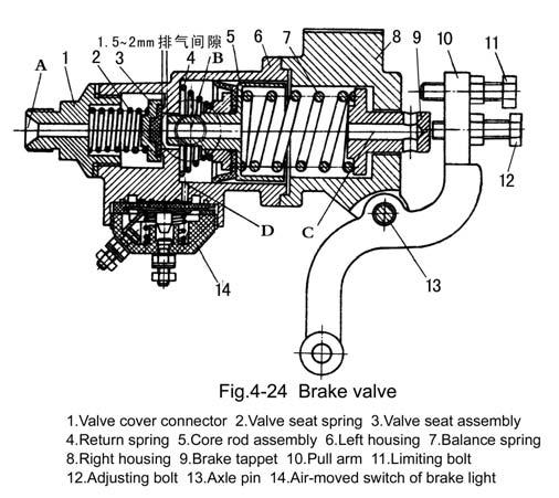
Air brake trailer is braked through the compressed air driving the brake hung on the trailer wheels. Firstly the compressed air is conveyed to receiver from air compressor through pipes, then is conveyed to the brake air chamber of the trailer wheels through air-bleed hole (hole B in Fig.4-24) of the brake valve. When stepping on the brake pedal, through the connecting rod (8 in Fig.4-23) driving the pull arm 10 of brake valve (Fig.4-24) to rotate around axle pin 13 to make adjusting bolt 12 press down brake pull rod 9, compress balance spring 7, push core rod 5, compress return spring 4, push valve seat assembly 3 aside (compress valve seat spring 2), open high pressure air passage, and at this moment, the compressed air of receiver, from hole A to valve seat hole, then to mouth of hole B and continuously respectively enter the left and right brake air chambers of trailer wheels through air-bleed pipe (7 in Fig.4-23) of brake valve and three-way pipe connector and push the brake tappets of left and right brakes, and thus achieve brake of the trailer.
After completing brake, loosen foot brake pedal, the brake adjusting bolt will return to the initial position, and the brake tappets and core rod assembly will also return to their initial position under the effort of compressed return spring; then the valve seat assembly 3 will move right to contact the valve mouth on left housing 6 under the effort of compressed valve seat spring, and reseal the passage between receive and the left and right brake air chamber of the trailer. At this moment the waste gas (compressed air) in left and right air chamber will go into the air through pipes, hole B of brake valve, inner hole of core rod and inner hole C of tappets.(Fig.4-24).
2) Use and adjustment of air brake device of trailer
① During working of air compressor, if the air pressure is too low, seal performance of exhaust valve should be checked, and cleaned or ground if necessary. If the air compressor has worked for 24 hours, and the oil gathered in the receiver is more than 15-20ml, the wear condition of the piston rings of air compressor should be checked, and it should be replaced if necessary. The air compressor should be checked or be filled with oil after every ten hours' work.
② Use and maintenance of brake valve
During using if the air pressure of receiver drops too fast, and all the pipe connectors are confirmed to have no air leak, then screw out the valve cover connector 1 (Fig.4-24), clean the gathered dust on the surface of the rubber of valve seat assembly 3, and slightly grind the compressed prints on fine abrasive cloth if necessary. Generally after 1000 hours' work of the valve, should dismantle and clean all the parts, grind the valve seat, adjust the maximum pressure of brake, and check the seal performance after assembling.
③ Adjustment of brake pressure
When the brake pedals are stepped into the lowest place, the maximum pressure of the air entered into the brake air chambers of trailer should be 0.45-0.5MPa. During adjustment, connect an air pressure gauge in the pipes which pass through brake air chamber, rotate the adjusting bolt 12 to contact tappet 9 according to Fig.4-24, then step on the pedals again to the lowest position, if the numerical value on the air pressure gauge is lower than 0.45Mpa, then use nut to lock the limiting bolt tightly.
④ Adjustment of brake time
The brake time of trailer should be basically synchronous with the brake time of the tractor, otherwise it should be readjusted; adjust connecting rod 8 (Fig.4-23) to add its length, the brake time of trailer will advance; adjust connecting rod 8 and reduce its length, the brake time of trailer will extend. Generally the brake time of air brake trailer should be a bit shorter than the brake time of tractor.