16 minute read
-A Ctl Controls, Instruments And Operations


Thefollowingpagesinthissectiondetailthelocationandfunctionofvariousinstruments,switches andcontrolsonyourTractor.EvenifyouoperateotherTractors,youshouldreadthroughthissection ofthemanualandensurethatyouarethoroughlyfamiliarwiththelocationandfunctionofallthe featuresofyourNewTractor.
DonotstarttheengineorattempttodriveoroperatetheTractoruntilyouarefullyaccustomedtoall thecontrols.ItistoolatetolearnoncetheTractorismoving.Ifindoubtaboutanyaspectofthe operation of the tractor consult your Mahindra Tractor Dealer/Distributor
Particularattentionshouldbepaidtotherecommendationsforrunning-intoensurethatyourtractor willgivethelonglifeanddependableserviceforwhichitwasintended.
Description Of Tractor Controls
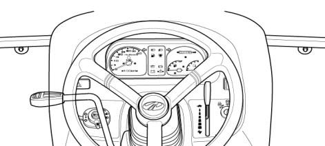
INSTRUMENT AND SWITCHES
► MAIN SWITCH (KEY SWITCH)
[OFF] -The key can be inserted or removed
[ON] -Theelectriccircuitison&preheatfunction
[START] -Thestartermotorisengaged.
WhenthekeyisreleaseditwillreturntotheONposition
[GLOW] -Glowplugspreheatthecombustionchamber
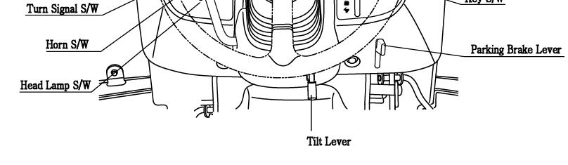
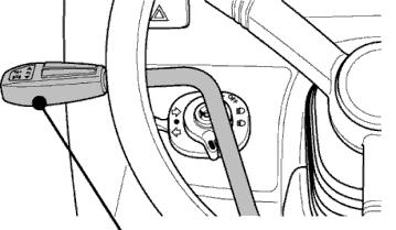
► HEADLAMP,TURNSIGNALSWITCHANDHORN
■ HEADLAMPSWITCH
Highandlowbeamareoperatedonthemainswitch
Position ①.Lowbeam
Position ②.Highbeam
■ TURNSIGNALSWITCH
Pulltheturnsignalleverdowntosignalaleftturn. Pushtheturnsignalleveruptosignalarightturn.
■ HORN
PushtheRedbutton.
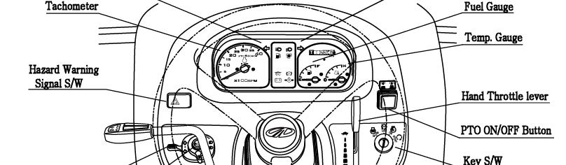
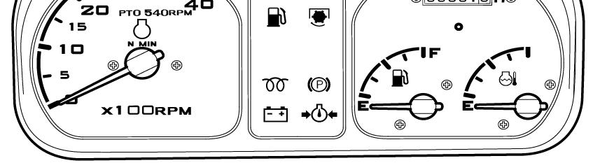
► HOURMETER
The hour meter consists of digits with the last digit indicating 1/10th of an hour.
Symbol Illuminates when the Hour meter is operated.
► TACHOMETER
Thismetershowstherevolutionsoftheengineandthe PTOshaftsaswellasthetravelspeedintopgear.
► FUELGAUGE
Shows the amount of fuel in the tank when the ignition switch is ON.
► WATER TEMPERATURE GAUGE
Showsthewatertemperaturewiththeignitionswitch ON C is low to normal temperature
H ishightemperature
If the pointer is in the red H segment the engine is overheating.
Refertothisbooktorectifytheproblem Refer to this book to rectify the problem
► HAZARD WARNING SIGNAL SWITCH
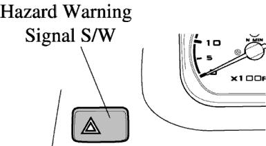
Push the hazard warning signal once to operate the hazard warning light. (Left and right turn indicators flash).
Push the hazard warning light switch again to switch off the hazard warning lights.
High beam lamp is operated on the combination switch.
Low beam lamp is operated on the combination switch
Parkingbrakeisoperatedwhenfootbrakeisengaged.
Parking brake is operated when footbrake is engaged.
PTO monitor Lamp Shows the revolution of PTO. Refer to monitor lamp on Page 39
Fuel Level
Ifitcomesonwhiletheengineisrunning,fillthetankwithfuel.
If it comes on while the engine is running, fill the tank with fuel.
Oilpressurelamp
Will go out as soon as the engine starts if the oil pressure is correct. If it comes on while the engine is running, stop the engine and get expert advice
Charge lamp
Thislightwillgooffassoonastheenginestartstoruntoindicatethatthealternatorischanging
This light will go off as soon as the engine starts to run to indicate that the alternator is changing (Please note, as a broken fan belt can cause the light to come on, please stop the engine as overheating can occur if not rectified immediately)
Glow signal Lamp indicates preheating
■ THE PTO MONITOR LAMP on the dash panel indicates the state of the PTO shaft.
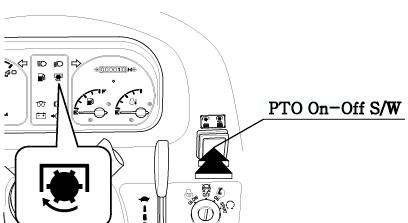
1.If the monitor glows: The PTO is rotating
2.If the monitor is off: The PTO is off
3 Ifthemonitorblinks:ThePTOispresentlystationarybutwill If the monitor blinks: The PTO is presently stationary but will instantly start rotating if the clutch pedal is released or the implements lowered.
Two switches operate the independent PTO.
1. PTO ON/OFF SWITCH: PTO ON/OFF switch is located on the RHS. on the steering column and can be identified easily with its built in red colored indicator. When the switch is pushed down to start the PTO indicator glows to indicate that the switch and the PTO are in ON position, If the switch is pushed down again the indicator goes off signaling that the PTO is OFF.
PTO monitor Lamp
Tractor Controls
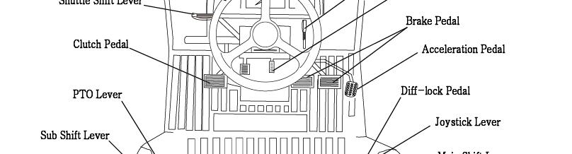
► THROTTLE LEVER (HAND THROTTLE)
Pullingthehandthrottletowardsthedriverincreaserevolutions Pulling the hand throttle towards the driver increase revolutions. Pushing it away from the driver decreases revolutions.
► CLUTCH PEDAL
When the clutch pedal is pressed on models with mechanical transmissions, drive is disengaged and gg the gear range and forward or reverse travel can be selected. When moving off, smoothly release the pedal to set the tractor moving.
► CLUTCH CUT-OFF ARM
For the long term storage of the Tractor it is possible to latch the clutch in the disengaged position. Push the clutch down and engage the latch to hold it there.
Do not attempt to start engine when this arm is being used. Warning
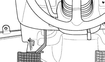
► BRAKEPEDAL
Right
BRAKE PEDAL Caution
A connecting latch is provided to connect the right and left brake pedals for high speed or road use.
Intheinterestofsafetyalwaysuseitontheroadorathighspeedasusingoneside onlycancauserollovers.
When servicing the tractor ensure that the adjustment on both sides is the same.
► FOOT OPERATED ACCELATOR
This pedal can override a fixed hand throttle setting
► PARKING BRAKE LEVER
Connectthebrakepedalspushthemdownwhile Connect the brake pedals , push them down while pulling the park brake up to engage. Press the parking brake pedal and push the Brake pedal to release.
Traveling with the parking brake on will damage the brakes. Important
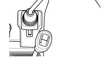
► SHUTTLE SHIFT LEVER
This control allows shifting from forward to reverse & reverse to forward. When stationary set the lever to N for neutral
① Push the lever away from the driver engages forward.
② Pullingthelevertowardsthedriverengagesreverse
Pulling the lever towards the driver engages reverse
1.Press the clutch pedal down completely before operating the shuttle shift lever.
Important
2.When changing from forward to reverse or back to forward again while in high range make sure the tractor comes to a stop before changing direction. Failure to do so is likely to result in damage to the mechanism and place the driver at risk of injury.
Caution py
Operate the shuttle shift only while seated on the tractor.
Do not use the shuttle shift lever to start the tractor for towing or traveling uphill, use the clutch instead.
Always stop the tractor before getting off.
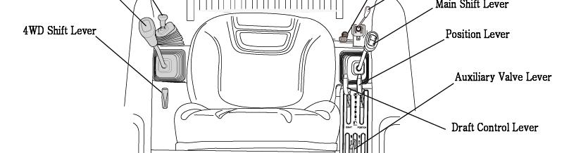
▶Main gear lever
This lever can be shifted by using the clutch, both when the tractor is stationary or mobile.
It is located on the RHS of the driver seat.
▶ Sub gear lever(Linear shift lever)
Operate the sub gear lever using the clutch to select the appropriate speed for different applications.
It is located on the LHS of driver seat.
Main gear lever Sub gear lever(Linear shift lever)
Avoid damage!
Select the proper speed range and gear for the job.
•The machine maybe operated in any gear with engine speeds at 950-2600 rpm. Within these limits, the engine can be placed under varying load operations.
Weses,eegecbepcedudevygodopeos.
Important
•Never overload engine by lugging machine at low idle speeds.
•Raise engine speed to match expected loads. If a slight increase in engine rpm occurs simultaneously with the moving of the hand throttle lever forward, the engine is not overloaded.
► The Main shift lever provides four speed positions. The Sub shift lever provides 3 ranges. The Shuttle shift lever controls travel direction. Use all three levers in different combinations to achieve 12 forward and 12 reverse speeds. Machine motion must stop and the clutch pedal must be depressed before changing ranges. Gear may be changed while machine is in motion if clutch pedal is completely depressed.
Do not operate gear levers without stopping the tractor & without using the clutch. Important
► TO AVOID PERSONAL INJURY:
○ Whenyouleavethetractor,besuretoapplytheparkingbrakeandstoptheengine
When you leave the tractor,be sure to apply the parking brake and stop the engine
○ In applying the brakes:
-The torque of wheel axle is extremely high while creep speed is being used.Be sure to step down on the clutch pedal completely before applying the brakes,or they will not work.
-When starting to operate the tractor,be sure to release the parking brakes.Misuse of the brakes may cause damage to the transmission and is therefore not acceptable to Mahindra for coverage under the warranty.
► DIFF-LOCK PEDAL
In the case of wheel slippage use the diff-lock by pushing down on the diff lock pedal. To release it remove the foot from the pedal.
Tractor will be difficult to turn if the Diff-lock is engaged, ensure the lock is disengaged before turning the steering wheel. Danger
Important
Do not use high engine RPM when engaging Diff lock If the diff lock does not release after removing the foot from the diff lock pedal, brake with the left and right brake alternatively, until it gets released.
Never use the diff lock at high speed or on the road as this can cause roll over and injury.
Caution
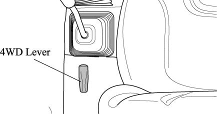
► FRONTWHEELDRIVELEVER FRONT WHEEL DRIVE LEVER
In the ON position the front wheels are engaged and in the OFF position they are disengaged. Engage & disengage the front wheel drive with the front wheels in the straight position and at low Engine RPM.
Do not use front wheel drive at high speed or on the road as premature wear of components will result. Important
Use of front wheel drive improves traction performance.
► DRIVER’S SEAT
To adjust the seat backwards and forwards lift the lever at the front of the seat and set it to the desired position
► TILT LEVER important
To adjust the inclination of the steering wheel with 3 stages and set it to the desired position.
Always use the clutch when using the front wheel drive lever.
Ensure that the tilt lever has locked before moving the tractor. Danger
Pto Gear Selection Lever
Your tractor is equipped with a 1Speed PTO to suit a range of applications and conditions.
POSITION
Model
1st
6110 Gear Cab540
Always use the clutch when engaging or disengaging the PTO or changing PTO speed. Let the PTO driven implement come to a complete stop before changing. Important Caution
Do not operate any implement at a higher speed than as specified. When making adjustments to the implement stop the engine to avoid serious injury. WhenleavingthetractorstoptheengineandremovethekeySettheparkingbrake When leaving the tractor, stop the engine, and remove the key Set the parking brake
OPERATING THE HYDRAULICS.
The hydraulics are powered with an engine driven hydraulic pump and controlled with a position control lever mounted beside the driver.
Positioncontrol Position Control
► Implements can be raised and lowered with the hydraulic position control lever and can be stopped at any position by stopping the lever.
To ensure a consistent working depth the adjustable stop can be set to ensure that the implement returns to the same depth every time.
To raise the implement: Pull the lever back To lower the implement: Push the lever forward.
Warning
After finishing the work, always lower the implement to the ground and switch off the engine, Set the parking brake to avoid injuries and accidents .
► DRAFT CONTROL LEVER
Soil engaging implements can be set for precision work by using draft control.
By mounting the lever forward. the depth increases & by moving the lever backwards the depth increases.
► LOWERING SPEED CONTROL KNOB FOR THE 3 POINT HITCH
This knob controls the downward speed of the Hydraulic’s three point linkage and is positioned at the front of the driver’s seat.
To slow the downward speed-Turn the knob clockwise.
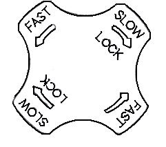
To increase the downward speed, turn the knob counterclockwise. To lock the knob, turn clockwise. Do not over tighten the knob.
Always set the knob to lock when
1.Traveling on the road
2.Replacing tires or blades on an implement.
3.Making adjustments to an implement. Sudden dropping of an implement due to hydraulic problems can cause serious injury or death. Caution
EXTERIOR HYDRAULIC LEVER
Move the lever up or down and hold. This will raise or lower the implement (rotavator or hydraulic plow). Detent type –Double-acting with Detent
Important:
-Do not hold the lever in the “pull” or “Push” position once the remote cylinder has reached the end of the stroke,. as this will cause oil to flow through the relief valve. Forcing oil through the relief valve for extended periods will overheat the oil.
-When Using the tractor hydraulic system to power front loader, do not operate the boom and bucket cylinders simultaneously.
► REMOTE HYDRAULIC CONTROL VALVE COUPLER CONNECTING AND DISCONNECTING.
■ Connecting
1.Clean both couplers.
2.Remove dust plugs.
3.Insert the implement coupler to the tractor hydraulic coupler
4.Pull the implement coupler slightly to make sure couplers are firmly connected.
■ Disconnecting
1.Lower the implement first to the ground to release hydraulic pressure in the hoses.
2.Clean the couplers.
3.Relieve pressure by moving hydraulic control levers with the engine shut off. Pull the hose straight from the hydraulic coupler to release it coupeoeese.
4.Clean oil and dust from the coupler, then replace the dust plugs.
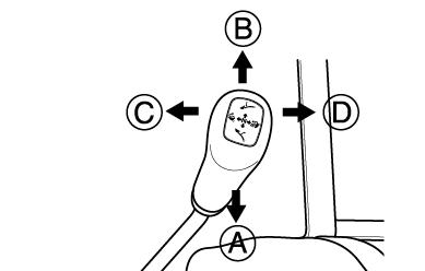
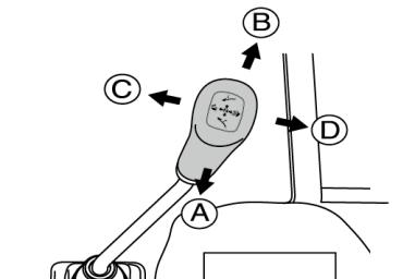
► JOYSTICKLEVER pp
This simple joystick lever can control the use of a front-end loader. And lift-retract, dump-rollback smoothly and act as one handle lever.
To raise the front end loader : pull the lever to lift position.
To lower the front end loader : push the lever to retract position.
To rollback the bucket : pull the stick to rollback position.
To dump the bucket : push the stick to dump position.
To raise the Boon of Front end loader .
To lower the Boon Front end loader.
To rollback the bucket.
To dump the bucket
NOTE : The Joystick control and valve can also be used for other applications if a front end loader is ypp not fitted.
► SAFETYIMPLEMENTFORJOYSTICKLEVER
This simple Safety locking system can lock the joy stick by pushing the Button and unlock it by pulling .
Warning
Hydraulic fluid escaping under pressure can have enough force to penetrate the skin. Hydraulic fluid may also infect a minor cut or opening in the skin. If injured by escaping fluid,. see a doctor at once. Serious infection or reaction can result if pg, medical treatment is not given immediately. Make sure all connections are tight and that hoses and lines are in good condition before applying pressure to the system. Release all pressure before disconnecting the lines or performing other work on the hydraulic system. To find a leak under pressure use a small piece of cardboard or wood. Never use hands.
► TELESCOPIC STABILIZERS ADJUSTMENT
The stabilizers are intended for limiting or preventing implement side movement.
There should be no clearance (Position A) during implement transport and when working with grades, rollers mowers, seeders, drills and similar implements. However, a slight play is necessary (Position B) when working with ploughs, harrows, ditchers, cultivators and the like: As when working with “draft control”.
The length of stabilizers is adjusted by removing the pin and rotating the turn buckle barrel by which the threaded ends are interconnected.
► ADJUSTMENT OF THE TOP LINK
Lengthening or shortening the top link will change the angle of the implement.
The locating hole of the top link varies with the type of implement used.
The most common locations are the 1st and 2nd hole from the top.
1) For general implement :Use the Pin to “A”point
2) For Draft control :Use the Pin to “B”point
► ADJUSTMENT OF LOWER LINK
The adjustment is done with the adjusting handle on the Right hand Lift rod.
To shorten it, wind the handle clockwise and to lengthen it wind it counter clockwise.
When adjusted correctly hold the turn buckle with the tidd stopper provided.
► LOWER LINK (IF EQUIPPED EXTENDABLE TYPE)
Push the point area and pull the end of the lower link to adjust the length of lower link.
► ADJUSTMENT OF THE LIFT LINK ON THE LOWER LINK
For different applications change the position of the lift rod on the lower links as shown and insert the pin in the direction of the arrow.
Only use drawbar to tow and keep the 3 point linkage in raised position when towing with the drawbar. Position can create unbalance causing the Tractor to roll-over & Result in death or serious injury. Danger
► MOUNTINGIMPLEMENT MOUNTING IMPLEMENT
If the PTO is used, remove the safety cover off the PTO shaft. Adjust the yoke rod on the lower links to suit the implement in use.
Attach the left lower link, then attach the right lower link using the adjusting handle on the leveling box if required. Attach the top link.
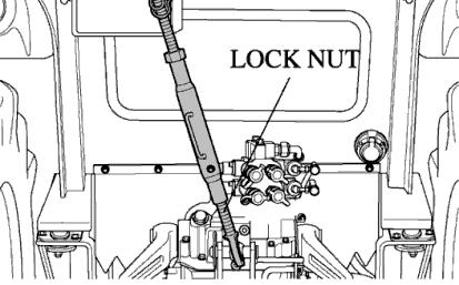
AtththPTOhfttthttifdkithtit Attach the PTO shaft to the tractor if used, making sure that it is locked in place. Adjust the check chains to suit the implement and tighten the locknuts.
To remove an implement reverses the procedure
Do not attach a PTO shaft while the engine is running and ensure all safety shields are in place.
Caution
Driving The Tractor
Starting The Engine
Before starting the engine carry out the pre-operational checks as set out on page 23.
(1) Sitonthedriverseat Sit on the driver seat
(2)Apply the footbrake.
(3)Put the hydraulic lever in the down position.
(4) Push down the clutch to activate the safety-starting switch.
(5)Put the main gear lever in neutral.
(6) Insert the ignition key and turn it on.
(7)Ensure that the warning lights are working.
(8) Operators need to turn key to the “ON” position. The glow circuit automatically activates. Otdtitfllihtttff
Operators need to wait for glow light to turn off As the lamp goes off turn the key to the start position to start the engine.
(9) Ensure that all the warning lights are off with the engine running.
Never turn the key to the start position while the engine is running as this can cause serious damage to the starter and engine flywheel. Only engage the starter for a period of not more than 10 seconds.
Important
If Engine does not start, rest the starter for about 20 seconds and try again for a maximum of 10 seconds.If the engine does not start after repeated attempts, refer to the fault tracing guide.
Especially in cold weather, always allow the tractor to idle for a while to warm up & build up sufficient oil pressure to ensure normal operating temperature for longer engine life. Important
Stopping The Engine
After long or heavy work allow the engine to idle for 5-10 minutes and turn the key off. Important
Warming Up
When starting the engine allow it to warm up to operating temperature by allowing it to idle 5-10 minutes to ensure full lubrication and operating temperature. Failure to do so can shorten engine life substantially.
►
Warming Up In Cold Weather
Cold weather will change the viscosity of the oil, resulting in a reduced oil pumping capacity, which can cause damage to the engine if it is not warmed up correctly. It also causes problems with the hydraulic system and the synchromesh in the transmission.
Correct times for warming up are:
TemperatureTime for warming up
Above 50°F 5~10 min.
50°F~32°F 10~20 min.
32°F~14°F 20~30 min.
14°F~-4°F 30~40 min.
Below –4°F Over 40 min.
Ensure the handbrake (Foot brake) is on during the warming period. Failure to warm up correctly can result in problems.
Important
When the engine is warm, push down the clutch and engage the main and auxiliary gear levers to the required position. Push down on the brake pedals and release the handbrake. Increase the engine revolutions and let out the clutch smoothly.
Only change gears with the main gear lever while moving and ensure that this is done with the full use of the clutch.
► STORINGENGINEINOPERABLECONDITIONFOR3MONTHSORMORE
Storing Engine In Operable Condition For 3 Months Or More
When the engine is not operated during a storage period of three months or more, internal engine parts can rust and lose oil film. As a result, the engine can seize when it is started after storage. To prevent such a rust, the engine must be operated periodically during storage.
Caution
Do not ”ride” the clutch to control speed, use a lower gear. Do not travel with your foot on the clutch pedal.
Danger esobseveocegsododues.
Always connect the brake pedals when traveling on the road. Never tow anything except with the drawbar. Do not tow loads which are too large for the tractor’s capacity to brake effectively especially in hilly terrain. Take special care when towing large or wide implements. Do not carry passengers. At all times observe local legislation and road rules.
TIGHT TURNS IN THE FIELD
Disconnect the latch connecting the left and right brake pedals to allow the use of individual pedals.
To make a tight turn use both the steering wheel and the brake pedal at the same time.
Foraleftturnusetheleftpedalandarightturntherightpedal. For a left turn use the left pedal and a right turn the right pedal.
Perform tight turns only at a slow safe speed. Doing so at a high speed can cause rollovers and very serious injury or death.
Caution
NORMALBRAKINGANDPARKING NORMAL BRAKING AND PARKING
Let the engine come back to idle and at the same time push in the clutch and brake simultaneously.
When the tractor has come to a halt, lower any implement to the ground, and put the main gear in neutral. Apply the parking brake, stop the engine, and remove the key.
Illustration
Caution
Always apply the parking brake when parking. Failure to do so can cause accidents and damage. As an extra precaution when parking on a slope, chock the rear wheels.
Uphill Starts On A Steep Slope
With the pedals connected together push down on the brake pedals and push down the clutch.
Set all gear levers to low and the throttle to medium engine speed. Release the clutch and as it engages release the brake pedals.
► DRIVING DOWNHILL
Use the engine’s ability to brake when traveling downhill. Never rely on the brakes only and never travel downhill with the gears in neutral.
Adjust the throttle to the required speed. please drive with extra care
When operating in hilly terrain the risk of the rollover is increased substantially, pleasedrivewithextracare
When towing trailers in hilly terrain ensure that they are equipped with brakes, use a lower gear to get maximum engine braking and do not change gears on a down hill run
Operation Of The Diff Lock
While the diff lock is a very useful feature, care should be taken in its use as misuse can lead to dangerous situations.
The diff lock should only be used in situations where traction is lost on one of the rear wheels.
Use low engine revolutions when using the diff lock.
Warning
If the diff lock does not release after removing the foot from the pedal use the left and right brake pedals in turn to release it. Do not try to engage or use the diff lock on tight turns as serious damage can result.
Check During Driving
Constantly monitor the warning lights on the dash and if any come on, stop the tractor to determine the cause. If the oil pressure light comes on, check the oil level first of all. If the oil level is OK, ask a qualified dealer to check the reasonforthelightcomingon reason for the light coming on
If the alternator warning light comes on, check all connections and ensure that the fan belt is not broken.
If all connections and the fan belt are intact, consult your dealer to determine the cause of the problem.
► FUEL GAUGE.
Toavoid excessive condensation in the fuel tank, refill at the end of each day’s work and ensure during the day that it does not drop to a low level where the fuel system will require bleeding to expel air in the system after refillingthetank refilling the tank
► ENGINE COOLING WATER.
If the gauge indicates that the engine is running hot, stop the tractor and check the coolant in the radiator.
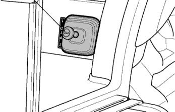
► TRAILER SOCKET (Seven Terminal Electrical Socket type)
To operate the Electrical system of implements, trailer lighting, warning lamp etc.
Danger
Allow the engine to cool down before opening the radiator as serious burns may result due to hot steam & boiling water.
Also check to ensure that the fins in the radiator core are not clogged or that the tractor has a broken or stretched fan belt.
Caution
When traveling on public or farm roads connect both brake pedals and allow for the weight of any mounted implement to ensure that the unit is not unbalanced. Also allow for the width when passing other road users. Where fitted, use the hazard lights provided. Strictly follow the local traffic regulations.
When operating near others with an implement attached take particular care to allow for the width of the implement and avoid accidents.
►
Track Adjustment
As 6110 Gear models of Mahindra are front wheel assist, the front track can be set in The rear track can be set in as illustrated.
6110 Gear
Typedivisiontyretread
AG
IND
FRONT9.5-20 Hi Trac Lug1546(60.9)
REAR14.9-28 Hi Trac Lug1403(55.2)
FRONT10.5-80-18 Contractor1605(63.2)
REAR18.4-24 Industrial Tractor1384(54.5)
Unit : mm(in) Tread