17 minute read
UNIVERSAL SYMBOLS


Some of the universal symbols have been shown below with an indication of their meaning
Engine speed rev/minX100)
Pressuredopen slowly
Corrosive substance
Hours, recorded Continuous variable
Engine coolant temperature
Warning
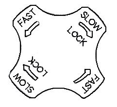
”Tortoise” Slow or minimum Setting
”Hare” fast or maximum setting
Fuel level Hazard warning
Transmission oil pressure
Engine Stop control Neutral Turn signal Lights
Fan
Transmission oil temperature
Section -A Controls, Instruments And Operations
The following pages in this section detail the location and function of various instruments, switches and controls on your Tractor. Even if you operate otherTractors, you should read through this section of the manual and ensure that you are thoroughly familiar with the location and function of all the features of your New Tractor.
Do not start the engine or attempt to drive or operate the Tractor until you are fully accustomed to all the controls. It is too late to learn once the Tractor is moving. If in doubt about any aspect of the operation of the tractor consult your Mahindra Tractor Dealer/Distributor.
Particular attention should be paid to the recommendations for running-in to ensure that your tractor will give long life and dependable service for which it was intended.
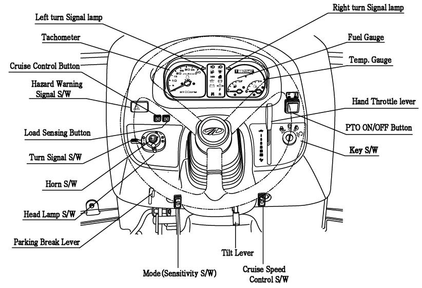
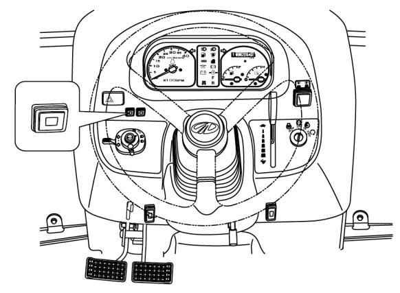
Description Of Tractor Controls
Instrument And Switches
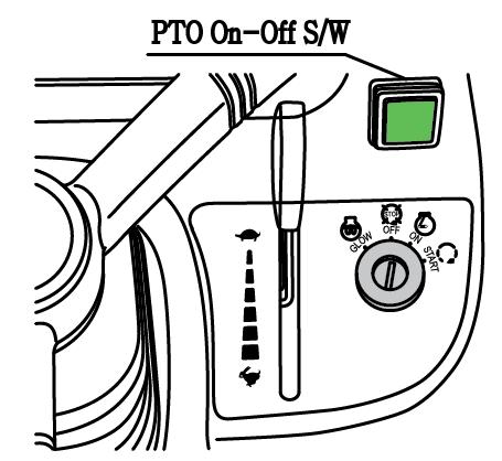
► MAIN SWITCH (KEY SWITCH)
[OFF] -The key can be inserted or removed
[ON] -The electric circuit is on & preheat function
[START] -The starter motor is engaged.
When the key is released it will return tothe ON position
[GLOW] -Glow plugs preheat the combustion chamber
► HEAD LAMP, TURN SIGNAL SWITCH AND HORN

■ HEAD LAMP SWITCH
High and low beam are operated On the main switch
Position ①. Low beam
Position ②. High beam
■ TURN SIGNAL SWITCH
Pull the turn signal lever down to signal a left turn.
Push the turn signal lever up to signal a right turn.
■ HORN
Push the Red button.
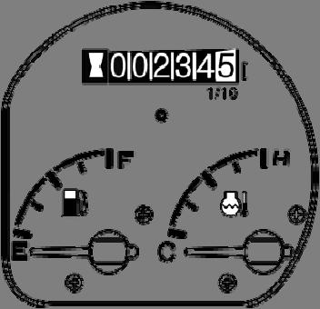
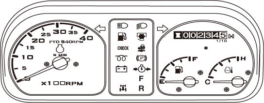
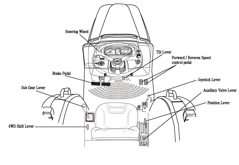
► HOUR METER
The hour meter consists of digits with the last digit indicating 1/10th of an hour. It shows hours the tractor has been used.
The lamp at bottom of hour meter should twinkle during Operation.
► TACHOMETER
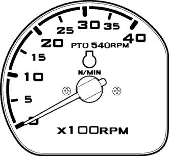
This meter shows the revolutions of the engine and the PTO shafts as well as the travel speed in top gear.
►FUEL GAUGE
Shows the amount of fuel in the tank when the ignition switch is ON
►WATER TEMPERATURE GAUGE
Shows the water temperature with the ignition switch ON C is low to normal temperature
H is high temperature
If the pointer is in the red H segment the engine is overheating. Refer this book to rectify the problem
► HAZARD WARNING SIGNAL SWITCH
Push the hazard warning signal once to operate the hazard warning light. (Left and right turn indicators flash). Push the hazard warning light switch again to switch off the hazard warning lights.
High beam lamp is operated on the combination switch
Low beam lamp is operated on the combination switch
Parking brake lamp is operated on when the ignition key is turned onto “ON”with the hand brake engaged.
PTO monitor Lamp Will turn on when PTO clutch is engaged
Fuel Level indicator lamp. If it comes on while the engine is running, Fill the tank with fuel.
Engine oil pressure lamp will go out as soon as the engine starts if the oil pressure is correct.
If it comes on while the engine is running, stop the engine and get expert advice.
Charge lamp
This light will go off as soon as the engine starts to run to indicate that the alternator is changing.
(Please note, as broken fan belt can cause the light to come on,please stop the engine as overheating can occur if not rectified immediately)
Glow signal Lamp is operated on when the ignition key is turned onto “GLOW”or “ON”for preheating
Cruise Control Lamp
Will turn on when cruise control is engaged
Forward indicator lamp is operated when F/R Lever indicated forward ,Reverse indicator lamp is operated when F/R Lever indicated reverse
Check Lamp
Will turn on when the key switch is set to ON position and safety start conditions are not satisfied. Safety start conditions : ① Brake pedal is depressed ② PTO ON/OFF switch is OFF If it comes on when safety start conditions are satisfied, some electric part is in trouble.
Load Sensing Lamp
Will turn on when load sensing function is activated.
■ THE PTO MONITOR LAMP on the dash panel indicates the state of the PTO shaft.
1.If the monitor glows: The PTO is rotating
2.If the monitor is off: The PTO is off
3.If the monitor blinks: The PTO is presently stationary but will instantly start rotating of the clutch pedal is released or the implements lowered.
Two switches operate the independent PTO.
1.PTO ON/OFF SWITCH: PTO ON/OFF switch is located on the RHS. on the dash cover and can be identified easily with its built in red colored indicator. When the switch is pushed down to start the PTO indicator glowsto indicate that the switch and the PTO are in ON position, If the switch is pushed down again the indicator goes off signaling that the PTO is OFF.
Warning
If working on hard soils,pavements with a rotary implement the PTO ON/OFF switch must be put to the OFF position to stop the PTO from rotating , If this is not done the rotating blades of the implement will push on the hard ground below and in turn push the tractor toward causing accident which can lead to serious injuries or death.
2. Extra precaution must be taken to clear the area of bystanders/onlookers when using PTO driven implements. The rotating blades of the implements can cause serious injuries on contact. The warning that is indicated by the blinking PTO monitor is to make the operator aware that the PTO is in on position and will instantly start rotating if the clutch pedal is released or implement is lowered or both.
3.In no case the specified rotating speeds indicated by the implement manufacturer be crossed as the same can lead to serious damage to the tractor/equipment and canlead to serious injuries to persons around.
► CRUISE CONTROL BUTTON
■ Engaging Cruise Control
–Depress the forward speed control pedal until the required speed is achieved.
–Press the cruise control button to engage cruise control.
–Release the forward speed control pedal.
–The cruise control is only operational when the machine is traveling forward.
■ Disengaging Cruise Control
To disengage the cruise control you can either press the cruise control button or depress the brake pedal.
► CRUISE SPEED CONTROL SWITCH
Cruise speed can be increased or decreased while cruise control is engaged.

Press and release top of cruise speed control switch(+) to increase cruise speed by increment ratio. Press and release again to increase cruise speed more by increment ratio.
Press and release bottom of cruise speed control switch(-) to increase by increment ratio. Press and release again to decrease cruise speed more by increment. ratio
Adjusted setting is erased when cruise control is disengaged.
►LOAD SENSING BUTTON
Load sensing function is used to prevent engine from stalling during heavy load application. Press load sensing button to activate load sensing function.
If the engine speed drops more than the set range, the controller reduce HST speed to help the engine to recover. The heavier load on the engine, the tractor speed is more and more reduced.
Press again the switch off the load sensing function.
► MODE(SENSITIVITY) SWITCH
The tractor allows the user to choose a response sensitivity among three different modes.
■ Mode 1
Fully depress top of mode switch to activate mode 1. This mode gives the higher response sensitivity to drive pedal movement. It will provide more quick changes in speed or direction. The tractor would be more jerky.

■ Mode 2
Depress top or bottom of mode switch to activate mode 2. This mode gives the medium response sensitivity to drive pedal movement which is typical to most normal operating conditions.
■ Mode 3
Fully depress bottom of mode switch to activate mode 3. This mode gives the slow response sensitivity to drive pedal movement.
Tractor Controls
► THROTTLE LEVER ( HAND THROTTLE )
Pulling the hand throttle towards the driver increase engine speed.
Pushing it away from the driver decreases engine speed.
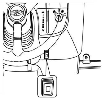
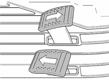
► SPEED CONTROL PEDAL
The Speed Control Pedal is located in RHS of the Operator floor.
Depress the forward speed control pedal to move forward. Depress the reverse speed control pedal to move backward. The speed control pedal will return in neutral position and the tractor will stop when the speed control pedal is released.
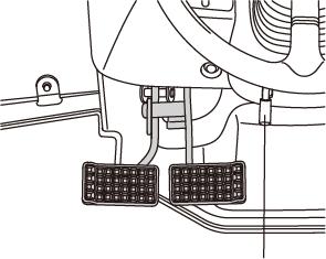
► BRAKE PEDAL
Caution
A connecting latch is provided to connect the right and left brake pedals for high speed or road use.
In the interest of safety always use it on the road or at high speed as using one side only can cause rollovers.
When servicing the tractor ensure that the adjustment on both sides in the same.
► PARKING BRAKE LEVER
Connect the brake pedals, push them down while pulling the park brake lever up to engage. Push the Brake pedal to release.
Traveling with the parking brake on will damage the brakes. important
► TO AVOID PERSONAL INJURY:
○ When you leave the tractor, be sure to apply the parking brake and stop the engine.
○ In applying the brakes:
The torque of wheel axle is extremely high while creep speed is being used. Be sure to step down on the clutch pedal completely before applying the brakes, or they will not work. When starting to operate the tractor, be sure to release the parking brakes. Misuse of the brakes may cause damage to the transmission and is therefore not acceptable to Mahindra for coverage under the warranty.
► SUB GEAR LEVER (RANGE SHIFT LEVER)
Operate the sub gear lever using clutch to select the appropriate speed for different applications.
It is located on the LHS of driver seat.
important
Avoid damage! To prevent transmission damage:
1.Depress clutch pedal and stop machine motion completely beforeshifting the main shift & reverselever (changing direction forward and reverse ).
2.While operating machine, always depress clutch pedal and stop machine motion before changing travel gears.
3.Never rest a foot on the clutch pedal while machine is in motion.


► DIFF-LOCK PEDAL
In case of wheel slippage use the diff-lock by pushing down on the diff lock pedal.
To release it remove the foot from the pedal.
Tractor will be difficult to turn if the Diff-lock is engaged, ensure the lock is disengaged before turning the steering wheel. Danger
Tractor will be difficult to turn if the Diff-lock is engaged, ensure the lock is disengaged before turning the steering wheel. Danger
Do not use high engine RPM when engaging Diff lock If the diff lock does not release after removing the foot from the diff lock pedal alternatively brake with the left and right brake until it gets released. important
Caution
Never use the diff lock at high speed or on the road as this cancause roll over and injury.
► FRONT WHEEL DRIVE LEVER (4WD)
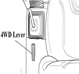
In the ON position the front wheels are engaged and in the OFF position they are disengaged.
Engage & disengage the front wheel drive with the front wheels in the straight position and at low Engine RPM.
Do not use front wheel drive at high speed or on the road as premature wear of components will result. important
Always use the clutch when using the front wheel drive lever. important
Use of front wheel drive improves traction performance.
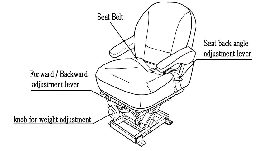
► DRIVER’S SEAT
To adjust the seat backwards and forwards push left side the lever at the front of the seat and set it to the desired position
► TILT LEVER
To adjust the inclination of the steering wheel with a 3 stages and set it to the desired position.
Danger
Pto Gear
Your tractor is equipped with 1 Speed rear PTO to suit range of applications and conditions. Use the PTO switch to engage or disengage rear PTO.
MODELSPEED (rpm)
6010 HST Cab540
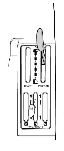
OPERATING THE HYDRAULICS.
The hydraulics are powered with an engine driven hydraulic pump and controlled with a position control lever mounted beside the driver.
Position Control
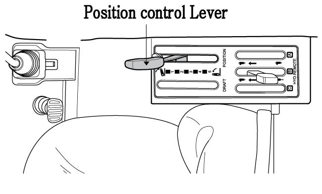
► Implements can be raised and lowered with the hydraulic position control lever and can be stopped at any position by stopping the lever.
To ensure a consistent working depth the adjustable stop canbe set to ensure that the implement returns to the same depth every time.
To raise the implement: Pull the lever back
To lower the implement: Push the lever forward.
After finishing the work, always lower the implement to the ground and switch off the engine, Set the parking brake to avoid injuries and accidents . Warning
► LOWERING SPEED CONTROL KNOB FOR THE 3 POINT HITCH
This knob controls the downward speed of the hydraulics three point linkage and positioned at the front of the driver’s seat.
To slow the downward speed-Turn the knob clockwise. To increase the downward speed, turn the knob anticlockwise.
To lock the knob clockwise. Do not over tighten the knob.
Caution
Always set the knob to lock when
1.Traveling on the road
2.Replacing tires or blades on an implement.
3.Making adjustments to an implement. Sudden dropping of an implement due to hydraulic problems can cause serious injury or death.
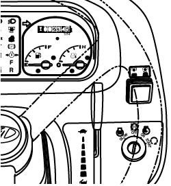
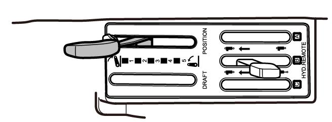
Remote Hydraulic Valve Lever
Move the lever up or down and hold. This will raise or lower the implement (rotavator or hydraulic plow). Remote control valve is detent type (double-acting with Detent).
Important:
Do not hold the lever in the “pull”or “Push”position once the remote cylinder has reached the end of the stroke. As this will cause oil to flow through the relief valve. Forcing oil through the relief valve for extended periods will overheat the oil.
When Using the tractor hydraulic system to power front loader, do not operate the boom and bucket cylinders simultaneously.

► REMOTE HYDRAULIC CONTROL VALVE COUPLER CONNECTING AND DISCONNECTING.
■ Connecting
1.Clean both couplers.
2.Remove dust plugs.
3.Insert the implement coupler to the tractor hydraulic coupler
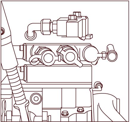

4.Pull the implement coupler slightly to make sure couplers are firmly connected.
■ Disconnecting
1.Lower the implement first to the ground to release hydraulic pressure in the hoses.
2.Clean the couplers
3.Relieve pressure by moving hydraulic control levers with engine shut off. Pull the hose straight from the hydraulic coupler to release it
4.Clean oil and dust from the coupler,then replace the dust plugs.
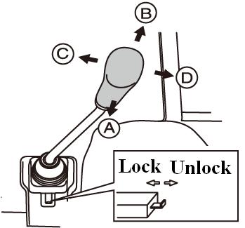
► JOY STICK LEVER
This simple joystick lever can control the use of a front-end loader. And lift-retract, dump-rollback smoothly and act as one handle lever.
To raise the front end loader : pull the lever to lift position.
To lower the front end loader : push the lever to retract position.
To rollback the bucket : pull the stick to rollback position.
To dump the bucket : push the stick to dump position.
To raise the front end loader.
To lower the front end loader.
To rollback the boom
To dump the boom
► SAFETY IMPLEMENT FOR JOYSTICK LEVER
This simple Safety locking system can lock the joystick by pushing the Button and unlocked by pulling .
NOTE : The Joystick control and valve can also be used for other applications if a front end loader is not fitted.
Warning
Hydraulic fluid escaping under pressure can have enough force topenetrate the skin.
Hydraulic fluid may also infect a minor cut or opening in the skin.
If injured by escaping fluid. See a doctor at once.
Serious infection or reaction can result if medical treatment is not given immediately. Make sure all connections are tight and that hoses and lines arein good condition before applying pressure to the system.
Release all pressure before disconnecting the lines or performing other work on the hydraulic system.
To find a leak under pressure use a small piece of cardboard or wood. Never use hands.

OPERATING THE 3 POINT LINKAGE (TPL)
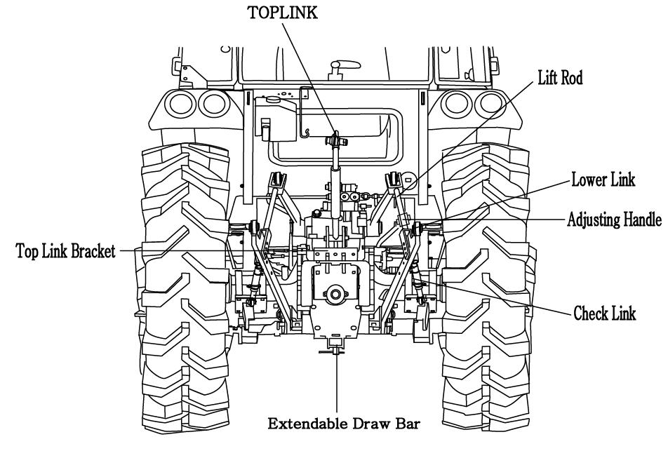
► ADJUSTMENT OF THE CHECK CHAIN
There should be no clearance during implement transport and when working with grades, rollers mowers, seeders, drills and similar implements. However, a slight play is necessary when working with ploughs,harrows, ditchers, cultivators.
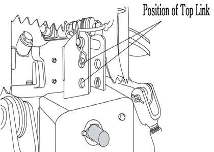
► ADJUSTMENT OF THE TOP LINK
Lengthening or shortening the top link will change the angle of the implement.
The locating hole of the top link varies with the type of implement used.
The most common locations are the 1st and 2nd hole from the top.
► ADJUSTMENT OF THE LIFT ROD
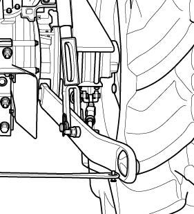
The adjustment is done with the adjusting handle on the Right hand Lift rod.
To shorten it wind the handle clockwise and to lengthen it wind it counter clockwise.
When adjusted correctly hold the turn buckle with the stopper provided.
► ADJUSTMENT OF THE LIFT ROD ON THE LOWER LINK
For different applications change the position of the lift rod on the lower links as shown and insert the pin in the direction of the arrow.
Lift Rod insert the Pin
Check Chain insert the Pin
Only use drawbar to tow and keep the 3 point linkage in raised position when towing with the drawbar.
Position can create unbalance causing the Tractor to roll-over & Result the death or serious injury. Danger
► MOUNTING IMPLEMENT
If the PTO is used, remove the safety cover off the PTO shaft. Adjust the yoke rod on the lower links to suit the implement in use.
Attach the left lower link, then attach the right lower link using the adjusting handle on the leveling box if required. Attach the top link.
Attach the PTO shaft to the tractor if used, making sure that it is locked in place. Adjust the check chains to suit the implement and tighten the locknuts.
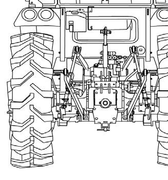
To remove an implement reverses the procedure
Do not attach a PTO shaft while the engine is running and ensureall safety shields are in place.
Caution
Driving The Tractor Starting The Engine
Before starting the engine carry out the pre-operational checks as set out on page 24.
(1)Sit on the driver seat
(2)Apply the footbrake.
(3)Put the hydraulic lever in the down position.
(4) Push down the clutch to activate the safety-starting switch.

(5)Put the main gear lever in neutral
(6) Insert the ignition key and turn it on
(7)Ensure that the warning lights are working
(8) Operator need to turn key to the “ON”position. The glow circuit automatically activates. Operator need to wait for glow light to turn off .As the lamp goes off turn the key to the start position to start the engine.
(9) Ensure that all the warning lights are off with the engine running.
Important
Never turn the key to the start position while the engine is running as this can cause serious damage to the starter and engine flywheel.
Only engage the starter for a period of not more than 10 seconds.
If Engine does not start, rest the starter for about 20 seconds and try again for a maximum of 10 seconds.
If the engine does not start after repeated attempts ,refer to the fault tracing guide.
Especially in cold weather, always allow the tractor to idle fora while to warm up & build up sufficient oil pressure to ensure normal operating temperature for longer engine life. Important
Stopping The Engine
-After light work let the engine idle for a while and turn the key off.
Important
After long or heavy work allow the engine to idle for 5-10 minutes and turn the key off.
Warming Up
When starting the engine allow it to warm up to operating temperature by allowing it to idle 5-10 minutes to ensure full lubrication and operating temperature. Failure to do so can shorten engine life substantially.
► WARMING UP IN COLD WEATHER
Cold weather will change the viscosity of the oil, resulting in a reduced oil pumping capacity, which can cause damage to the engine if it is not warmed up correctly.It also causes problems with the hydraulic system and the synchromesh in the transmission.
Correct times for warming up are:
Temperature
Time for warming up
Above 50°F 5~10 min.
50°F~32°F 10~20 min.
32°F~14°F 20~30 min.
14°F~-4°F 30~40 min.
Below –4°F Over 40 min.
Important
Ensure the handbrake (Foot brake) is on during the warming period. Failure to warm up correctly can result in problems.
When the engine is warm push down the clutch and engage the mainand auxiliary gear levers to the required position.
Push down on the brake pedals and release the handbrake. Increase the engine revolutions and let out the clutch smoothly. Only change gears with main gear lever while moving and ensure that this is done with fully use of the clutch.
► STORING ENGINE IN OPERABLE CONDITION FOR 3 MONTHS OR MORE
When the engine is not operated during storage of three months or more, internal engine parts can rust and lose oil film.
As a result, the engine can seize when it is started after storage. To prevent such a rust, the engine must be operated periodicallyduring storage.
Danger
Always connect the brake pedals when traveling on the road. Never tow anything except with the drawbar. Do not tow loads which are too large for the tractor’s capacity to brake effectively especially in hilly terrain. Take special care when towing large or wide implements. Do not carry passengers.
At all times observe local legislation and road rules.
Tight Turns In The Field
Disconnect the latch connecting left and right brake pedals to allow the use of individual pedals.
To make a tight turn use both the steering wheel and the brake pedal at the same time.
For a left turns use the left pedal and a right turn the right pedal.
Caution
Perform tight turns only at a slow safe speed. Doing so at a high speed can cause rollovers and very serious injury or death.
Normal Braking And Parking
Let the engine come back to idle and at the same time push in the clutch and brake simultaneously.
When the tractor has come to a halt, lower any implement to the ground, and put the main gear in neutral. Apply the park brake, stop the engine, and remove the key.
Illustration
Caution
Always apply the park brake when parking. Failure to do so can cause accidents and damage. As an extra precaution when parking on a slope, chock the rear wheels.
Uphill Starts On A Steep Slope
With the pedals connected together push down on the brake pedalsand push down the clutch.
Set all gear levers to low and the throttle to medium engine speed. Release the clutch and as it engages release the brake pedals. Adjust the throttle to the required speed.
► DRIVING DOWNHILL
Use the engine’s ability to brake when traveling downhill. Never rely on the brakes only and never travel downhill with thegears in neutral.
When operating in hilly terrain the risk of the rollover is increased substantially, please drive with extra care.
When towing trailers in hilly terrain ensure that they are equipped with brakes, use a lower gear to get maximum engine braking and do not change gearson a down hill run
Caution OPERATION OF THE DIFF LOCK
While the diff lock is a very useful feature, care should be taken in its use as misuse can lead to dangerous situations.
The diff lock would only be used in situations where traction islost on one of the rear wheels.
Use low engine revolutions when using the diff lock.
If the diff lock does not release after removing the foot from the pedal use the left and right brake pedals in turn to release it.
Warning
Do not try to engage or use the diff lock on tight turns as serious damage can result.
Check During Driving
Constantly monitor the warning lights on the dash and if any comes on stop the tractor to determine the cause. If the oil pressure light comes on check the oil level first of all. If the oil level is OK ask a qualified dealer to check the reason for the light coming on.
If the alternator warning light comes on check all connections and ensure that the fan belt is not broken.
If all connections and the fan belt are intact consult your dealer to determine the cause of the problem.
► FUEL GAUGE.
Toavoid excessive condensation in the fuel tank refill at the endof each day’s work and ensure during the day that it does not drop to a low level where the fuel system will require bleeding to expel air in the system after refilling the tank.
► ENGINE COOLING WATER.
If the gauge indicates that the engine is running hot, stop the tractor and check the coolant in the radiator.
► TRAILER SOCKET (Seven Terminal Electrical Socket type)
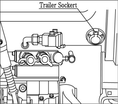
To operate the Electrical systems of implements, trailer lighting, warning lamp etc.
Allow the engine to cool down before opening radiator cap as serious burns may result due to hot steam & boiling water. Danger
Also check to ensure that the fins in the radiator core are not clogged or that the tractor has a broken or stretched fan belt.
Caution
When traveling on public or farm roads connect both brake pedalsand allow for the weight of any mounted implement to ensure that the unit is not unbalanced. Also allow for the width when passing other road users. Where fitted use the hazard lights provided.
Strictly follow the local traffic regulations.
When operating near others with an implement attached take particular care to allow for the width of the implement and avoid accidents.
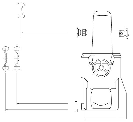
Caution
► TRACK ADJUSTMENT
As 6010HST Cab models of Mahindra are front wheel assist the front track can beset in The rear track can be set in as illustrated.
(*) Marking is STANDARD