14 minute read
3. Safety Precaution for Fly-Jib Operation


WARNING
・fly-jib kit under operation should be fixed by four bolts and three fix pins. Prior to start operation, always assure that all of three pins are set in positions correctly, as well as that four sets of bolts and nuts are driven tightly. In addition, ensure that snap retainers are correctly inserted to three fix pins to prevent them missing.
・When stowed, fly-jib is fitted to main-boom with two stowage pins. Prior to let the crane body travel, make sure that two pins are properly secured. Also, ensure that snap retainers are correctly inserted to these two pins to prevent them missing.
・Always check correct function of over hoist detector before starting fly-jib operation.
・Always fully extend two stages of Fly-Jib in use, because moment limiter's fly-jib mode calculates and indicates working radius and lifting height on basis of full length.
・Always make outriggers contact to the ground for fly-jib operation. (Outriggers position may be minimum extended.)
・Never pick and carry by fly-jib. It is a hazardous operation.
4. Instruction for Fly-Jib operation
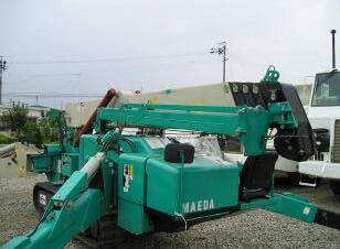
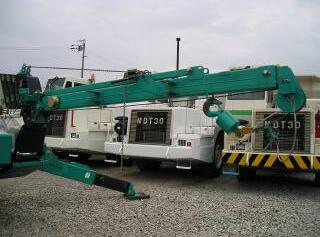
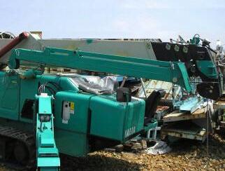
4.1 Fly-jib Installation Note : The picture shown is a prototype, and some detailed parts differ from mass-produced units. Procedure below specifies a condition that hoist wire is already attached to single fall hook and fitted to fly-jib kit. The procedure to change to single fall hook from main-boom hook block is specified in the next section.
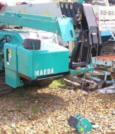
1) Place the crane on solid and level ground.
2) Retract main-boom to the minimum length and lower to the limit.
3) Extend outriggers and switch to crane mode then switch moment limiter to fly-jib mode, as well.
(Refer to "5. Instruction for Moment Limiter" for details.)
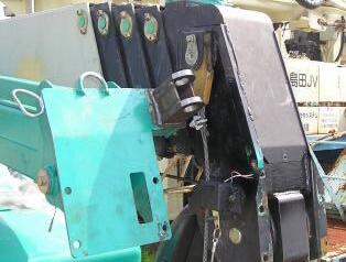
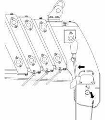
4) Hoist down hook so that the hoist wire is slacked, then remove stowage sheave from main-boom, which is fastened with one M12 bolt.
5) Set the accessory, lever block as indicated by ※ mark to adjust fly-jib kit to parallel so that rotary bracket pin is easily removed. Hook lever part to fly-jib side for easier handling.
6) Remove Stowage Pin F, and insert to Rotary Bracket. Use one pin for both as Stowage Pin (F) and as Rotary Pin.
Caution
・When Fly-Jib is stowed, always remove stowage pin and insert it to stowage bracket. If not, it could cause Fly-Jib to damage.
・When Fly-Jib is stowed, two pins must be inserted to stowage bracket to avoid Fly-Jib to fall off during traveling operation.
Advice
・When stowing Fly-Jib, always set a sheave for stowage on main boom head to protect winch wire rope. It helps to decrease friction of folded wire caused from traveling vibration.

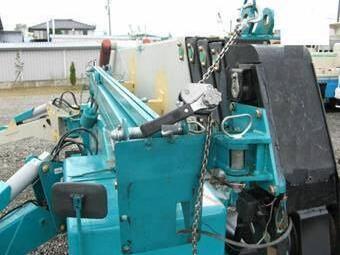
Rotary Pin
Stowage Pin (R) Stowage Pin (F) Rotary Pin (One pin for common usage )
7) Pull out stowage pin (R). Then remove lever block.
Pull out stowage pin (R) Remove lever block
8) Lift up fly-jib tip to take it out from stow bracket, then slew it around the rotary pin.
Caution
・Do not forget to detach the lever block before slewing fly-jib, otherwise it may be damaged.
9) Set the lever block as indicated by ☆mark to raise fly-jib kit up.
Information
・Set the lver block such that its handle comes to fly-jib side, which shall not interfere the movement of rod and serve easier installation.
10) Fasten boom bracket to main-boom using 4 sets of M12 bolts and nuts. Tighten them to torque of 93Nm (±13Nm).
Danger
・To prevent fly-jib to fall off, be sure to tighten and fix fly-jib fix bolt at tightening torque of 93Nm. ・Check that bolt is not cracked, squashed, or stretched before use.
Advice
・For Lever Block usage, please read the attached operation manual thoroughly.
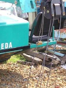
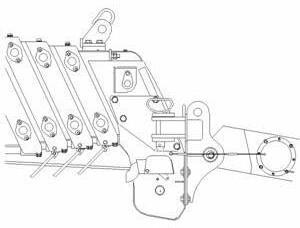
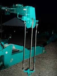
11) Remove long fix pins which secure the rod in stowed position, then fix rod to a position by a fix pin. Next, lower fly-jib by lever block and fix another end of rod to ß position by a fix pin.
12) When the rod is fastened by fix pins, insert snap retainers into tips of fix pins to prevent them missing. Then detach the lever block.
Caution
・Follow the instruction on decal, and insert pin from the direction shown in the picture on the right.
13) Detach single fall hook from hook holder, then pull out No.2 sub-boom. Remove a fix pin at γ position and extend it to full length.
(Use a handle in the tip for easier pull.) During this practice, hoist down the hook at the simultaneously. Finally, insert the fix pin (short) to No1 boom and set a snap retainer, then the installation is complete.
WARNING
・Prior to crane operation, always check that each of fix pins is not lost nor bolts are not loose.
・Prior to crane operation, always hoist the hook up to ensure that hook stops when it touches the protect weight.
・Moment limiter computes working radius with the provision that No.2 sub-boom is fully extended. Hence, No.2 sub-boom should be in full length during its operation.
Refer to "4-3. Over Hoist Detector setting" for details of over hoist detector.
※fly-jib stowage
Stow the fly-jib kit by a procedure, reverse to installation practice.
4.2 Change to single fall hook from main-boom hook block
This section specifies the procedure to change hoist wire form main-boom block, which covers both 2 and 4 wire falls, to single fall hook for fly-jib.
1) Raise the boom to the angle of five degrees and un-wind the winch so that the block reaches the ground.
Then lower the boom to horizontal level and also use boom retract switch at the same time, to take block down slowly on the ground.
2) Extract wedge socket pin and detach the wedge socket.
3) Detach wire clip.
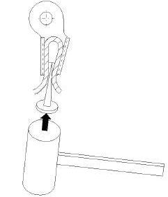
4) Remove rope wedge from wedge socket and detach wire rope. (Fit a large nail or spike to rope wedge and hammer to the direction as indicated by arrow in the figure to detach the rope wedge.)
5) Extract the wire rope from protect weight, attached to protect rope. Detach protect rope and weight of over hoist detector.
6) Extend main-boom for approximately 70 mm. then fix rotary bracket to the right side of boom head. (Use four M12X25L bolts and f 26 washers for fix.)
7) Move the fix pin (A) for rod to the ☆ marked position, then move rod and boom bracket backward. The boom bracket shall come to vertically positioned.
Advice
・Remove rotary bracket before operating with main boom.
8)Set the lever block to ※ marked positions. Adjust the position of boom bracket so that its shaft holes shall fit within rotary bracket, by the lever block.
9)Retract the main-boom to the limit.
Caution
・When retracting main-boom to the limit, adjust the angle of fly-jib assembly such that shaft holder of boom bracket shall come between two plates of rotary bracket, otherwise, both brackets may be damaged.

10) Align rotary bracket shaft holes and boom bracket shaft holes, then inert the rotary pin. Rotary pin is also used as stowage pin (F), so remove rotary pin (F) and use it. For easier removal of the rotary pin (F), use lever block to hoist and tilt Fly-Jib. Insert snap retainer to the pin subsequently to prevent missing.
11) Install fly-jib. Refer to "4-1. fly-jib Installation" for details.
※After fly-jib is installed
Stowage pin (F)
Rotary pin, used also as stowage pin (F)
12) Put hoist wire through wire hole in boom bracket of fly-jib.
13) Put hoist wire through hook holder and guide sheave groove of fly-jib.
Boom bracket wire hole
Boom bracket Guide sheave Hook holder
14) Append two protect ropes (700L) with protective weight to shackles of fly-jib. Protect rope for right side shall be appended to over hoist detector while left side to a plate hanged to boom. Put the hoist wire through a hole of protect weight.
Over hoist detector
Protect rope appending
Plate
Protect rope (700L)
Protect weight (Only for fly-jib)
15) Fix the end of wire rope to wedge socket. Fit wire rope to wedge socket and pull wire rope hard to the direction as an arrow indicates, to fix firmly.
(Wedge socket and rope wedge shall be diverted from main-boom hook block use to this single fall hook use.)

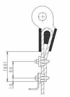
16) Fasten wire clips as shown in the figure, right. One clip shall be fastened 10 mm from one end of wire rope and weight stopper shall be fastened together.
17) Fasten wedge socket to single fall hook by a wedge socket pin. To prevent the pin to be left, fasten a high-tension washer with a bolt (M8 X 12L).
Warning
・Prior to crane operation, always hoist the hook up to ensure that hook stops when it touches the protect weight.
・Prior to crane operation, always divert over hoist detector harness and protect weight which will prevent hazardous accident such as drop down of hook or load.
Refer to "4-3. Over Hoist Detector setting" for details of Over Hoist Detector. ※Change from single fall hook to main-boom hook block for 2 or 4 falls shall be achieved in reverse order.
4.3 Diverting over hoist detector harness and protect weight
When the boom configuration is changed from main-boom to fly-jib and vice versa, it is essential that hoist detector harness and protect weight are diverted.
Warning
・Prior to crane operation, always hoist the hook up to ensure that hook stops when it touches the protect weight.
・Prior to crane operation, always divert over hoist detector harness and protect weight which will prevent hazardous accident such as drop down of hook or load.
ⅰRe-configuration from main-boom to fly-jib assembly.
1) Disconnect the faston terminal (of red harness) from over hoist detector at the tip of No.5 boom and remove protect weight for main -boom from over hoist detector, in addition. (This protect weight is only for main-boom use.)
2) Connect a cord reel and harness inside main boom by an extension cord. This extension cord should be pushed into main-boom through the hole.
・After connecting extension cord, try a slewing of fly-jib to check that wiring stands no excessive tension. Such tension may result wire breakage.
3) Attach protect weight for fly-jib. Protect ropes shall be appended to shackles of over hoist detector and plate respectively.
ⅱ:Re-configuration to main-boom from fly-jib kit. The above procedure 1) to 3) shall be practiced in reverse order.
4.4 Instruction for Fly-Jib operation
Danger
・For safety, always turn the operation mode of moment limiter to fly-jib operation, prior to start its operation. Operation in improper mode may cause serious accidents such as tipping.
・Pick and carry by fly-jib is strictly prohibited since it shall result serious hazards such as tipping or machine damage.
ⅰ:Moment limiter mode change
1) Turn operation select switch to crane mode.

2) Push Fall mode selector switch for 2 seconds or more. Operation mode shall change as shown below. Keep in mind that the switch should be once released and re-push to proceed to next mode, Mode (Wire fall indicator LED combination)
Single fall ("1" lits only)
↓
2 falls ("2" lits only)
↓
4 falls ("4" lits only)
Searcher hook (all LEDs lit)
Fly-jib ("1" flashes only)
Fall Mode LED (Only "1" flashes)
Fall mode selector switch
Boom length display (Indicates boom length and "Jib", alternately.)
In fly-jib mode, boom length display indicates boom length and "Jib", alternately. Now fly-jib operation is ready for practice.
WARNING
・Always fully extend two stages of fly-jib in use, because moment limiter's fly-jib mode computes working radius and lifting height on basis of full length and so indicated. Hence, it fails to indicate correct working radius in the event that fly-jib is retracted; that may result serious accident.
ⅱ:Instruction for operation
DANGER
・Fly-jib operation causes bigger risks of tipping or shaking of load, because longer boom shall be affected more by inertia or wind. Hence, fly-jib operation should be in decelerated mode, but never be in accelerated.
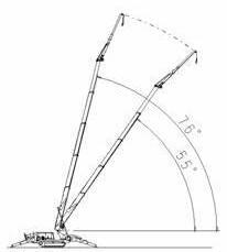
Both manual operation lever and remote control are available, also, as normal operation. However, main-boom angle and length is restricted for fly-jib operation.
Total rated load for fly-jib operation is restricted by main-boom angle, regardless of the length.
Operation range: 76°~55°
The warring signs below comes out to prohibit operations out of the range. Boom should be immediately restored to operation range (72°~57°).
Indication:
Rated load display of moment limiter shall indicate "E-J".
Red light of rotary lamp shall lit and rotate.
All the values shall be put out except Boom angle display and Rated load display. Boom raise over 76° is prohibited.
Boom lower and extend under 55°(at boom length 12.5 meters or longer) is prohibited.
Refer to "5. Moment limiter control" for details of moment limiter output.
Flashes
Indicate
・For stowing fly-jib, main-boom could be lowered to the angle less than 55°and extended under the condition that boom length is less than 12.5 meters. However, such condition is very dangerous because Rated load display or Actual load display do not work. Never lift load under such condition, otherwise critical accident or damage to fly-jib shall result.
Main-boom is allowed to be stowed only under the condition below in fly-jib mode.
Boom length must be less than 12.5 meters (Two stages of main boom are fully extended in maximum.)
Under this condition, boom lowering is available. For stowing, retract the boom first, then control the boom to stow position. In any event, however, lifting in such configuration is prohibited because Rated load display of moment limiter only indicates "E-J".
5. Moment limiter control
・For safety, always turn the operation mode of moment limiter to fly-jib operation, prior to start its operation. Operation in improper mode may cause serious accidents such as breakage of wire rope, tipping and/or damage to fly-jib.
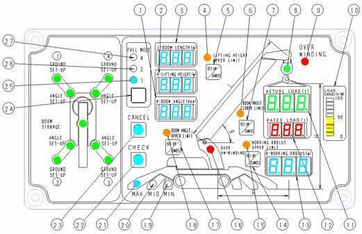
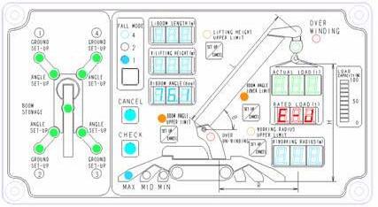
5.1 Moment limiter display
1. Boom angle display
2. Lifting height display
3. Boom length display
4. Boom lifting height upper limit LED (Orange)
5. Boom lifting height upper limit switch
6. Boom angle lower limit LED (Orange)
7. Boom angle lower limit switch
8. Load factor LED (changes color from green to yellow and red)
9. Over winding LED (Red)
10. Load capacity display
11. Actual load display
12. Rated load display
13. Working radius display
14. Working radius upper limit switch
15. Working radius upper limit LED (Orange)
16. Over un-winding LED (Orange)
17. Boom angle upper limit switch
18. Boom angle upper limit LED (Orange)
19. Outrigger MIN. set-up LED (Blue)
20. Outrigger MID. set-up LED (Blue)
21. Outrigger MAX. set-up LED (Blue)
22. Check switch
23. Cancel switch
24. Fall mode selector switch
25. Single wire fall LED (Blue)
26. Two wires fall LED (Blue)
27. Four wires fall LED (Blue)
※For general operation, refer to MC-405C Operation manual (Standard).
5.2 Items of moment limiter restriction for operation
ⅰ:Operation control by moment limiter. Moment limiter is just for emergency. Operation depending on it may rather cause hazards. Always be careful to avoid automatic stop of crane operation.
DANGER
In case of automatic stop of crane operation due to over-load, operations as below are strictly prohibited which may cause hazards such as tipping of crane or breakage of boom. ・Boom lowering ・Boom extending ・Hoist hook up
Under conditions as below, moment limiter shall control operations: ⅱ:Restriction in fly-jib mode.
(1)Restrict operation under over-load condition.
(2)Working range restriction by optional control by a operator.
(3)Restriction by over hoist detector.
(4)Restriction of slewing and boom angle range in pick and carry mode.
(5)Restriction of boom working range in fly-jib mode.
Among these items, (1) to (4) are covered by MC-405C Operation manual (Standard). All the operators and maintenance technicians should read this standard manual carefully for thorough understand before actual operation, inspection and maintenance.
In fly-jib mode, practicable working range is restricted. (refer to "2. Working Range and Total Rated Load Charts" for working range of fly-jib operation.)
DANGER
・Any crane operation under conditions that moment limiter's load capacity display indicates 90% or higher must only be practiced carefully in decelerated mode with low engine revolutions. If engine is in high revolutions or crane is operated in accelerated mode, lifted load may shake to be over range which may result hazards such as tipping of crane of breakage of boom.
・In fly-jib mode, main-boom angle is restricted within safety operation range. Any operation beyond the range shall result boom breakage or crane tipping. Be careful and confirm the correct angle during crane operations.
① Boom angle restriction
Operation range of fly-jib mode is restricted by main-boom angle, regardless of the extended length. Keep operation within the range. Operation range: 76°~55°
Detail of restriction is as specified below:
1) Boom angle 72°~57°(Safety range)
While main-boom angle is within this range, indicators below on moment limiter control panel shall lit simultaneously:
Boom angle upper limit LED (Orange)
・Boom angle lower limit LED (Orange)
This shows normal operating condition.
Boom angle upper limit LED, ON
Boom angle lower limit LED, ON
2) Boom angle 76°~72°(Pre-warning range of boom angle upper limit)
While main-boom angle is within this range, indicator below on moment limiter display shall flash.
・Boom angle upper limit LED
At the same time warning buzzer beeps intermittently to notice the operator and others that the boom is reaching the limit. (Boom angle lower limit LED lit flash.)
3) Boom angle approx. 76°(Boom angle upper limit range)
While main-boom angle is within this range, indicator below on moment limiter display shall flash.
・Boom angle upper limit LED
In addition, all the values shall be put out except Boom angle display and Rated load display. Also, rated load display shall indicate "E-J".
Red light of working status lamp shall lit and rotate, as well as warning buzzer beeps continuously. Boom raising is automatically interrupted, then.
In such event, lower the boom to the safety range from restricted zone. Boom raise operation shall be interrupted until the boom, lowered reaches safety range.
Only Boom angle display is ON
Rated load display indicates Boom angle upper limit LED, flashing
4)Boom angle 57°~55°(Lower marginal range of boom angle)
While main-boom angle is within this range, indicator below on moment limiter display shall flash.
・Boom angle lower limit LED
At the same time warning buzzer beeps intermittently to notice the operator and others that the boom is reaching the limit. (Boom angle upper limit LED shall lit flash.)
5) Boom angle approx.55°(Boom angle lower limit range)
While main-boom angle is within this range, indicator below on moment limiter display shall flash:
Boom angle upper limit LED
In addition, all the values shall be put out except Boom angle display and Rated load display. Also, rated load display shall indicate "E-J".
Red light of working status lamp shall lit, as well as warning buzzer beeps continuously. Boom lowering and extending are automatically interrupted, then. (When the boom length is 12.5 meters or less, boom can be lowered for the purpose of stowing boom.)
Only Boom angle display is ON
In such event, raise the boom to the safety range from restricted zone. Boom lowering operation shall be interrupted until the boom, raised reaches safety range.
Rated load display indicates "E-J"
Boom angle lower limit LED, flashing
② Restriction for boom stowing operation
In fly-jib mode, though crane operation is not available when main-boom angle is less than 55°, boom can be lowered for the purpose of stowing boom when the boom length is 12.5 meters or less (; two stages of main boom are fully extended in maximum).
Moment limiter display is "E-J" as it indicates in case of boom angle lower limit range. In addition, red light of working status lamp shall lit and rotate.
In such condition, when the main-boom is retracted to 12.5 meters or less, boom can be lowered without beeping of warning buzzer.
However, moment limiter only indicates "E-J" and Actual load display is not available. Except that boom length display indicates "JIb", moment limiter only displays "E-J" in boom angle display and rated load display, as it indicates in case of boom angle lower limit range.
・For stowing fly-jib, main-boom could be lowered to the angle less than 55°and extended under the condition that boom length is less than 12.5 meters. However, such condition is very dangerous because Rated load display or Actual load display do not work. Never lift load under such condition, otherwise critical accident of damage to fly-jib shall result.