61 minute read
INFORMATION TO THE OPERATION AND MAINTENANCE MANUAL R 944 B Litronic


This Operation and Maintenance Manual is valid for R 944B Litronic excavators from the following serial numbers :
We recommend that you fill in the following table as soon as you receive your excavator. This will also be helpful when you order parts
Product Id. No. (PIN No.) :
Manufacturing Date : CE 2004 conditions are not changed in any way by instructions in this manual..
Delivery Date : . . / . . / . .
This excavator meets EC Safety guidelines 98/37/EWG, 89/336/EWG, 91/368/EWG and 93/44/EWG. Noise emission data has been measured according to EC guidelines 2000/14/EG.
We reserve the right to make any technical changes compared to data and illustrations given in this manual.
Instructions and photos or drawings in this manual may not be reproduced, used for any reason and / or distributed without written permission from the publisher. All rights reserved.
Û²¹·²»
¿²¼
Í©·²¹ Ü®·ª»
Ô·»¾¸»®®ô »¿´»¼ ·²¹´» ®¿½» ¾¿´´ ¾»¿®·²¹ ©·²¹ ®·²¹ô ·²¬»®²¿´ ¬»»¬¸ Í©·²¹ °»»¼ ð›êôì ïñ³·² ¬»°´»Í©·²¹ ¬±®¯«» ïïîôé µÒ³ ر´¼·²¹ ¾®¿µ» ©»¬ ³«´¬·ó¼·½ ø°®·²¹ ¿°°´·»¼ô °®»«®» ®»´»¿»¼÷ Ñ°¬·±² °»¼¿´ ½±²¬®±´´»¼ °±·¬·±²·²¹ ¾®¿µ»
Ñ°»®¿¬±® Ý¿¾
Ý¿¾ ¾«·´¬ º®±³ ¼»»° ¼®¿©² ½±³°±²»²¬ô ®»·ó ´·»²¬´§ ³±«²¬»¼ô ±«²¼ ·²«´¿¬»¼ô ¬·²¬»¼ ©·²¼±©ô º®±²¬ ©·²¼±© ¬±®» ±ª»®¸»¿¼ô ¼±±® ©·¬¸ ´·¼·²¹ ©·²¼±©
ا¼®¿«´·½ °«³° º±® ¿¬¬¿½¸³»²¬
¬®¿ª»´
¿²¼
°«³° º´±© î ¨ îêð ´ñ³·²
¿¬·±²ô ¿«¬±³¿¬·½ ±·´ º´±© ±°¬·³·¦»® ا¼®¿«´·½ °«³° º±® ©·²¹ ¼®·ª»
®»ª»®·¾´»ô ª¿®·¿¾´» º´±©ô ©¿¸ °´¿¬» °«³°ô ½´±»¼ó´±±° ½·®½«·¬
Ó¿¨ò º´±© ïìë ´ñ³²
Ó¿¨ò °®»«®» íë𠾿® ا¼®¿«´·½ ¬¿²µ ììð ´ Ø§¼®¿«´·½ §¬»³ êèð ´ Ø§¼®¿«´·½ ±·´ º·´¬»® ï º«´´ º´±© º·´¬»® ·² ®»¬«®² ´·²» ©·¬¸ ·²¬»¹®¿¬»¼ º·²» º·´¬»® ¿®»¿ øë ³³÷ ا¼®¿«´·½ ±·´ ½±±´»®
½±³°¿½¬ ½±±´»®ô ½±²·¬·²¹ ±º ¿ ©¿¬»® ¿²¼ ¿ ¸§¼®¿«´·½ ±·´ ½±±´»® ¿²¼ ¸§¼®±ó
¬¿¬·½¿´´§ ¼®·ª»² º¿² ÓÑÜÛ »´»½¬·±² ¿¼¶«¬³»²¬ ±º ³¿½¸·²» °»®º±®³¿²½»
¿²¼ ¬¸» ¸§¼®¿«´·½ ª·¿ ¿ ³±¼» »´»½ó
¬±® ¬± ³¿¬½¸ ¿°°´·½¿¬·±²
Ô×ÚÌ º±® ´·º¬·²¹
Ú×ÒÛ º±® °®»½··±² ©±®µ ¿²¼ ´·º¬·²¹ ¬¸®±«¹¸ ª»®§ »²·¬·ª» ³±ª»³»²¬
ÛÝÑ º±® »°»½·¿´´§ »½±²±³·½¿´ ¿²¼ »²ª·ó ®±²³»²¬¿´´§ º®·»²¼´§ ±°»®¿¬·±²
ÐÑÉÛÎ º±® ³¿¨·³«³ ¼·¹¹·²¹ °±©»® ¿²¼
¸»¿ª§ ¼«¬§ ¶±¾
ÎòÐòÓ ¿¼¶«¬³»²¬ ¬»°´» ¿¼¶«¬³»²¬ ±º »²¹·²» ±«¬°«¬ ª·¿ ¬¸» ®ò°ò³ò ¿¬ »¿½¸ »´»½¬»¼ ³±¼»
ا¼®¿«´·½ ݱ²¬®±´
б©»® ¼·¬®·¾«¬·±² ª·¿ ³±²±¾´±½µ ½±²¬®±´ ª¿´ª» ©·¬¸
·²¬»¹®¿¬»¼ ¿º»¬§ ª¿´ª»
Ú´±© «³³¿¬·±² ¬± ¾±±³ ¿²¼ ¬·½µ
Ý´±»¼ó´±±° ½·®½«·¬ º±® «°°»®½¿®®·¿¹» ©·²¹ ¼®·ª»
Í»®ª± ½·®½«·¬ ߬¬¿½¸³»²¬ ¿²¼ ©·²¹
› °®±°±®¬·±²¿´ ª·¿ ¶±§¬·½µ ´»ª»®
Ì®¿ª»´ › °®±°±®¬·±²¿´ ª·¿ º±±¬ °»¼¿´ ±® ®»³±ª¿¾´» ¸¿²¼ ´»ª»® ß¼¼·¬·±²¿´ º«²½¬·±² ª·¿ º±±¬ °»¼¿´ ±® ¶±§¬·½µ ¬±¹¹´» ©·¬½¸
Ñ°»®¿¬±® »¿¬ ¸±½µ ¿¾±®¾·²¹ «°»²·±²ô ¿¼¶«¬¿¾´» ¬± ±°»®¿¬±® ©»·¹¸¬ô ê󩿧 ¿¼¶«¬¿¾´» »¿¬ ©·¬¸ ³±«²¬¿¾´» ¸»¿¼ ®»¬ Ö±§¬·½µ ·²¬»¹®¿¬»¼ ·²¬± ¿¼¶«¬¿¾´» »¿¬ ½±²±´»Ó±²·¬±®·²¹ ³»²« ¼®·ª»² ¯«»®§ ±º ½«®®»²¬ ±°»®¿¬·²¹ ½±²¼·¬·±² ª·¿ ¬¸» ÔÝÜ ¼·°´¿§ò ß«¬±ó ³¿¬·½ ³±²·¬±®·²¹ô ¼·°´¿§ô ©¿®²·²¹ ø¿½±«¬·½¿´ ¿²¼ ±°¬·½¿´ ·¹²¿´÷ ¿²¼ ¿ª·²¹ ³¿½¸·²» ³¿´º«²½¬·±² ¼¿¬¿ô º±® »¨¿³°´»ô »²¹·²» ±ª»®¸»¿¬·²¹ô ´±© »²¹·²» ±·´ °®»ó «®» ±® ´±© ¸§¼®¿«´·½ ±·´ ´»ª»´ Ø»¿¬·²¹ §¬»³ ¬¿²¼¿®¼ ¿·® ½±²¼·¬·±²·²¹ô ½±³¾·²»¼ ½±±´»®ñ¸»¿¬»®ô ¿¼¼·¬·±²¿´ ¼«¬ º·´¬»® ·² º®»¸ ¿·®ñ®»½·®½«´¿¬»¼ Ò±·» »³··±² ×ÍÑ êíçê Ô°ß ø·²·¼» ½¿¾÷ã éé ¼Þøß÷ îðððñïìñÛÝ Ô©ß ø«®®±«²¼ ²±·»÷ã ïðé ¼Þøß÷
˲¼»®½¿®®·¿¹»
Ê»®·±²æ ØÜóÍ ¸»¿ª§ ¼«¬§ô ²¿®®±© ¹¿«¹»
ØÜóÍÔ ¸»¿ª§ ¼«¬§ô ©·¼» ¹¿«¹»
Ü®·ª» Ô·»¾¸»®® ©¿¸ °´¿¬» ³±¬±® ©·¬¸ ·²¬»ó ¹®¿¬»¼ ¾®¿µ» ª¿´ª» ±² ¾±¬¸ ·¼»Ì®¿²³··±² Ô·»¾¸»®® °´¿²»¬¿®§ ®»¼«½¬·±² ¹»¿®Ì®¿ª»´ °»»¼ ´±© ®¿²¹»›íôî µ³ñ¸ ¸·¹¸ ®¿²¹»›ëôð µ³ñ¸
Ü®¿©¾¿® °«´´ ³¿¨ò ííê µÒ Ì®¿½µ ½±³°±²»²¬ Ü éô ³¿·²¬»²¿²½»óº®»»
Ì®¿½µ ®±´´»®ñ ½¿®®·»® ®±´´»® çñî
Ì®¿½µ »¿´»¼ ¿²¼ ¹®»¿»¼
Ì®¿½µ °¿¼ ¬®·°´» ¹®±«»®
Ü·¹¹·²¹ ´±½µ ©»¬ ³«´¬·ó¼·½ ø°®·²¹ ¿°°´·»¼ô °®»«®» ®»´»¿»¼÷
Þ®¿µ» ª¿´ª» ·²¬»¹®¿¬»¼ ·²¬± ¬®¿ª»´ ³±¬±® ߬¬¿½¸³»²¬
̧°» ½±³¾·²¿¬·±² ±º ®»·¬¿²¬ ¬»»´ °´¿¬» ¿²¼ ½¿¬ ¬»»´ ½±³°±²»²¬
ا¼®¿«´·½ ½§´·²¼»® Ô·»¾¸»®® ½§´·²¼»® ©·¬¸ °»½·¿´ »¿´ó §¬»³ô ¸±½µ ¿¾±®¾»¼
зª±¬ »¿´»¼ô ´±© ³¿·²¬»²¿²½»
Ô«¾®·½¿¬·±² »¿·´§ ¿½½»·¾´» ½»²¬®¿´·¦»¼ ´«¾®·½¿¬·±²
ا¼®¿«´·½ ½±²²»½¬·±² °·°» ¿²¼ ¸±» »¯«·°°»¼ ©·¬¸ ÍßÛ °´·¬ó º´¿²¹» ½±²²»½¬·±²Þ«½µ»¬ ¬¿²¼¿®¼ »¯«·°°»¼ ©·¬¸ îð ¬ ´·º¬·²¹ »§»
´»²¹¬¸²»½µ´·½¿´´§·½¿´´§Ù±±»ó ¾±±³¿¼¶«¬¿¾´»¿¼¶«¬¿¾´»²»½µ êôíð ³¾±±³¾±±³¾±±³ ìôëð ³ìôëð ³êôèð ³
³³³³³³³³³
Êîôïðéìððèëððéçððèîðð îôêðêêëðéïððéîððéëëð íôíðëèëðêêððêêððêçðð ìôïðëìððêðððêðððêíðð Éîôïðíêððííëðííéëíîðð îôêðíìððíìëðííëðíîðð íôíðíëëðíéððíìððíìðð ìôïðíèëðìðððíéëðíèðð Èîôïðïðçëðïïçððïïìððïïëðð îôêðïðçððïïçððïïìððïïëðð íôíðïðçëðïïçððïïìððïïìëð ìôïðïïðððïïèëðïïíëðïïìðð
Ü·¹¹·²¹ »²ª»´±°»
Ñ°»®¿¬·²¹ É»·¹¸¬ ¿²¼ Ù®±«²¼ Ю»«®»
Ý«¬¬·²¹ ©·¼¬¸³³éððèððí÷ çððïðëðïîððïíëðïëððïêëðïêëðïèððï÷ Ý¿°¿½·¬§ ×ÍÑ éìëï³í ðôéððôêððôçðïôïðïôíðïôëðïôéëïôçëîôîðîôêð ïôèðïôèðïôèðïôèðïôèðïôèðïôèðïôèðïôëðïôîð ïôèðïôèðïôèðïôèðïôèðïôèðïôèðïôèðïôëðïôîð
Æ îðµ¹çêëïíèðïðéðïïèëïîéðïíçðïìíëïëéëïêíëïêëð
©·¬¸ Ô·»¾¸»®® ¬»»¬¸ Æ îðî÷ µ¹ïðìð›ïïëðïîêðïíêðïììëïëîëïêéð›› Ó¿¨ò ¬·½µ ´»²¹¬¸ º±® ³¿½¸·²» ¬¿¾·´·¬§ °»® ×ÍÑ ïðëêéæ
ØÜóÍ «²¼»®½¿®®·¿¹»³ìôïðìôïðìôïðìôïðìôïðíôíðîôêðîôïðîôïðîôïð ØÜóÍÔ «²¼»®½¿®®·¿¹»³ìôïðìôïðìôïðìôïðìôïðìôïðíôíðîôêðîôêðîôêð ï÷ É·¬¸ Ô·»¾¸»®® ¬»»¬¸ Æ ïê î÷ Ú±® ¿°°´·½¿¬·±² ±ª»® «®º¿½» ½´¿ êô ¿½½±®¼·²¹ ¬± ÊÑÞô °¿®¬ Ýô Ü×Ò ïèíðð í÷ η°°»® ¾«½µ»¬ ©·¬¸ ¬»»¬¸ ·¦» êï
Ò±¬»
Ñ°¬·±²¿´ ·¼» ½«¬¬»® ©·¬¸ ¬»»¬¸ îð ·²½®»¿» ½«¬¬·²¹ ©·¼¬¸ ¾§ ¿°°®±¨ò ïìð ³³ò › É»´¼ó±² »¬ ±º ¿¼¿°¬»®› Í»¬ ±º ¾±´¬ó±² ·¼» ½«¬¬»®
ØÜóÍ ïðôë ØÜóÍÔ
©·¬¸ ¬·½µ îôïð ³
ØÜóÍ ïðôë ØÜóÍÔ ØÜóÍ çôð ØÜóÍÔ ØÜóÍ éôë ØÜóÍÔ ØÜóÍ êôð ØÜóÍÔ ØÜóÍ ìôë ØÜóÍÔ ØÜóÍ íôð ØÜóÍÔ ØÜóÍ ïôë ØÜóÍÔ ØÜóÍ ð ØÜóÍÔ ØÜóÍ › ïôë ØÜóÍÔ
©·¬¸ ¬·½µ îôêð ³
ØÜóÍ ïðôë ØÜóÍÔ ØÜóÍ çôð ØÜóÍÔ ØÜóÍ éôë ØÜóÍÔ ØÜóÍ êôð ØÜóÍÔ ØÜóÍ ìôë ØÜóÍÔ ØÜóÍ íôð ØÜóÍÔ ØÜóÍ ïôë ØÜóÍÔ ØÜóÍ ð ØÜóÍÔ ØÜóÍ › ïôë ØÜóÍÔ ØÜóÍ › íôð ØÜóÍÔ ØÜóÍ › ìôë ØÜóÍÔ ØÜóÍ › êôð ØÜóÍÔ
Ý¿°¿½·¬·» ¿®» ª¿´·¼ º±® êðð ³³ ©·¼» ¬®·°´» ¹®±«»® °¿¼ò ײ¼·½¿¬»¼ ´±¿¼ ¿®» ¾¿»¼ ±² ×ÍÑ ïðëêé ¬¿²¼¿®¼ ¿²¼ ¼± ²±¬ »¨½»»¼ éëû ±º ¬·°°·²¹ ±® èéû ±º ¸§¼®¿«´·½ ½¿°¿½·¬§ ø·²¼·½¿¬»¼ ª·¿ ý÷ò
Ó¿¨·³«³ ´±¿¼ º±® ¬¸» ¾¿½µ¸±» ¾«½µ»¬ ´·º¬·²¹ »§» · îð ¬ò
¾«½µ»¬ øïôïð ³í÷ô ¬¸» ´·º¬ ½¿°¿½·¬·» ©·´´ ·²½®»¿» ¾§ ïïèë µ¹ô ©·¬¸±«¬ ¾«½µ»¬ ½§´·²¼»®ô ´·²µ ¿²¼ ´»ª»® ¬¸»§ ·²½®»¿» ¾§ ¿² ¿¼¼·¬·±²¿´ ìçð µ¹ò Ô·º¬·²¹ ½¿°¿½·¬§ ±º ¬¸» »¨½¿ª¿¬±® · ´·³·¬»¼ ¾§ ³¿½¸·²» ¬¿¾·´·¬§ô ¸§¼®¿«´·½ ½¿°¿½·¬§ ¿²¼ ³¿¨·³«³ °»®³··¾´» ´±¿¼ ±º ¬¸»
´±¿¼ ¸±±µò
ɸ»² ´·º¬·²¹ ´±¿¼ô ¬¸» ¸§¼®¿«´·½ »¨½¿ª¿¬±® ³«¬ ¾» »¯«·°°»¼ ©·¬¸ ¿«¬±³¿¬·½ ½¸»½µ ª¿´ª» ±² ·¬ ¸±·¬ ½§´·²¼»® ¿²¼ ±ª»®ó ´±¿¼ ©¿®²·²¹ ¼»ª·½» ¿½½±®¼·²¹ ¬± Û«®±°»¿² ͬ¿²¼¿®¼ô ÛÒ ìéìóëò
Ü·¹¹·²¹ »²ª»´±°»
¾¿·½ ³¿½¸·²» ©·¬¸ ìôëð ³ ¸§¼®¿«´·½¿´´§ ¿¼¶«¬¿¾´» ¾±±³ô îôêð ³ ¬·½µ ¿²¼ ïôèð ³í ¾«½µ»¬ò
Ñ°¬·±²¿´æ
Þ«½µ»¬
©·¼¬¸³³éððèððí÷ çððïðëðïîððïíëðïëððïêëðïêëðïèððï÷ ðôéððôêððôçðïôïðïôíðïôëðïôéëïôçëîôîðîôêð ïôèðïôèðïôèðïôèðïôèðïôèðïôèðïôèðïôëðïôîð ïôèðïôèðïôèðïôèðïôèðïôèðïôèðïôèðïôëðïôîð îðµ¹çêëïíèðïðéðïïèëïîéðïíçðïìíëïëéëïêíëïêëð µ¹ïðìð›ïïëðïîêðïíêðïììëïëîëïêéð››
´»²¹¬¸ º±® ³¿½¸·²» ¬¿¾·´·¬§ °»® ×ÍÑ ïðëêéæ
ØÜóÍ «²¼»®½¿®®·¿¹»³ìôïðìôïðìôïðìôïðìôïðíôíðîôêðîôïðîôïðîôïð ØÜóÍÔ «²¼»®½¿®®·¿¹»³ìôïðìôïðìôïðìôïðìôïðìôïðíôíðîôêðîôêðîôêð ï÷ É·¬¸ Ô·»¾¸»®® ¬»»¬¸ Æ ïê î÷ Ú±® ¿°°´·½¿¬·±² ±ª»® «®º¿½» ½´¿ êô ¿½½±®¼·²¹ ¬± ÊÑÞô °¿®¬ Ýô Ü×Ò ïèíðð í÷ η°°»® ¾«½µ»¬ ©·¬¸ ¬»»¬¸ ·¦» êï
Ò±¬»
Ñ°¬·±²¿´ ·¼» ½«¬¬»® ©·¬¸ ¬»»¬¸ îð ·²½®»¿» ½«¬¬·²¹ ©·¼¬¸ ¾§ ¿°°®±¨ò ïìð ³³ò
› É»´¼ó±² »¬ ±º ¿¼¿°¬»®
› Í»¬ ±º ¾±´¬ó±² ·¼» ½«¬¬»®
©·¬¸ ¬·½µ îôïð ³
ïðôë ØÜóÍÔ ØÜóÍ çôð ØÜóÍÔ ØÜóÍ éôë ØÜóÍÔ ØÜóÍ êôð ØÜóÍÔ ØÜóÍ ìôë ØÜóÍÔ ØÜóÍ íôð ØÜóÍÔ ØÜóÍ ïôë ØÜóÍÔ ØÜóÍ ð ØÜóÍÔ ØÜóÍ › ïôë ØÜóÍÔ ØÜóÍ › íôð ØÜóÍÔ ØÜóÍ › ìôë ØÜóÍÔ ØÜóÍ › êôð ØÜóÍÔ
©·¬¸ ¬·½µ îôêð ³
©·¬¸
ØÜóÍ ïðôë ØÜóÍÔ ØÜóÍ çôð ØÜóÍÔ ØÜóÍ éôë ØÜóÍÔ ØÜóÍ êôð ØÜóÍÔ ØÜóÍ ìôë ØÜóÍÔ ØÜóÍ íôð ØÜóÍÔ ØÜóÍ ïôë ØÜóÍÔ ØÜóÍ ð ØÜóÍÔ ØÜóÍ › ïôë ØÜóÍÔ ØÜóÍ › íôð ØÜóÍÔ ØÜóÍ › ìôë ØÜóÍÔ ØÜóÍ › êôð ØÜóÍÔ
¯«±¬»¼ ·² ¾®¿½µ»¬ ¿®» ª¿´·¼ º±® ¬¸» «²¼»®½¿®®·¿¹» ©¸»² ·² ´±²¹·¬«¼·²¿´ °±·¬·±²ò Ý¿°¿½·¬·» ¿®» ª¿´·¼ º±® êðð ³³ ©·¼» ¬®·°´» ¹®±«»® °¿¼ ©·¬¸ ¿¼¶«¬·²¹ ½§´·²¼»® ·² ±°¬·³¿´ °±·¬·±²ò
ײ¼·½¿¬»¼ ´±¿¼ ¿®» ¾¿»¼ ±² ×ÍÑ ïðëêé ¬¿²¼¿®¼ ¿²¼ ¼± ²±¬ »¨½»»¼ éëû ±º ¬·°°·²¹ ±® èéû ±º ¸§¼®¿«´·½ ½¿°¿½·¬§ ø·²¼·½¿¬»¼ ª·¿ ý÷ò
Ó¿¨·³«³ ´±¿¼ º±® ¬¸» ¾¿½µ¸±» ¾«½µ»¬ ´·º¬·²¹ »§» · îð ¬ò
É·¬¸±«¬ ¾«½µ»¬ øïôïð ³í÷ô ¬¸» ´·º¬ ½¿°¿½·¬·» ©·´´ ·²½®»¿» ¾§ ïïèë µ¹ô ©·¬¸±«¬ ¾«½µ»¬ ½§´·²¼»®ô ´·²µ ¿²¼ ´»ª»® ¬¸»§ ·²½®»¿»
¾§ ¿² ¿¼¼·¬·±²¿´ ìçð µ¹ò
Ô·º¬·²¹ ½¿°¿½·¬§ ±º ¬¸» »¨½¿ª¿¬±® · ´·³·¬»¼ ¾§ ³¿½¸·²» ¬¿¾·´·¬§ô ¸§¼®¿«´·½ ½¿°¿½·¬§ ¿²¼ ³¿¨·³«³ °»®³··¾´» ´±¿¼ ±º ¬¸»
´±¿¼ ¸±±µò
ɸ»² ´·º¬·²¹ ´±¿¼ô ¬¸» ¸§¼®¿«´·½ »¨½¿ª¿¬±® ³«¬ ¾» »¯«·°°»¼ ©·¬¸ ¿«¬±³¿¬·½ ½¸»½µ ª¿´ª» ±² ·¬ ¸±·¬ ½§´·²¼»® ¿²¼ ±ª»®ó ´±¿¼ ©¿®²·²¹ ¼»ª·½» ¿½½±®¼·²¹ ¬± Û«®±°»¿² ͬ¿²¼¿®¼ô
Ü·¹¹·²¹ »²ª»´±°»
Ý«¬¬·²¹ ©·¼¬¸³³éððèððí÷ çððïðëðïîððïíëðïëððïêëðïêëðïèððï÷ ðôéððôêððôçðïôïðïôíðïôëðïôéëïôçëîôîðîôêð ïôèðïôèðïôèðïôèðïôèðïôèðïôèðïôèðïôëðïôîð ïôèðïôèðïôèðïôèðïôèðïôèðïôèðïôèðïôëðïôîð îðµ¹çêëïíèðïðéðïïèëïîéðïíçðïìíëïëéëïêíëïêëð
Ô·»¾¸»®® ¬»»¬¸ Æ îðî÷ µ¹ïðìð›ïïëðïîêðïíêðïììëïëîëïêéð›› Ó¿¨ò ¬·½µ ´»²¹¬¸ º±® ³¿½¸·²» ¬¿¾·´·¬§ °»® ×ÍÑ ïðëêéæ
ØÜóÍ «²¼»®½¿®®·¿¹»³ìôïðìôïðìôïðìôïðìôïðíôíðîôêðîôïðîôïðîôïð ØÜóÍÔ «²¼»®½¿®®·¿¹»³ìôïðìôïðìôïðìôïðìôïðìôïðíôíðîôêðîôêðîôêð ï÷ É·¬¸ Ô·»¾¸»®® ¬»»¬¸ Æ ïê î÷ Ú±® ¿°°´·½¿¬·±² ±ª»® «®º¿½» ½´¿ êô ¿½½±®¼·²¹ ¬± ÊÑÞô °¿®¬ Ýô Ü×Ò ïèíðð í÷ η°°»® ¾«½µ»¬ ©·¬¸ ¬»»¬¸ ·¦» êï
Ò±¬»
Ñ°¬·±²¿´ ·¼» ½«¬¬»® ©·¬¸ ¬»»¬¸ îð ·²½®»¿» ½«¬¬·²¹ ©·¼¬¸ ¾§ ¿°°®±¨ò ïìð ³³ò
› É»´¼ó±² »¬ ±º ¿¼¿°¬»®
› Í»¬ ±º ¾±´¬ó±² ·¼» ½«¬¬»®
©·¬¸ ¬·½µ îôïð ³
ØÜóÍ ïðôë ØÜóÍÔ ØÜóÍ çôð ØÜóÍÔ ØÜóÍ éôë ØÜóÍÔ ØÜóÍ êôð ØÜóÍÔ ØÜóÍ ìôë ØÜóÍÔ ØÜóÍ íôð ØÜóÍÔ ØÜóÍ ïôë ØÜóÍÔ ØÜóÍ ð ØÜóÍÔ
©·¬¸ ¬·½µ íôíð ³
ØÜóÍ ïðôë ØÜóÍÔ ØÜóÍ çôð ØÜóÍÔ ØÜóÍ éôë ØÜóÍÔ ØÜóÍ êôð ØÜóÍÔ ØÜóÍ ìôë ØÜóÍÔ ØÜóÍ íôð ØÜóÍÔ ØÜóÍ ïôë ØÜóÍÔ ØÜóÍ ð ØÜóÍÔ ØÜóÍ › ïôë ØÜóÍÔ ØÜóÍ › íôð ØÜóÍÔ ØÜóÍ › ìôë ØÜóÍÔ ØÜóÍ › êôð ØÜóÍÔ
©·¬¸ ¬·½µ îôêð ³
°±·¬·±²ò
Ý¿°¿½·¬·» ¿®» ª¿´·¼ º±® êðð ³³ ©·¼» ¬®·°´» ¹®±«»® °¿¼ò ײ¼·½¿¬»¼ ´±¿¼ ¿®» ¾¿»¼ ±² ×ÍÑ ïðëêé ¬¿²¼¿®¼ ¿²¼ ¼± ²±¬ »¨½»»¼ éëû ±º ¬·°°·²¹ ±® èéû ±º ¸§¼®¿«´·½ ½¿°¿½·¬§ ø·²¼·½¿¬»¼ ª·¿ ý÷ò
Ó¿¨·³«³ ´±¿¼ º±® ¬¸» ¾¿½µ¸±» ¾«½µ»¬ ´·º¬·²¹ »§» · îð ¬ò
É·¬¸±«¬ ¾«½µ»¬ øïôïð ³í÷ô ¬¸» ´·º¬ ½¿°¿½·¬·» ©·´´ ·²½®»¿» ¾§ ïïèë µ¹ô ©·¬¸±«¬ ¾«½µ»¬ ½§´·²¼»®ô ´·²µ ¿²¼ ´»ª»® ¬¸»§ ·²½®»¿» ¾§ ¿² ¿¼¼·¬·±²¿´ ìçð µ¹ò Ô·º¬·²¹ ½¿°¿½·¬§ ±º ¬¸» »¨½¿ª¿¬±® · ´·³·¬»¼ ¾§ ³¿½¸·²» ¬¿¾·´·¬§ô ¸§¼®¿«´·½ ½¿°¿½·¬§ ¿²¼ ³¿¨·³«³ °»®³··¾´» ´±¿¼ ±º ¬¸»
´±¿¼ ¸±±µò
ɸ»² ´·º¬·²¹ ´±¿¼ô ¬¸» ¸§¼®¿«´·½ »¨½¿ª¿¬±® ³«¬ ¾» »¯«·°°»¼ ©·¬¸ ¿«¬±³¿¬·½ ½¸»½µ ª¿´ª» ±² ·¬ ¸±·¬ ½§´·²¼»® ¿²¼ ±ª»®ó ´±¿¼ ©¿®²·²¹ ¼»ª·½» ¿½½±®¼·²¹ ¬± Û«®±°»¿² ͬ¿²¼¿®¼ô ÛÒ ìéìóëò
Ü·¹¹·²¹ »²ª»´±°»
Ñ°»®¿¬·²¹
çððïðëðïîððïíëðïëððïêëðïêëðïèððï÷ ðôéððôêððôçðïôïðïôíðïôëðïôéëïôçëîôîðîôêð ïôèðïôèðïôèðïôèðïôèðïôèðïôèðïôèðïôëðïôî𠳿¬»®·¿´ ©»·¹¸¬ ïôèðïôèðïôèðïôèðïôèðïôèðïôèðïôèðïôëðïôîð îðµ¹çêëïíèðïðéðïïèëïîéðïíçðïìíëïëéëïêíëïêëð
Ô·»¾¸»®® ¬»»¬¸ Æ îðî÷ µ¹ïðìð›ïïëðïîêðïíêðïììëïëîëïêéð›› º±® ³¿½¸·²» ¬¿¾·´·¬§ °»® ×ÍÑ ïðëêéæ
ØÜóÍ «²¼»®½¿®®·¿¹»³ìôïðìôïðìôïðìôïðìôïðíôíðîôêðîôïðîôïðîôïð
ØÜóÍÔ «²¼»®½¿®®·¿¹»³ìôïðìôïðìôïðìôïðìôïðìôïðíôíðîôêðîôêðîôêð ï÷ É·¬¸ Ô·»¾¸»®® ¬»»¬¸ Æ ïê î÷ Ú±® ¿°°´·½¿¬·±² ±ª»® «®º¿½» ½´¿ êô ¿½½±®¼·²¹ ¬± ÊÑÞô °¿®¬ Ýô Ü×Ò ïèíðð í÷ η°°»® ¾«½µ»¬ ©·¬¸ ¬»»¬¸ ·¦» êï
Ò±¬»
Ñ°¬·±²¿´ ·¼» ½«¬¬»® ©·¬¸ ¬»»¬¸ îð ·²½®»¿» ½«¬¬·²¹ ©·¼¬¸ ¾§ ¿°°®±¨ò ïìð ³³ò
› É»´¼ó±² »¬ ±º ¿¼¿°¬»®
› Í»¬ ±º ¾±´¬ó±² ·¼» ½«¬¬»®
ØÜóÍ ïðôë
©·¬¸ ¬·½µ îôïð ³
ØÜóÍ ïðôë ØÜóÍÔ ØÜóÍ çôð ØÜóÍÔ ØÜóÍ éôë ØÜóÍÔ ØÜóÍ êôð ØÜóÍÔ ØÜóÍ ìôë ØÜóÍÔ ØÜóÍ íôð ØÜóÍÔ ØÜóÍ ïôë ØÜóÍÔ ØÜóÍ ð ØÜóÍÔ ØÜóÍ
©·¬¸ ¬·½µ íôíð ³
ØÜóÍ ïðôë ØÜóÍÔ ØÜóÍ çôð ØÜóÍÔ ØÜóÍ éôë ØÜóÍÔ ØÜóÍ êôð ØÜóÍÔ ØÜóÍ ìôë ØÜóÍÔ ØÜóÍ íôð ØÜóÍÔ ØÜóÍ ïôë ØÜóÍÔ ØÜóÍ ð ØÜóÍÔ ØÜóÍ › ïôë ØÜóÍÔ ØÜóÍ › íôð ØÜóÍÔ ØÜóÍ › ìôë ØÜóÍÔ ØÜóÍ › êôð ØÜóÍÔ
©·¬¸ ¬·½µ îôêð ³
°±·¬·±²ò
Ý¿°¿½·¬·» ¿®» ª¿´·¼ º±® êðð ³³ ©·¼» ¬®·°´» ¹®±«»® °¿¼ò ײ¼·½¿¬»¼ ´±¿¼ ¿®» ¾¿»¼ ±² ×ÍÑ ïðëêé ¬¿²¼¿®¼ ¿²¼ ¼± ²±¬ »¨½»»¼ éëû ±º ¬·°°·²¹ ±® èéû ±º ¸§¼®¿«´·½ ½¿°¿½·¬§ ø·²¼·½¿¬»¼ ª·¿ ý÷ò
Ó¿¨·³«³ ´±¿¼ º±® ¬¸» ¾¿½µ¸±» ¾«½µ»¬ ´·º¬·²¹ »§» · îð ¬ò
É·¬¸±«¬ ¾«½µ»¬ øïôïð ³í÷ô ¬¸» ´·º¬ ½¿°¿½·¬·» ©·´´ ·²½®»¿» ¾§ ïïèë µ¹ô ©·¬¸±«¬ ¾«½µ»¬ ½§´·²¼»®ô ´·²µ ¿²¼ ´»ª»® ¬¸»§ ·²½®»¿» ¾§ ¿² ¿¼¼·¬·±²¿´ ìçð µ¹ò Ô·º¬·²¹ ½¿°¿½·¬§ ±º ¬¸» »¨½¿ª¿¬±® · ´·³·¬»¼ ¾§ ³¿½¸·²» ¬¿¾·´·¬§ô ¸§¼®¿«´·½ ½¿°¿½·¬§ ¿²¼ ³¿¨·³«³ °»®³··¾´» ´±¿¼ ±º ¬¸»
¸±±µò
ɸ»² ´·º¬·²¹ ´±¿¼ô ¬¸» ¸§¼®¿«´·½ »¨½¿ª¿¬±® ³«¬ ¾» »¯«·°°»¼ ©·¬¸ ¿«¬±³¿¬·½ ½¸»½µ ª¿´ª» ±² ·¬ ¸±·¬ ½§´·²¼»® ¿²¼ ±ª»®ó
´±¿¼ ©¿®²·²¹ ¼»ª·½» ¿½½±®¼·²¹ ¬± Û«®±°»¿² ͬ¿²¼¿®¼ô ÛÒ ìéìóëò
©·¬¸ ¬·½µ îôïð ³
©·¬¸ ¬·½µ îôêð ³
©·¬¸ ¬·½µ
³
«²¼»®½¿®®·¿¹» ©¸»² ·² ´±²¹·¬«¼·²¿´ °±·¬·±²ò Ý¿°¿½·¬·» ¿®» ª¿´·¼ º±® êðð ³³ ©·¼» ¬®·°´» ¹®±«»® °¿¼ò ײ¼·½¿¬»¼ ´±¿¼ ¿®» ¾¿»¼ ±² ×ÍÑ ïðëêé ¬¿²¼¿®¼ ¿²¼ ¼± ²±¬ »¨½»»¼ éëû ±º ¬·°°·²¹ ±® èéû ±º ¸§¼®¿«´·½ ½¿°¿½·¬§ ø·²¼·½¿¬»¼ ª·¿ ý÷ò Ó¿¨·³«³ ´±¿¼ º±® ¬¸» ¾¿½µ¸±» ¾«½µ»¬ ´·º¬·²¹ »§» · îð ¬ò É·¬¸±«¬ ¾«½µ»¬ øïôïð ³í÷ô ¬¸» ´·º¬ ½¿°¿½·¬·» ©·´´ ·²½®»¿» ¾§ ïïèë µ¹ô ©·¬¸±«¬ ¾«½µ»¬ ½§´·²¼»®ô ´·²µ ¿²¼ ´»ª»® ¬¸»§ ·²½®»¿» ¾§ ¿² ¿¼¼·¬·±²¿´ ìçð µ¹ò Ô·º¬·²¹ ½¿°¿½·¬§ ±º ¬¸» »¨½¿ª¿¬±® · ´·³·¬»¼ ¾§ ³¿½¸·²» ¬¿¾·´·¬§ô ¸§¼®¿«´·½ ½¿°¿½·¬§ ¿²¼ ³¿¨·³«³ °»®³··¾´» ´±¿¼ ±º ¬¸»
´±¿¼ ¸±±µò
ɸ»² ´·º¬·²¹ ´±¿¼ô ¬¸» ¸§¼®¿«´·½ »¨½¿ª¿¬±® ³«¬ ¾» »¯«·°°»¼ ©·¬¸ ¿«¬±³¿¬·½ ½¸»½µ ª¿´ª» ±² ·¬ ¸±·¬ ½§´·²¼»® ¿²¼ ±ª»®ó ´±¿¼ ©¿®²·²¹ ¼»ª·½» ¿½½±®¼·²¹ ¬± Û«®±°»¿² ͬ¿²¼¿®¼ô ÛÒ ìéìóëò
ØÜóÍ ïðôë ØÜóÍÔ ØÜóÍ çôð ØÜóÍÔ ØÜóÍ éôë ØÜóÍÔ
©·¬¸ ¬·½µ îôïð ³
éôë ØÜóÍÔ êôð ØÜóÍÔ ØÜóÍ ìôë ØÜóÍÔ ØÜóÍ íôð ØÜóÍÔ ØÜóÍ ïôë ØÜóÍÔ ØÜóÍ ð ØÜóÍÔ ØÜóÍ › ïôë ØÜóÍÔ ØÜóÍ › íôð ØÜóÍÔ ØÜóÍ › ìôë ØÜóÍÔ ØÜóÍ › êôð ØÜóÍÔ
¬·½µ íôíð ³
ïðôë ØÜóÍÔ ØÜóÍ çôð ØÜóÍÔ ØÜóÍ éôë ØÜóÍÔ ØÜóÍ êôð ØÜóÍÔ ØÜóÍ ìôë ØÜóÍÔ ØÜóÍ íôð ØÜóÍÔ ØÜóÍ ïôë ØÜóÍÔ ØÜóÍ ð ØÜóÍÔ ØÜóÍ › ïôë ØÜóÍÔ ØÜóÍ › íôð ØÜóÍÔ ØÜóÍ › ìôë ØÜóÍÔ ØÜóÍ › êôð ØÜóÍÔ
ØÜóÍ ïðôë ØÜóÍÔ ØÜóÍ çôð ØÜóÍÔ ØÜóÍ éôë ØÜóÍÔ ØÜóÍ êôð ØÜóÍÔ ØÜóÍ ìôë ØÜóÍÔ ØÜóÍ íôð ØÜóÍÔ ØÜóÍ ïôë ØÜóÍÔ ØÜóÍ ð ØÜóÍÔ ØÜóÍ › ïôë ØÜóÍÔ ØÜóÍ › íôð ØÜóÍÔ ØÜóÍ › ìôë ØÜóÍÔ ØÜóÍ › êôð ØÜóÍÔ
©·¬¸ ¬·½µ îôêð ³
©¸»² ·² ´±²¹·¬«¼·²¿´ °±·¬·±²ò
¿®» ª¿´·¼ º±® êðð ³³ ©·¼» ¬®·°´» ¹®±«»® °¿¼ ©·¬¸ ¿¼¶«¬·²¹ ½§´·²¼»® ·² ±°¬·³¿´ °±·¬·±²ò
ײ¼·½¿¬»¼ ´±¿¼ ¿®» ¾¿»¼ ±² ×ÍÑ ïðëêé ¬¿²¼¿®¼ ¿²¼ ¼± ²±¬ »¨½»»¼ éëû ±º ¬·°°·²¹ ±® èéû ±º ¸§¼®¿«´·½ ½¿°¿½·¬§ ø·²¼·½¿¬»¼ ª·¿ ý÷ò
Ó¿¨·³«³ ´±¿¼ º±® ¬¸» ¾¿½µ¸±» ¾«½µ»¬ ´·º¬·²¹ »§» · îð ¬ò
¾«½µ»¬ øïôïð ³í÷ô ¬¸» ´·º¬ ½¿°¿½·¬·» ©·´´ ·²½®»¿» ¾§ ïïèë µ¹ô ©·¬¸±«¬ ¾«½µ»¬ ½§´·²¼»®ô ´·²µ ¿²¼
¸§¼®¿«´·½ ½¿°¿½·¬§ ¿²¼ ³¿¨·³«³ °»®³··¾´» ´±¿¼ ±º ¬¸» ´±¿¼ ¸±±µò
ɸ»² ´·º¬·²¹ ´±¿¼ô ¬¸» ¸§¼®¿«´·½ »¨½¿ª¿¬±® ³«¬ ¾» »¯«·°°»¼ ©·¬¸ ¿«¬±³¿¬·½ ½¸»½µ ª¿´ª» ±² ·¬ ¸±·¬ ½§´·²¼»® ¿²¼ ±ª»®ó ´±¿¼ ©¿®²·²¹ ¼»ª·½» ¿½½±®¼·²¹ ¬± Û«®±°»¿² ͬ¿²¼¿®¼ô ÛÒ ìéìóëò
©·¬¸ ¬·½µ îôïð ³
©·¬¸ ¬·½µ îôêð ³
³
©·¬¸ ¬·½µ ìôïð ³
ª¿´·¼ º±® ¬¸» «²¼»®½¿®®·¿¹» ©¸»² ·² ´±²¹·¬«¼·²¿´ °±·¬·±²ò Ý¿°¿½·¬·» ¿®» ª¿´·¼ º±® êðð ³³ ©·¼» ¬®·°´» ¹®±«»® °¿¼ò ײ¼·½¿¬»¼ ´±¿¼ ¿®» ¾¿»¼ ±² ×ÍÑ ïðëêé ¬¿²¼¿®¼ ¿²¼ ¼± ²±¬ »¨½»»¼ éëû ±º ¬·°°·²¹ ±® èéû ±º ¸§¼®¿«´·½ ½¿°¿½·¬§ ø·²¼·½¿¬»¼ ª·¿ ý÷ò Ó¿¨·³«³ ´±¿¼ º±® ¬¸» ¾¿½µ¸±» ¾«½µ»¬ ´·º¬·²¹ »§» · îð ¬ò
É·¬¸±«¬ ¾«½µ»¬ øïôïð ³í÷ô ¬¸» ´·º¬ ½¿°¿½·¬·» ©·´´ ·²½®»¿» ¾§ ïïèë µ¹ô ©·¬¸±«¬ ¾«½µ»¬ ½§´·²¼»®ô ´·²µ ¿²¼ ´»ª»® ¬¸»§ ·²½®»¿»
¾§ ¿² ¿¼¼·¬·±²¿´ ìçð µ¹ò
Ô·º¬·²¹ ½¿°¿½·¬§ ±º ¬¸» »¨½¿ª¿¬±® · ´·³·¬»¼ ¾§ ³¿½¸·²» ¬¿¾·´·¬§ô ¸§¼®¿«´·½ ½¿°¿½·¬§ ¿²¼ ³¿¨·³«³ °»®³··¾´» ´±¿¼ ±º ¬¸»
´±¿¼ ¸±±µò
ɸ»² ´·º¬·²¹ ´±¿¼ô ¬¸» ¸§¼®¿«´·½ »¨½¿ª¿¬±® ³«¬ ¾» »¯«·°°»¼ ©·¬¸ ¿«¬±³¿¬·½ ½¸»½µ ª¿´ª» ±² ·¬ ¸±·¬ ½§´·²¼»® ¿²¼ ±ª»®ó ´±¿¼ ©¿®²·²¹ ¼»ª·½» ¿½½±®¼·²¹ ¬± Û«®±°»¿² ͬ¿²¼¿®¼ô ÛÒ ìéìóëò
ͬ¿²¼¿®¼ Û¯«·°³»²¬ ˲¼»®½¿®®·¿¹»
¨ Ì©±ó°»»¼ ¬®¿ª»´ ¨ Ì®¿½µ ¹«·¼» ±² ·¼´»® »²¼ ¨ Ô·º» ¬·³» ´«¾®·½¿¬»¼ ¬®¿½µ ®±´´»®
¨ Ì®¿ª»´ ¼®·ª» ½±³°´»¬»´§ ·²¬»¹®¿¬»¼ ·²¬± ¬¸» «²¼»®ó
½¿®®·¿¹» º®¿³»
¨ Ì®¿½µ »¿´»¼ ¿²¼ ¹®»¿»¼
Ë°°»®½¿®®·¿¹»
¨ Û²¹·²» ¸±±¼ ©·¬¸ ´·º¬ ¸»´°
¨ Ô±½µ¿¾´» ¬±±´ ¾±¨
¨ Ø¿²¼®¿·´ô ²±² ´·° «®º¿½»
¨ ̱±´ Õ·¬
¨ Ó¿·²¬»²¿²½»óº®»» ©·²¹ ¾®¿µ» ´±½µ
¨ Ó¿·²¬»²¿²½»óº®»» ØÜ󾿬¬»®·»
¨ Ó¿·² ©·¬½¸ º±® »´»½¬®·½ ½·®½«·¬
¨ ͱ«²¼ ·²«´¿¬·±²
¨ Ó»½¸¿²·½¿´ ©·²¹ ´±½µ «°°»®ñ´±©»®
ا¼®¿«´·½
¨ Û´»½¬®±²·½ °«³° ®»¹«´¿¬·±²
¨ ͬ»°´» ©±®µ ³±¼» »´»½¬±®
¨ Ю»«®» ¬±®¿¹» º±® ½±²¬®±´´»¼ ´±©»®·²¹ ±º ¿¬¬¿½¸³»²¬©·¬¸ »²¹·²» ¬«®²»¼ ±ºº ¨ ا¼®¿«´·½ ¬¿²µ ¸«¬ó±ºº ª¿´ª»
¨ Ю»«®» ½±³°»²¿¬·±²
¨ Ú´±© ½±³°»²¿¬·±²
¨ Ú·´¬»® ©·¬¸ ·²¬»¹®¿¬»¼ º·²» º·´¬»® ¿®»¿ øë ³³÷
¨ Ю»«®» ¬»¬ °±®¬
Û²¹·²»
¨ Ü·®»½¬ ·²¶»½¬·±²
¨ Ì«®¾± ½¸¿®¹»®
¨ Ü®§ó¬§°» ¿·® ½´»¿²»® ©ñ°®»ó½´»¿²»®ô ³¿·² ¿²¼ ¿º»¬§ »´»³»²¬
¨ Í»²±® ½±²¬®±´´»¼ »²¹·²» ·¼´·²¹
Ñ°»®¿¬±® Ý¿¾
¨ Ü»»° ¼®¿©² ½¿¾ ¸»´´ ½±³°±²»²¬
¨ ß´´ ¬·²¬»¼ ©·²¼±©
¨ ܱ±® ©·¬¸ ´·¼·²¹ô ©·²¼±© ¨ ß´´ó®±«²¼ ¿¼¶«¬¿¾´» ®±±º º´¿°
¨ ο·² °®±¬»½¬·ª» ¸¿¼» º±® º®±²¬ ©·²¼±© ¨ É¿¸»® ¿²¼ ©·°»®
¨ ê󩿧 ¿¼¶«¬¿¾´» ½´±¬¸ «°»²·±² »¿¬
¨ Í»¿¬ ¿²¼ ½±²±´» ·²¼»°»²¼»²¬´§ ¿¼¶«¬¿¾´»
¨ λ³±ª¿¾´» ¸¿²¼´» º±® ¬®¿ª»´ °»¼¿´
¨ ß·® ½±²¼·¬·±²»®
¨ ݱ¿¬ ¸±±µ
¨ ܱ³» ´·¹¸¬ ¨ Í«² ª·±®
¨ ײ·¼» ®»¿® ³·®®±®
¨ ο¼·± ·²¬¿´´¿¬·±² °®»°óµ·¬
¨ Ý·¹¿® ´·¹¸¬»® ¿²¼ ¿¸¬®¿§
¨ λ³±ª¿¾´» ½«¬±³ º´±±® ³¿¬
¨ ͬ±®¿¹» ¿²¼ Ô·¬»®¿¬«®» ¬®¿§
¨ Ü·¹·¬¿´ ·²¬®«³»²¬¿¬·±²
¨ Ü·¹·¬¿´ ·²¬®«³»²¬ º±® ±·´ ¬»³°ò »²¹·²» ÎÐÓ ¿²¼ ±·´ °®»«®»
¨ Ü·¹·¬¿´ ¸±«® ³»¬»® ª··¾´» º®±³ ±«¬·¼» ߬¬¿½¸³»²¬
¨ ݧ´·²¼»® ©·¬¸ ¸±½µ ¿¾±®¾»®
¨ Í»¿´»¼ °·ª±¬¨ Ý»²¬®¿´·¦»¼ ´«¾» °±·²¬
¨ ÍßÛ °´·¬ º´¿²¹» ±² ¿´´ ¸·¹¸ °®»«®» ´·²»
¨ îð ¬ ´·º¬·²¹ »§» ±² ¾«½µ»¬
¨ ɱ®µ ´·¹¸¬ ±² ¾±±³
¨ Ç »¿´¿²¬ ¾»¬©»»² ¾«½µ»¬ ¿²¼ ¬·½µ
Ñ°¬·±²¿´ Û¯«·°³»²¬
¨ Ì®¿½µ ¹«·¼» ¿¬ °®±½µ»¬ ¿²¼ ·² ½»²¬»®
¨ ݱ²ª»®·±² µ·¬óÌ®¿½µ Ü é ¬± Ü é Ù
¨ Í°®±½µ»¬ ©·¬¸ ¼·®¬ »¶»½¬±® ¨ λ·²º±®½»¼ ¾¿»ó°´¿¬» ½»²¬»®ó°·»½»
¨ Û´»½¬®·½ º«»´ ¬¿²µ º·´´»® °«³°
¨ Ú±±¬ °»¼¿´ ©·²¹ °±·¬·±²·²¹ ¾®¿µ»
¨ Û¨¬»²¼»¼ ¬±±´ µ·¬
¨ Ý«¬±³·¦»¼ ½±´±®
¨ ß¼¼·¬·±²¿´ ¸§¼®¿«´·½ ½·®½«·¬
¨ Þ·±ó¼»¹®¿¼¿¾´» ¸§¼®ò ±·´
¨ Ú·´¬»® º±® »½±²¼¿®§ ½·®½«·¬
¨ Û²¹·²» ½±´¼ ¬¿®¬·²¹ ¿·¼
¨ λ³±ª¿¾´» ´±©»® »½¬·±² ±º º®±²¬ ©·²¼±©
¨ ßÓñÚÓ ¬»®»± ®¿¼·± ©ñ½¿»¬¬»
¨ ß·® °±©»® »¿¬ ¿¼¶«¬³»²¬ ©·¬¸ ¸»¿¬·²¹
¨ É¿®²·²¹ ¾»¿½±² ¨ ß¼¼·¬·±²¿´ º´±±¼ ´·¹¸¬
¨ Ê»²¬·´¿¬±®
¨ ß®³±®»¼ ¹´¿
¨ Í¿º»¬§ ½¸»½µ ª¿´ª» º±® ¸±·¬ ½§´·²¼»®
¨ Ѫ»®´±¿¼ ©¿®²·²¹ ¼»ª·½»
¨ ا¼®ò ±® ³»½¸¿²·½¿´ ¯«·½µ ½¸¿²¹» ½±«°´»®
¨ Ô·»¾¸»®® ´·²» ±º ½´¿³ ¿²¼ ¹®¿°°´»
¨ Ï«·½µ ¼·½±²²»½¬ ¸±» ½±«°´»®
¨ Í°»½·¿´ ¿°°´·½¿¬·±² ¾«½µ»¬
¨ ا¼®ò ´·²»ô ±² ¬·½µô º±® ½´¿³ ±°»®¿¬·±²
¨ Þ«½µ»¬ ´·²µ ¸±´¼»® ºñ½´¿³ ¿°°´·½¿¬·±²
¨ Ì©±ó©¿§ »´»½¬±® ª¿´ª» º±® ¾«½µ»¬ñ½´¿³
¨ Ý«¬±³·¦»¼ ½±´±®
Û¯«·°³»²¬
Ô×ÛÞØÛÎÎóÚÎßÒÝÛ Íòßò îô ߪ»²«» Ö±»°¸ λ§ô ÞòÐò îèéô Úóêèððë ݱ´³¿®óÝ»¼»¨ô 9 ðíèçîïíëïðô Ú¿¨ ðíèçîïíéçí ©©©ò´·»¾¸»®®ò½±³ô ÛóÓ¿·´æ ·²º±à´º®ò´·»¾¸»®®ò½±³
É·¬¸ ½±³°´·³»²¬æ
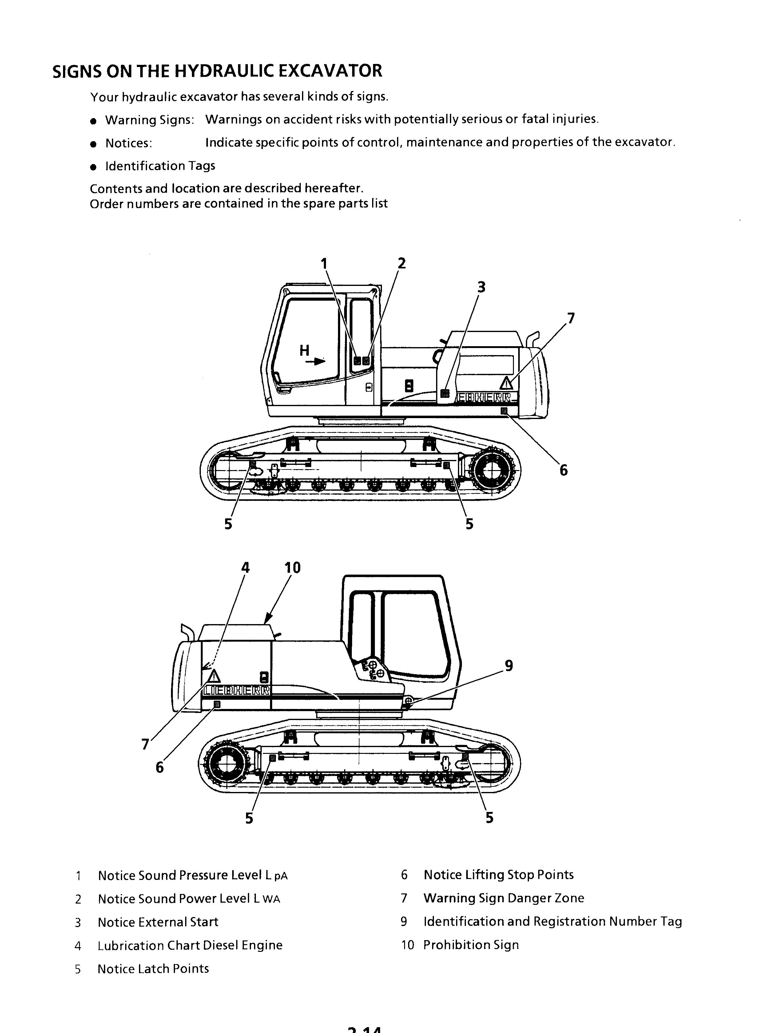
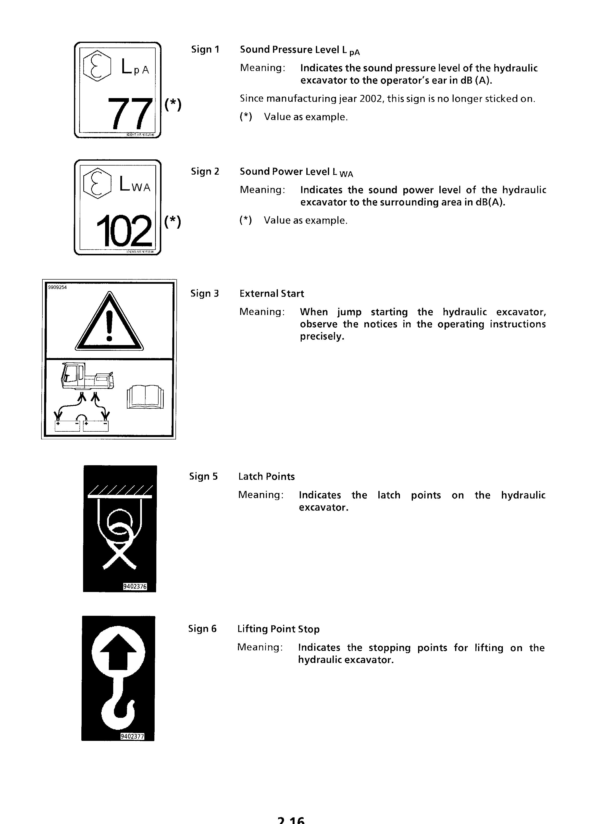
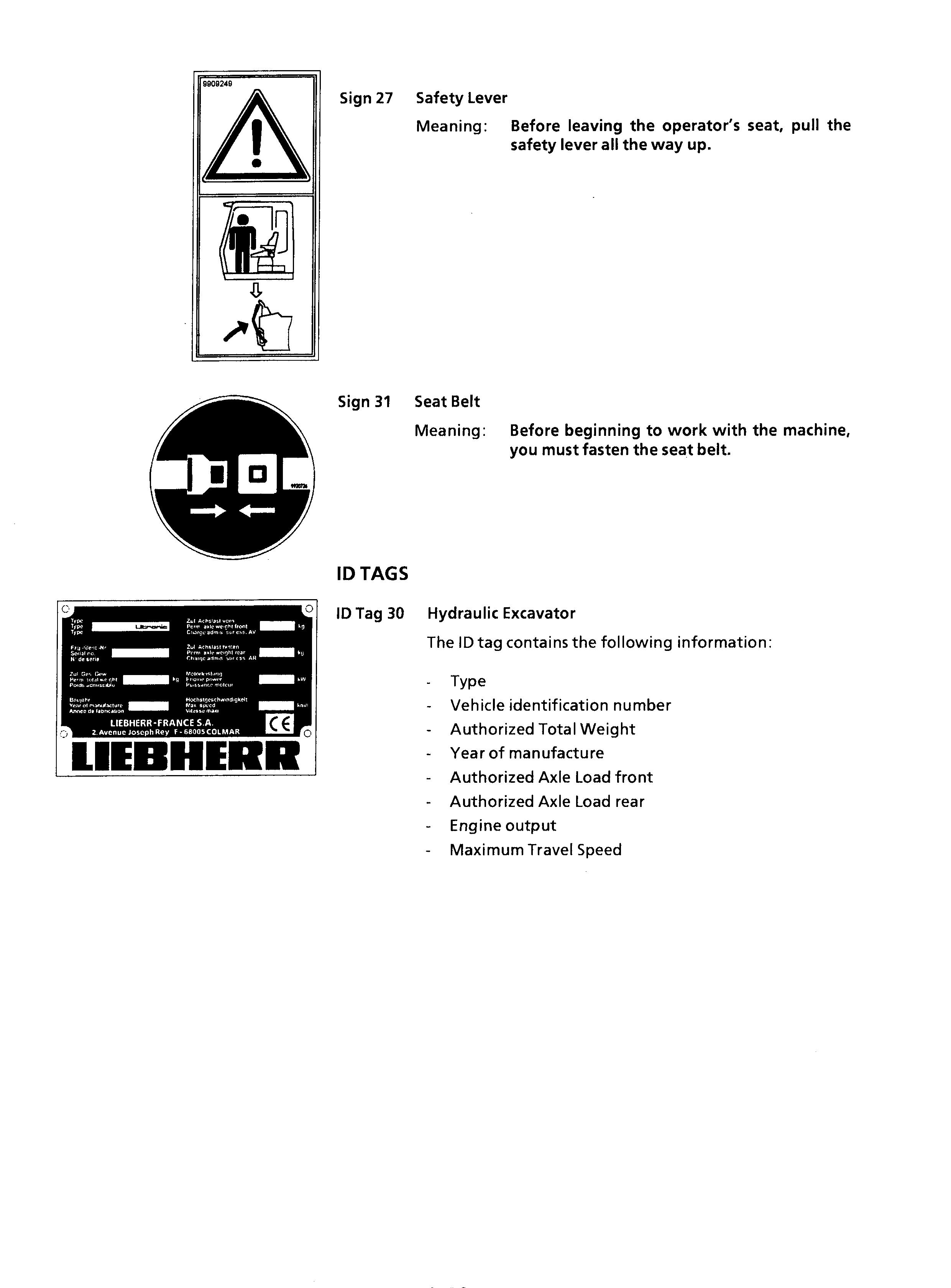
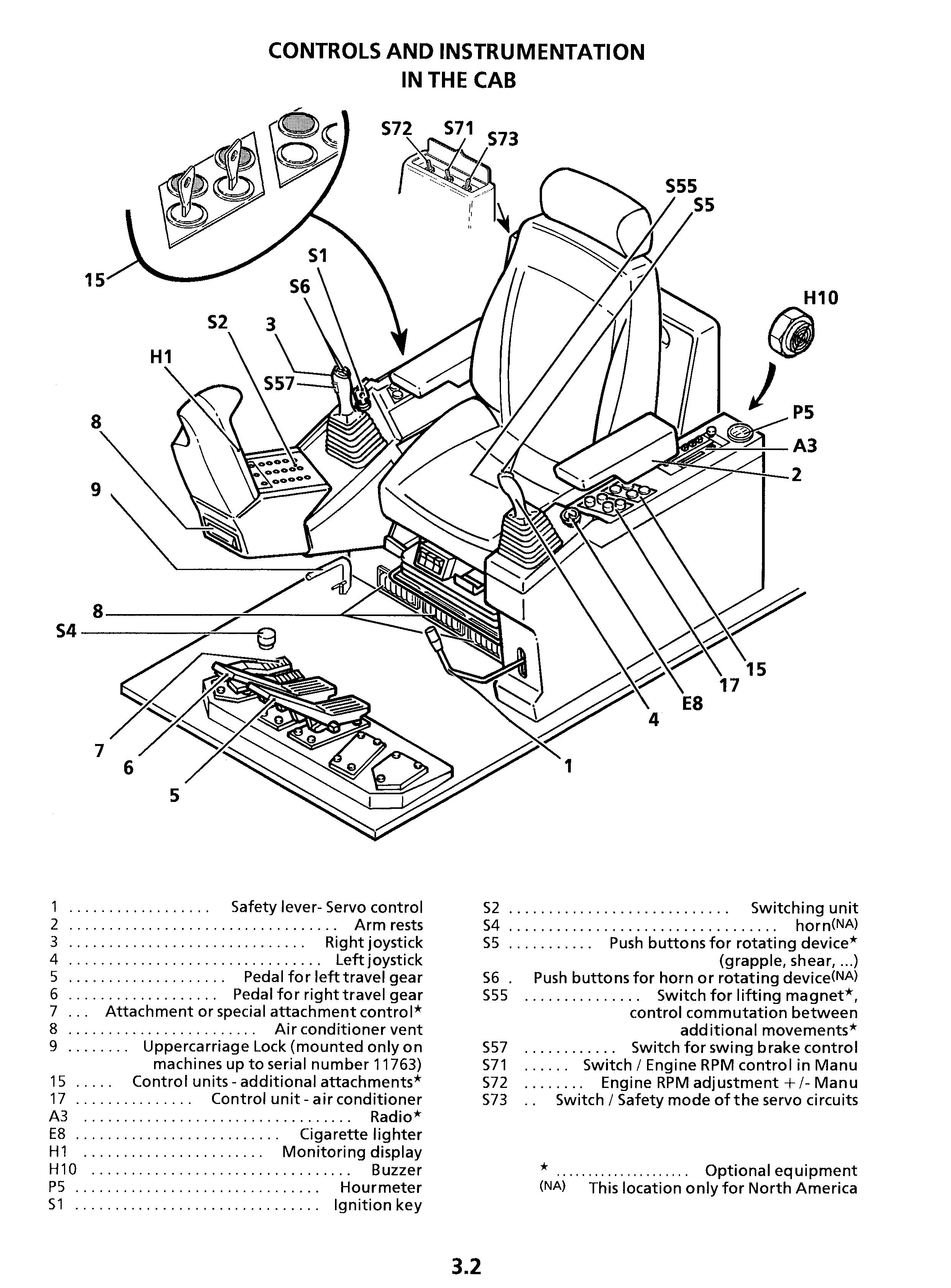
General Safety Information
Study the Operation and Maintenance Manual before operating or working on the excavator. Make sure that you have additional information for special attachments of your machine, read it and understand it!
Allow only authorized personnel informed about the safety rules to operate, service or repair the excavator. Make sure to observe any minimum applicable age requirement.
Allow only properly trained personnel to operate or work on the excavator, make sure to clearly specify the person who is responsible for set up, maintenance and repairs.
Make sure the operator knows his responsibility regarding the observance of traffic regulations and permit him to refuse any unsafe instructions given by a third person.
Any persons still in training should only operate or work on the machine under the supervision and guidance of an experienced person.
Check and observe any person working or operating the excavator periodically and regularly, if they observe safety instructions and guidelines given in the Operation and Maintenance Manual.
Wear proper work clothing when operating or working on the excavator. Rings, watches, bracelets and loose clothing such as ties, scarves, unbuttoned or unzipped shirts and jackets are dangerous and could cause injury!
Wear proper safety equipment, such as safety glasses, safety shoes, hard hats, work gloves, reflector vests and ear protection. Consult your employer or supervisor for specific safety equipment requirements and safety regulations on the job site.
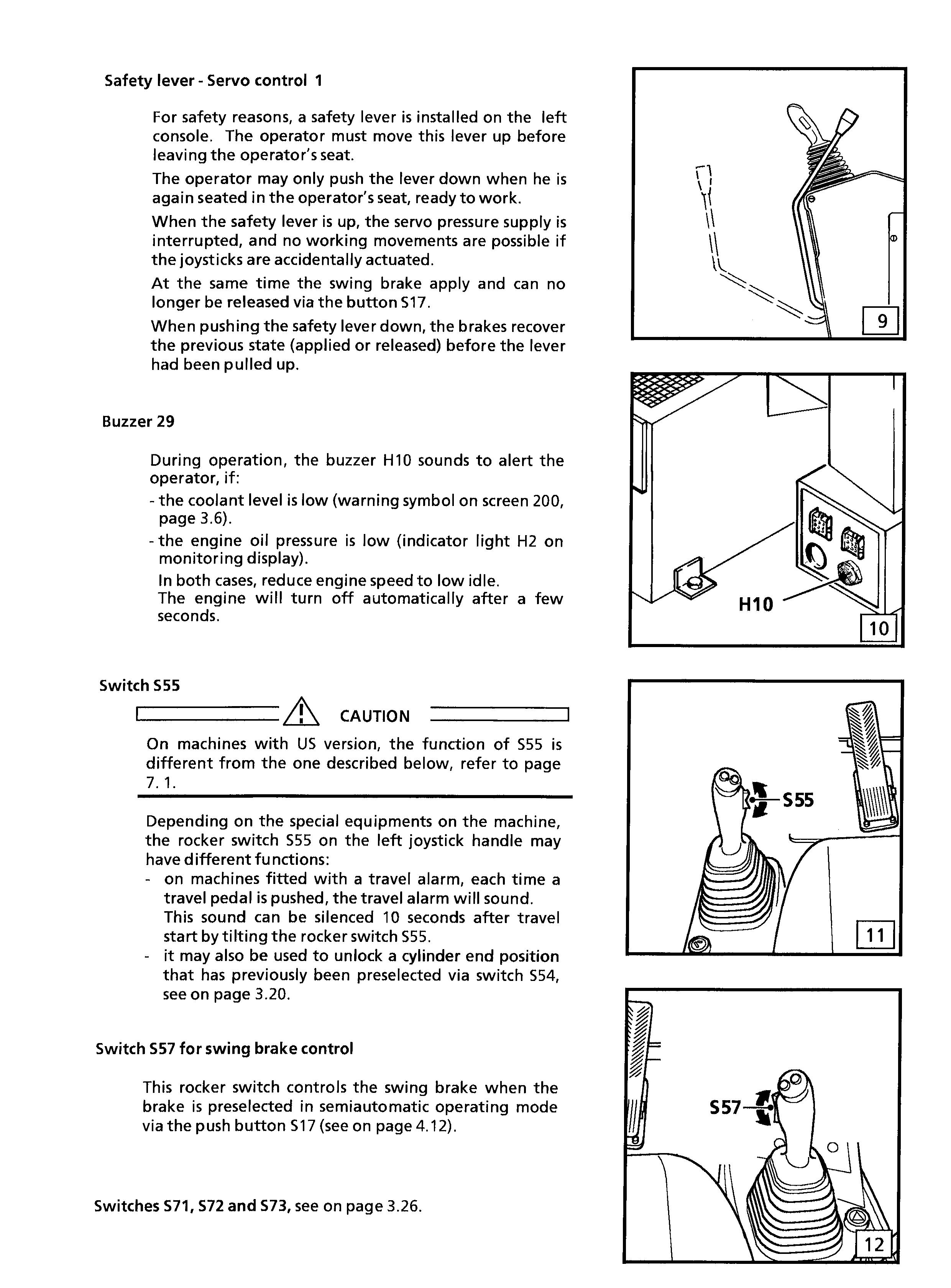
Always tilt up the safety lever before leaving the
Do not carry tools, replacement parts or other supplies while climbing on or off the excavator. Never use the steering column, control levers or joysticks as handholds.
Never jump off the excavator, climb on and off the excavator using only the steps, rails and handles provided.
When climbing on or off the excavator, use both hands for support and face the machine. If needed, use the front window as an escape hatch.
If no other guidelines are given, perform maintenance and repairs utilizing the following precautions :
Park excavator on firm and level ground. Rest the attachment on the ground. Place all control in neutral position and raise the safety lever.
Turn the engine off and remove the ignition key. Before working on the hydraulic circuit, move all joysticks and pedals with the ignition key in contact position and the safety lever tilted down to relieve the servo pressure and the remaining pressures in the different main circuits. In addition, relieve the pressure in the hydraulic tank as described in the Operation and Maintenance Manual.
Secure all loose parts on the excavator.
Never operate the excavator without a complete walk around inspection. Check if all warning decals are on the machine and if they are all legible.
Observe all danger and safety guidelines.
For certain special applications, the excavator must be equipped with specific safety equipment. Use the excavator only, if they are installed and functioning properly.
Never perform any changes, additions or modifications on the machine, which could influence the safety, without obtaining the written permission from the manufacturer. This also applies to the installation and adjustment of safety devices and safety valves as well as to any welding on load carrying parts.
It is forbidden to repair the cab.
Do not install any equipment or attachments made by other manufacturers or any which are not specifically authorized by LIEBHERR for installation without first obtaining the written permission from LIEBHERR. LIEBHERR will issue any required technical documentation for approved installations. Should the electrical circuit be modified or additional components be installed, so the modification must be performed according to the national standards and safety regulations (such as OSHA per the USA). The installation must be certificated by an approved organization and a copy of the certification has to be sent to the LIEBHERR company.
Crushing And Burn Prevention
Never work underneath the excavator unless it is safely resting on the ground and / or is properly blocked and supported.
Never use damaged or insufficient wire ropes, slings or chains. Always wear gloves when handling wire ropes.
Never reach into bores during attachment installation or removal. Never align bores with your fingers or hands. Use proper alignment tools when installing, changing or servicing attachments by qualified mechanics
Keep objects away from the radiator fan. Rotating fans will swirl and throw out objects, which can become very dangerous and cause severe injury to yourself and others.
Avoid contact with any components containing coolant.
At or near operating temperature, the engine coolant is hot and under pressure and could cause severe burns.
Check the coolant level only after the radiator cap is cool enough to touch. Remove the radiator cap slowly to relieve pressure .
Do not allow your skin to come into contact with hot oil or components containing hot oil. At or near operating temperature, engine and hydraulic oil is hot and can be under pressure.
Always wear safety glasses and protective gloves when handling batteries. Keep sparks or open flames away!
Never permit anyone to hand guide the bucket or grapple into position.
When working in the engine area, make sure the top covers and side doors are properly secured or closed with the appropriate supports.
Never work underneath or on the excavator unless it is properly blocked and supported.
Fire And Explosion Prevention
Always turn off the engine while refuelling the excavator.
Never smoke or allow an open flame in refuelling areas or where batteries are being charged, or where batteries or flammable materials are stored.
Never leave machine unattended while fuelling. During this operation, no one but the employee in charge of refuelling is allowed to stay on the excavator.
Always start the engine as described in the Operation and Maintenance Manual.
Check the electrical system regularly and frequently.
All defects, such as loose connections, burnt out fuses and bulbs, burnt or damaged cables must be repaired immediately by a licensed electrician or specially trained personnel.
Never store flammable fluids on the machine except operation.
Inspect all components, lines, tubes and hoses for oil and fuel leaks and / or damage. Replace or repair any damaged components immediately.
Any oil, which escapes from leaks, can easily cause a fire.
Be certain that all clamps, guards and heat shields are installed. These components prevent vibration, rubbing, chafing and heat build-up. Install tie wraps to fasten hoses and wires, as required.
Cold start ether is extremely flammable. Do not use together with preheat. Use ether only in ventilated areas and as directed. Never use it near heat sources or open flames, do not permit anybody to smoke.
Know the location of the excavator's fire extinguisher and be familiar with its operation. Make sure you know your local fire regulations and fire reporting procedures.
A fire extinguisher can be attached inside the operator's cab, using the four threaded holes provided in the rear left support of the cab.
Machine Start Up Safety
Before excavator start up, perform a thorough walk around inspection.
Visually inspect the excavator, look for loose bolts, cracks, wear, any leaks and any evidence of vandalism.
Never start or operate an unsafe excavator. Report all defects to your foreman or supervisor and make sure they are corrected immediately. Make sure all covers and doors are closed and all warning decals are on the machine.
Make sure all windows, as well as inside and outside mirrors are clean, and secure all doors and windows to prevent any unintentional movement.
Be certain that the area surrounding the excavator is free of other personnel, and that no one is working on or under the excavator before starting the engine.
Covers and boxes locks have to be unlocked, to facilitate the fight against fire in case of.
Proceed with the same precaution while climbing up and down the cab, as for the ascension of the machine
Keep ladders, footsteps, handles and handrail in clean condition and always free them from mud, oil, grease, ice, snow or any other obstacles.
To guarantee an easy opening of the cab door in all weather conditions, coat the rubber seals around the door with silicon oil or talcum every two months and more often if necessary. Regularly grease the hinges and lock of the cab door as well the fixing device of the door in opened position.
During maintenance works, always wear safety glasses and proper protective clothes..
To climb up or down the cab, the excavator must be parked on firm, flat and level ground and the uppercarriage must be swung so to align ladders and steps on upper and undercarriage.
Face the excavator when climbing up or down and always hold on to the machine at three points, i. e. keep the contact with the access components at the same time with two hands and one foot or with one hand and the two feet.
As soon as you can reach the handle of the door with your free hand unlock it, and keeping yourself apart from the slewing range of the door, open the door before climbing up any more. Some external influences, and especially the wind, may make the opening of the door uneasy. For this reason, keep and guide the door all the way with your hand and lock it in its opened position, making sure it is securely fixed in this position, so it can not be slammed by the wind.
If the weather conditions are bad, increase your attention to realise climbing or descent from the cab with a maximum of precautions, and do or let do the preliminaries operations of preparation which are necessary so you can move safely.
With those conditions be especially vigilant.
Go on climbing up, always holding yourself by three points, enter the cab and seat down to the seat controls, the inside and outside mirror, the armrests and fasten and adjust the seat belt. Be certain that all controls can be reached comfortably.
If applying fasten the seat belt. Unlock the door using the unlocking lever and close the door holding it by the handle designed for this purpose. Only thereafter lower the safety lever and start the machine.
It is essential to have your seat belt fastened if you want to operate the machine with the cab door opened.
Should the belt be missing on your machine, so you must compulsorily get one installed before you start working with opened cab door.
All noise protection devices on the machine must be functional during operation.
Engine Start Up And Operating Safety
Before start up, check if all indicator lights and instruments are functioning properly, place all controls in neutral position and tilt the safety lever up.
Before starting the engine, alert any nearby personnel that the excavator is being started by sounding the horn.
Start the machine only when seated in the installed).
If you have no other instructions, start the engine as outlined in the Operation and Maintenance Manual.
Tilt the safety lever down and check all indicators, gauges, warning devices and controls for their proper indication.
Start and operate the engine only in a well ventilated area. If necessary, open doors and windows.
Warm up the engine and hydraulic system to operating temperatures. Low engine and hydraulic oil temperatures can cause the excavator to be unresponsive.
Check that all attachment functions are operating properly.
Move the excavator slowly into an open area and check all travel functions for their proper operation, check travel and swing brakes, the steering function as well as the turn signals and lights.
Machine Operating Safety
Familiarize yourself with job site rules. Be informed about traffic and hand signals and safety signs. Ask who is responsible for signalling. Check your surrounding for any obstacles in the working and movement range, check the load carrying capacity of the terrain, and secure the job site to shield it from any public highway traffic. Rope off the working area of the machine and install the necessary signs to forbid any non authorized person entering the area. Always keep a safe distance from overhangs, walls, drop offs, and unstable ground.
Be alert of changing weather conditions, bad or insufficient visibility and of changing ground conditions.
Be alert for utility lines, check the location of underground cables, gas and water lines, and work especially careful in that vicinity. If necessary and/ or if required, call local authorities to mark the location, and take precaution against contact with underground utilities.
Keep sufficient distance to electrical lines. When working in the vicinity of high voltage electrical lines, keep proper distance to assure that the attachment does not come close to the lines. DANGER! You must inform yourself about safe distances. still moving.
Preferably have the electrical lines de-energized (and lockout / tagged out according to the regulations applicable on the job-site) each time it is possible, and in any case if the closeness of the working area make it necessary.
In case you do touch a high voltage line by accident, proceed as follows: do not leave the machine, move the machine, if possible, from the danger zone until you obtain sufficient distance, warn any personnel in the vicinity not to come close to the excavator and not to touch it, instruct or initiate that someone turns off the voltage.
Do not leave the machine until you are absolutely sure that voltage in the line, which had been touched or damaged, has been turned off!
Before moving the machine, make sure that the attachments and equipment is secured properly to avoid accidents.
When travelling on public roads, make sure to observe traffic regulations, and make sure that the machine meets federal and local public highway standards.
Always turn on the lights if visibility is bad or if you are still working during dusk.
Never allow other personnel on the excavator. Operate the excavator only while seated and with the seat belt fastened, if installed.
Report any problems or needed repairs to your foreman or supervisor and make sure they are corrected immediately.
Do not move the excavator until you are certain that no one is endangered by moving the excavator. On machines without negative brakes check the brake system before starting to work, as outlined in the Operation and Maintenance Manual.
Never leave the machine unattended (within view of machine), with the engine running.
When moving the excavator, keep the uppercarriage in lengthwise direction and keep the load as close as possible to the ground.
Prevent any working movements, which could tip the machine over. If the excavator begins to tip or slip on a grade, immediately lower the attachment and load to the ground and turn the excavator facing downhill.
If possible, always operate the excavator with the attachment positioned uphill or downhill, never sideways.
Always travel slowly on rough or slippery ground and on slopes, and on loose soils. Always travel downhill at permissible speed, so engine must run at nominal speed, use only the foot pedals to brake and slow down the machine. Never shift during down hill travel, always shift to a lower gear before travelling downhill. Load an occupied truck only if all safety requirements are fulfilled, notably in order to protect the truck operator.
For demolition work, clearing, crane operation, etc. always use the appropriate protection device designed for this specific application.
If operating in visually obstructed terrain or whenever necessary, have another person guide you. Always have only one person signal you. Allow only experienced persons to attach loads or to guide operators. The guide must be visible by the operator and / or must be in voice contact with him.
Depending on the attachment combination, it is possible for the bucket teeth to hit the cab, the cab protection or the boom cylinders. Be very careful when the bucket teeth get in this range to prevent any damage.
In case of a thunderstorm : lower the attachment to the ground and if possible anchor the digging tool into the soil. leave the cab and move away from the machine before the storm breaks out. Otherwise, you must stop the excavator, turn off the radio and keep inside the closed cab until the end of the storm.
Auxiliary control units can have various functions. Always check their functions when starting up the machine.
Stop the swinging motion of the uppercarriage when lowering the attachment into a ditch without striking the attachment on the ditch walls. Inspect the machine for damage if the attachment has been swung into a wall or any other obstacles.
Applications in which the attachment is to be used to strike the material being extracted are not permitted, even when working in a longitudinal direction.
Repeated strikes against an object leads to damage to the steel structures and machine components.
Please refer to your LIEBHERR dealer if special teeth for heavy-duty or special applications are required.
Do not attach too large bucket or bucket with side cutters or that are during operations with rocky material. This would prolong the work cycles and may lead to damage to the bucket as well as further machine components.
With the 2x45° offset articulation, the offset position may only be employed if the working tool or the attachment does not touch the material.
Operation of the offset articulation to drill into the material is not permitted.
Do not lift the machine during operation. Should this happen, lower the machine slowly back to the ground.
Do not let the machine fall heavily on the ground and do not hold it back with the hydraulics. This would damage the machine.
During operation with the attachment it is forbidden to raise the machine with the dozing blade (e.g. carving at the ceiling when tunnelling).
The hydraulic hammer must be selected with particular care. When using a hydraulic hammer not permitted by LIEBHERR, steel structures or the other machine components can become damaged. Before beginning breaking tasks, position the machine on firm and level ground.
Use a hydraulic hammer designed exclusively for breaking stone, concrete and other breakable materials.
Only operate the hydraulic hammer in the longitudinal direction of the machine and with the windshield closed or with a front protective grid. Ensure during hammer operation that no cylinder is entirely extended or retracted and that the stick is not in the vertical position.
In order to avoid damages to the machine, try not to break stone or concrete while performing retraction and extension motions of the hydraulic hammer. Do not apply the hydraulic hammer uninterrupted for more than 15 secs. at a time to the same place. Change the breaking point. Too long uninterrupted operation of the hydraulic hammer leads to an unnecessary overheating of the hydraulic oil.
Do not use the drop force of the hydraulic hammer to break stone or other materials. Do not move obstacles with the hydraulic hammer. Misuse of this nature would damage both the hammer and the machine.
Do not use the hydraulic hammer to lift objects.
Machine Parking Safety
Park the excavator only on firm and level ground. If it becomes necessary to park the machine on a grade, properly block and secure it with wedges. Lock the uppercarriage with the lock pin (if lock pin is installed).
Lower the attachments to the ground and anchor the bucket lightly in the ground.
Bring all operating levers in neutral position and engage the travel and swing brakes.
Turn the engine off as outlined in the Operation and Maintenance Manual and raise the safety lever before you leave the operator's seat.
Proceed with the same precaution while climbing up and down the cab, as for the ascension of the machine
Before climbing down the cab, you must make sure the machine is parked on a flat, firm and level ground and the ladders and steps are aligned on upper and undercarriage.
Then open the cab door and lock it in opened position and make sure it is securely fixed in this position.
Be aware of difficult weather conditions and anticipate their possible consequences. The wind for example could slam the cab door. If necessary unfasten the seat belt.
Carefully begin climbing down, facing the machine and always holding the contact at three points, keeping the contact with the access components at the same time with two hands and one foot or with one hand and the two feet, until you reach the height where you can close the cab door in the best conditions, keeping yourself apart from its slewing range. Unlock the door using the unlocking lever designed for this purpose and close the door guiding it by the handle. If you want so lock the door and take away the key.
Slowly and carefully go down to the floor. Lock the cab, covers and boxes, remove all keys and secure the excavator against vandalism, unauthorized use, and any attractive nuisance.
Machine Transporting Safety
Use only suitable transporting and lifting devices with sufficient capacity.
Park the machine on firm and level ground and block the chains or wheels.
If necessary, remove part of the attachments during transport.
When loading the machine on a flatbed trailer or railroad car, be sure that the loading ramp incline is less than 30° and covered with wooden planks to prevent skidding.
Remove all mud, snow or ice from track components before moving up the ramp.
Before loading, secure the uppercarriage with the undercarriage with the lock pin (if lock pin is installed).
Align the machine with the loading ramp.
Attach the manual control levers to the foot pedals for sensitive control.
Have another person guide and signal the operator. Have blocks or wedges ready to block the machine, if necessary, to prevent the machine from rolling backwards. Be careful to crushing risks when handling and applying these wedges. Keep clear of wheels and do not attempt to chock or block the machine before its complete standstill.
Retract the attachment as far as possible and lower the attachment as close as possible to the loading surface and carefully drive up the ramp and onto the flat bed trailer.
When the excavator is on the trailer, release the uppercarriage lock pin, turn the uppercarriage back and lower the attachment.
If the backhoe attachment is attached, tilt the stick and bucket in and relock the uppercarriage (if lock pin is installed).
Carefully secure the uppercarriage and other parts with chains, wedges and blocks to prevent slipping. Release the hydraulic pressure, remove the ignition key, raise the safety lever, close and lock the cab and close and secure all other doors and leave the machine.
Carefully check out the transport route. Make sure that width, height and weight allowances are within the permitted limits.
Check that there is enough clearance underneath all bridges, underpasses, utility lines, and in tunnels.
During the unloading procedure, proceed with the same care and caution as during the loading procedure. Remove all chains and wedges. Start the engine as outlined in the Operation and Maintenance Manual. Carefully drive off the loading platform. Keep the attachment as close as possible to the ground level. Have another person guide and signal you.
Machine Towing Safety
Observe the correct procedure: check the index in your Operation and Maintenance manual and
Only tow the excavator if absolutely necessary, for example to remove it for repairs from a dangerous job site.
Be sure all towing and pulling devices such as cables, hooks, and couplers are safe and adequate.
Make sure that the cable or the towing rod are strong enough and are routed around the centre of the undercarriage or to the towing hook on the undercarriage, which is designated for this purpose. Be aware that any damage to the machine caused by towing is never covered by the manufacturer's warranty.
Never allow anyone to stand near the cable when pulling or towing the excavator.
Keep the cable tight and free of kinks.
Engage travel slowly, and do not jerk. With a slack cable, the sudden impact of the load being towed could snap and break.
Keep personnel out of area. If cable breaks while under stress, it could cause severe injury.
During the towing procedure, keep within the required transport position, permissible speed and distance.
After the towing procedure is completed, return the machine to its previous state.
Proceed as outlined in the Operation and Maintenance Manual when putting the excavator back in service.
Machine Maintenance Safety
The machine may not be made unsafe when performing maintenance work. Never attempt maintenance procedures or repairs you do not understand.
for service and maintenance intervals. Make sure you use only appropriate tools for all maintenance work.
Refer to your Operat Manual to see, who is authorized to perform certain repairs. The operator should only perform the daily / weekly maintenance procedures.
The remaining work may only be performed by especially trained personnel.
Use only replacement parts corresponding to the technical requirements specified by the manufacturer. This is assured by using only original Liebherr replacement parts.
Always wear proper work clothing when maintaining the excavator. Certain work may only be performed with a hard hat, safety shoes, safety glasses and gloves.
During maintenance, do not allow unauthorized personnel to enter the maintenance area.
Secure the maintenance area, as necessary.
Inform the operator before any special or maintenance work. Make sure he knows the person, who is in charge of the work.
If not otherwise noted in the Operation and Maintenance Manual, always make sure the excavator is parked on firm an level ground and the engine is turned off.
During maintenance and service work, make sure you always retighten any loosened screw connections!
If it is necessary to disconnect or remove any safety devices during set up, maintenance or repair, make sure that after completion of repairs, the safety devices are reinstalled and checked for proper function.
Before any maintenance work and especially when Remove the ignition key.
After end of maintenance works or repair, restart the machine according to the instructions "Machine start up", in this manual.
Before any repairs or maintenance work, clean any oil, fuel and / or cleaning substances from any fittings and connections . cloths.
Use only non-flammable cleaning fluids to clean the machine.
Any welding, torch or grinding work on the machine must be explicitly authorized. Written authorization is necessary for welding on carrying structures. Before any using a welder, torch or grinder, clean off any dust and dirt and remove any flammable materials from the surrounding area. Make sure the area is sufficiently ventilated. Danger of Fire and Explosion!
Before cleaning the machine with water or steam (high pressure cleaning) or other cleaning fluids, make sure that all openings, which , for safety and/ or functioning reasons should not be exposed to water / steam/ cleaners, are covered and / or masked off. Especially sensitive are electrical motors, control boxes and plug connectors.
Make sure that the temperature sensors of the fire alarm and extinguishers system do not come in contact with the hot cleaning fluids, which could trigger the fire extinguishing system. Remove all coverings and masking material after completing the cleaning procedure. Then check all fuel lines, engine oil lines and hydraulic oil lines for leaks, loose connections, chafing and / or damage. Fix any problems immediately.
If you use a high pressure cleaner with steam or hot water to clean the machine, observe following recommendations : the distance between the nozzle and the surface to be cleaned must be no lower than 20 inches the water temperature should not exceed 60°c (140°F) limit the water pressure to 80 bar maximum (11500 PSI) if you employ cleaning fluid, only use neutral cleaning agents such as customary car shampoos diluted to 2 or 3 percent maximum
Never employ high pressure cleaning apparatus during the two first months following machine delivery or repainting.
Observe all product safety guidelines when handling oils, grease, and other chemical substances.
Make sure service fluids and replacement parts are disposed of properly and in an environmentally sound manner.
When using hot service fluids, be very careful. (They can cause severe burns and injury!).
Operate combustion motors and fuel operated heaters only in well ventilated areas. Before operating these units, check ventilation. In addition, always follow applicable local regulations.
Never try to lift heavy parts. Use appropriate lifting devices with sufficient load carrying capacity. When replacing or repairing parts or components, make sure they are mounted very carefully on lifting devices, to prevent any possible danger. Use only suitable and technically sound lifting devices, make sure that lifting tackle, wire cables, etc. has adequate load carrying capacity. Never position yourself, walk or work underneath suspended loads.
Never use damaged lifting devices, or devices which are not sufficient to carry the load. Always wear gloves when handling wire cables.
Ask only experienced personnel to attach loads and guide and signal the crane operator. The guide must be within the visibility range of the operator and / or must be in direct voice contact with the operator.
When working overhead, use appropriate and safe ladders, scaffolding or other working platforms designated for that purpose. Never step on parts or components on the machine when maintaining or repairing items overhead. When working high above ground, make sure you are fitted with ropes and appropriate safety devices which will prevent a possible fall. Always keep handles, steps, railings, platforms and ladders free of dirt, snow and ice!
When working on the attachments, for example when replacing the bucket teeth, makes sure the attachment is supported properly. Never use metal on metal support!
For safety reasons, never open and remove a track chain unless having previously totally released the pretension of the chain tensioning unit.
Never work underneath the machine if it is raised or propped up with the attachment. The undercarriage must be supported with wooden blocks and supports.
Always support the raised machine in such a way that any shifting to the weight change will not influence the stability. Do not support the machine with metal on metal support.
Only qualified, especially trained personnel may work on travel gear, brake and steering systems. If it becomes necessary that the machine must be repaired on a grade, block the chains with wedges and secure the uppercarriage to the undercarriage with the lock pin.
Only qualified, especially trained personnel may work on the hydraulic system.
Never check for leaks with your bare hands, always wear gloves. Fluid escaping from a small hole can have enough force to penetrate the skin.
Never loosen or remove lines or fittings before the attachment has been lowered to the ground and the engine has been turned off. Then turn the ignition key to contact position with tilted down safety lever, move all servo controls (joysticks and foot pedals) in both direction to release pressures. Then release the tank pressure as outlined in this Operation and Maintenance Manual.
Always disconnect the battery cable before working on the electrical system or before any arc welding on the machine. Always disconnect the negative (-) cable first and reconnect it last.
Check the electrical system regularly. Make sure that any problems, such as loose connections, burnt out fuses and bulbs, scorched or chafed cables are fixed immediately by an electrician or qualified personnel.
Use only Original fuses with the specified amperage. Never use a different size or stronger fuse than the original fuse.
On machines with electrical medium or high voltage systems:
If there is any problem with the electrical energy supply, turn the machine off immediately.
Follow established lockout / tag out procedures where applicable.
Any work on the electrical system may only be performed by a qualified electrician or qualified personnel under the guidance and supervision of an electrician, according to electro - technical regulations.
If any work is required on any parts which carry current, use a second person to turn off the main battery switch, if necessary. Rope the work area off with a safety rope or chain, and set up warning signs. Use only insulated tools.
When working on medium and high voltage components, shut off the voltage and connect the supply cable to the ground and ground the components, such as the condenser, with a grounding rod.
Check all disconnected parts if they are truly free of current, ground them and close them off quickly. Insulate any close-by, current carrying parts.
Hydraulic Lines And Hoses
Hydraulic lines and hoses may never be repaired!
All hoses, lines and fittings must be checked daily, but at least every 2 weeks for leaks and any externally visible damage! Never check for leaks with your bare hands, use a sheet of paper or something else. Any damaged sections must be replaced immediately! Escaping oil can cause injuries and fires!
Even if hoses and lines are stored and used properly, they undergo a natural aging process. For that reason, their service life is limited. Improper storage, mechanical damage and improper use are the most frequent causes of hose failures. Concerning the hoses, you must follow the safety regulations applicable to your work environment and job site and any federal, state and local safety requirements.
Using hoses and lines close to the limit ranges of permitted use can shorten the service life (for example at high temperatures, frequent working cycles, extremely high impulse frequencies, multi shift or around the clock operations).
Hoses and lines must be replaced if any of the following points are found during an inspection (see guidelines ISO 8331):
Damage on the external layer into the inner layer (such as chaffing, cuts and rips); Brittleness of the outer layer (crack formation of the hose material);
Changes in shape, which differ from the natural shape of the hose or line, when under pressure or when not under pressure, or in bends or curves, such as separation of layers, blister or bubble formation, crushing or pliers.
Leaks;
Non observance of installation requirements; Damage or deformation of hose fittings, which might reduce the strength of the fitting or the connection between hose and fitting; Any movement of hose away from the fitting; Corrosion on fittings, which might reduce the function or the strength of the fitting; When replacing hoses or lines, always use Original replacement parts.
Route or install the hoses and lines properly. Do not mix up the connections!
Always take care to avoid torsional strain when installing a new hose. On high pressure hydraulic hoses, the mounting screws must be first mounted on both hose ends (full flange or half clamp) and tightened only thereafter.
On high pressure hoses having one curved end, always tighten first the screws on the curved hose end and only then the screws on the straight hose end.
Install and tighten the hose clips that may be mounted on the hose middle only when the both hose ends are already tightened.
Always install hoses so to avoid any friction with other hoses and parts.
We recommend to keep a distance between hose and other parts of at least one half of the hose outer diameter. Keep a minimum gap of 1/2 inch in any case.
After mounting a hose connecting two parts that are movable to each other, check during the return to service that the hose is not rubbing in the whole moving range.
Check daily that all flanges and covers are fixed correctly. It will prevent vibrations and damage during operation.
Protection Against Vibration
Stress caused by vibration in mobile construction machinery is predominantly a result of the way in which it is operated. The following parameters have a particularly significant influence: can be reduced by noting the following recommendations:
Terrain conditions: Unevenness and potholes; Operational technique: Speed, steering, elements during travel and during operation. The machine operators themselves are largely responsible for the actual stress caused by vibration as the operators determine speed, gear transmission, manner of handling and travel routes.
Thus, a wide range of different forms of vibrational stress are resulted for the same machine type.
Select the correct machine, equipment and accessories for each respective application. Use a machine which features a suitable seat (thus, for earthmoving machines, e.g. hydraulic excavators, a seat which complies with EN ISO 7096).
Ensure that the seat remains in good condition and adjust the seat as follows:
1. Adjustment of the seat, and thus the vibrations being produced from the seat, should be carried out in relation to the weight and size of the operator
2. Check the vibration absorption and adjustment mechanisms of the seat regularly and ensure that condition of the seat always adheres to the specifications of the seat manufacturer.
Check the maintenance condition of the machine, in particular: tyre pressure, brakes, steering, mechanical connections, etc.
Do not carry out steering, braking, acceleration and switching, or move working attachment, in jerky movements.
Adapt the machine speed to the travel path to reduce vibrational stress:
Reduce the speed when negotiating rough terrain;
Travel around obstacles and avoid very rough terrain whenever possible.
Ensure that the terrain over which the machine is being driven or operated is well maintained: Remove large stones and obstacles; Fill in ditches and holes;
Ensure that machines are on-hand for the preparation and upkeep of practical terrain conditions and that sufficient time for this work is allowed for.
Travel over longer distances (e.g. on public roads) with adequate (average) speed.
For machines which are used primarily for travelling, use special auxiliary systems for the journeys (wherever available), allowing a vibration reduction for this application type.
Should these auxiliary systems not be available, regulate the speed so that a "vibrational build-up" of the machine is avoided.

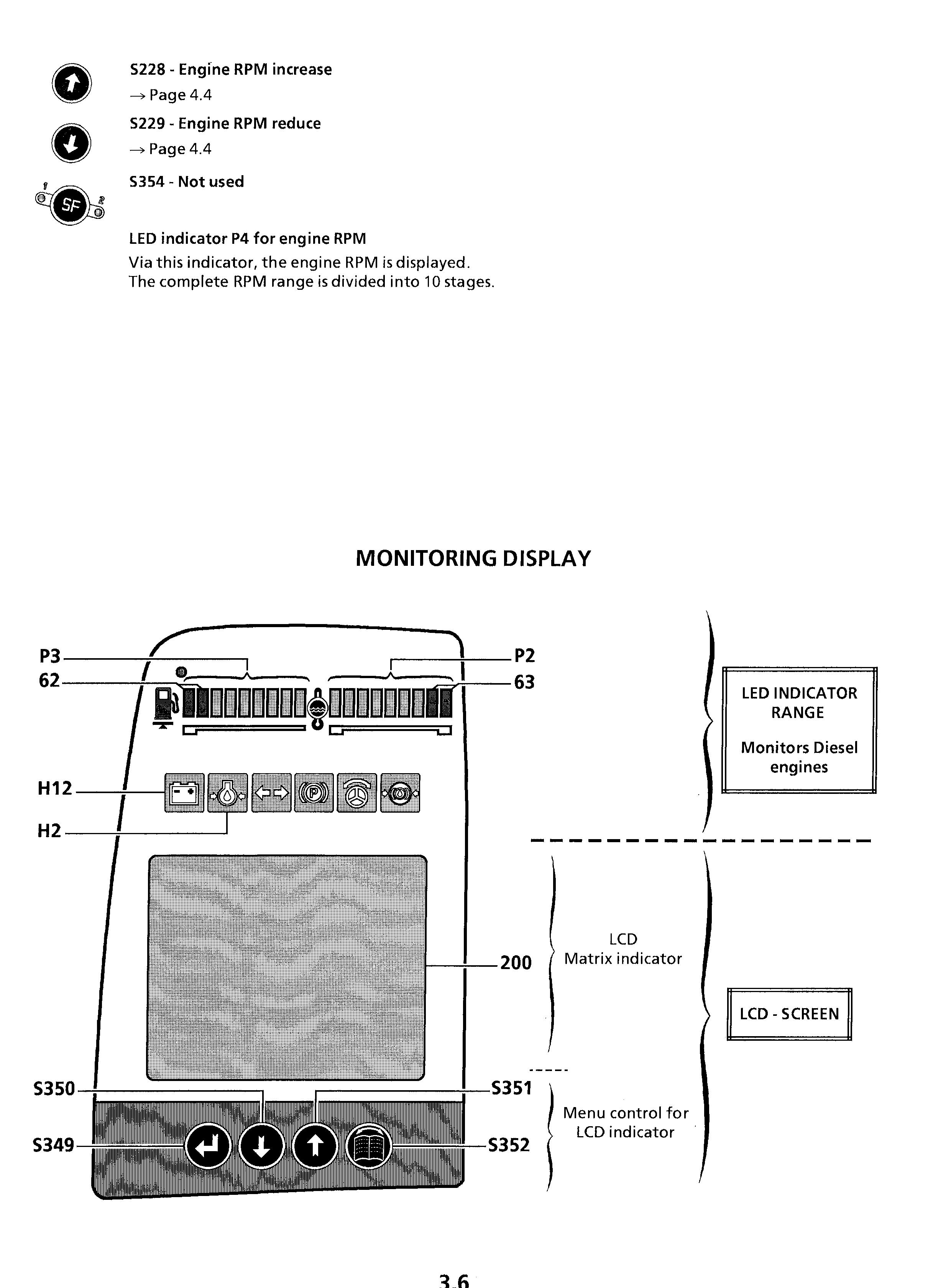
Led Indicator Range
Indicator light H2 - low engine oil pressure
If the engine oil pressure drops during operation below a preset value, which depends on the momentary Diesel engine RPM, the indicator light H2 lights up after 2 seconds.
At the same time, the buzzer will sound to alert the operator that the oil pressure is too low.
Return the engine immediately to low idle
Charge indicator light H12
Indicator light H12 lights up if the starter key is moved to contact position and turns off as soon as the engine starts. During operation, this indicator light lights up if the alternator V-belt or the electrical charge system is defective.
Turn the engine off and correct the problem.
Engine coolant temperature gauge P2
During operation, the indication must remain in the green range.
If the engine coolant overheats (coolant is above 100°C = 212°F), the red LED indicator light 63 starts to light up on the right end of the indicator.
Simultaneously, the buzzer will sound in the cab and the warning signal E503 will appear on the LCD screen
The engine power is reduced and the working pumps return automatically to minimum flow at the same time. Stop working soon and keep the engine running at high idle.
If the default persists for over 60 seconds, lower the engine RPM to low idle and turn the engine off after 3 -5 minutes.
Locate the reason for the trouble and get it repaired.
Fuel gauge P3
The LED indicator lights show the fuel level.
When the both red LED 62 light up, about 10% to 20% fuel are left in the tank as reserves.
Lcd Schirm
Adjust the contrast on the LCD screen or "DOWN" key. The new setting will be stored in the system. To retrieve the original contrast setting, depress the both arrow keys "UP" and "DOWN" at the same time during system start (when all the light diodes are on).
Adjust the background lighting on the LCD screen and the "UP" or "DOWN" key. The new setting will be stored in the system. A light sensor on the upper left hand side of the display controls the LCD lighting, depending on the ambient light conditions.
The follow up control by the light sensor is performed around the basic setting adjusted via the keys. If the ambient light conditions are low, the background lighting will be reduced accordingly.
LCD screen control keys
The display can be controlled via 4 keys S349 "RETURN", S350 "DOWN", S351 "UP" and S352 "MENU" (see above illustration).
These keys are used to change from the main display to the menu selection and to scroll through various other menus.
Main Screen
The main screen appears after the unit is turned on and remains in place until the "MENU" key is pressed to change to the menu selection..
Main screen view
SY field : The upper field of the monitor shows warning and indicator symbols, up to maximum 4 symbols at the same time.
If more than 4 symbols must be shown, then every 10 seconds, the symbols move to the left by one symbol.
The following list shows all symbols which can appear in this field.
EC field: The EC window displays any applicable error codes for any electrical errors in the excavator electronics, (line errors, sensor errors, ...). Max. 7 error codes can be displayed at the same time . If more than 7 errors occur, an arrow next to the error code window points to additional error codes on the list.
Press the arrow key to move the error code window in the selected direction on the error code list. For detailed error codes list, refer next pages.
INF field: The INF field on the right hand side of the main screen displays temporary information, also in graphic form.
If more than 3 symbols must be shown, then every 10 seconds, the symbols move to the left by one symbol. Displays are shown as graphics or text and inform about specific operating conditions (such as actuated flow reduction, emergency operation of Diesel engine
TI field This field, at the bottom right of the screen displays the main hourmeter and the daily hourmeter of the machine.
During the display start-up phase, the operator will be alerted about a possible upcoming service interval, by a graphic symbol. In this case the hours of this interval are displayed instead of the machine hourmeter (as an example 500 hours on fig. beside).
The recalling of upcoming service interval lights up to about 8 seconds.
The symbol activated for the pumps.
The symbol indicates that no external limitation is activated but an internal flow limitation (travel,
Control of the screen at error recognition:
In case a new error, displayed in field SY, is recognized, the presentation will return to main screen, and the corresponding symbol is displayed. Depending on the default (urgency step), the buzzer will alert acoustically at the same time, either buzzing in continuous or emitting intermittent sounds.
The symbol signals that the buzzer of the control unit is activated. Using the key it is possible to quit the defaults indicated by a continuous buzzing.
Symbols for operating errors displayed in field SY an error appears, the control unit enters the corresponding error code in the stored error statistics.
Low engine coolant level
This symbol appears if the coolant level drops below the minimum level. At the same time the buzzer will sound in the cab.
E 502
Bring the engine to low idle and turn it off after about 5 seconds. Find and repair the coolant loss
Engine coolant overheat
This symbol appears simultaneously with the lightning of the red LED 63 on the engine coolant temperature gauge P2, see on page 3.7.
E 503
Low hydraulic oil level
E 504
This symbol appears if the oil level in the hydraulic tank drops below the minimum level. At the same time the buzzer will sound in the cab. Turn the engine off, find and repair the cause of the oil loss. Add hydraulic oil only via the return filter (see page 5.16).
Hydraulic oil overheating
E 505
E 506
This symbol appears if the hydraulic oil temperature in the tank exceeds 98°C (208°F). Turn the engine off, find and correct the problem (oil cooler dirty, blower or thermostat defective,...).
Splitterbox oil overheating
This symbol appears if the oil temperature in the splitterbox exceeds 100°C (212°F). Turn the engine off, find and correct the problem (splitterbox cooler dirty).
Overvoltage in electrical system
This symbol appears if during operation the system voltage exceeds30 Volts during at least 0,5seconds.
E 511
Error codes charts
Menu
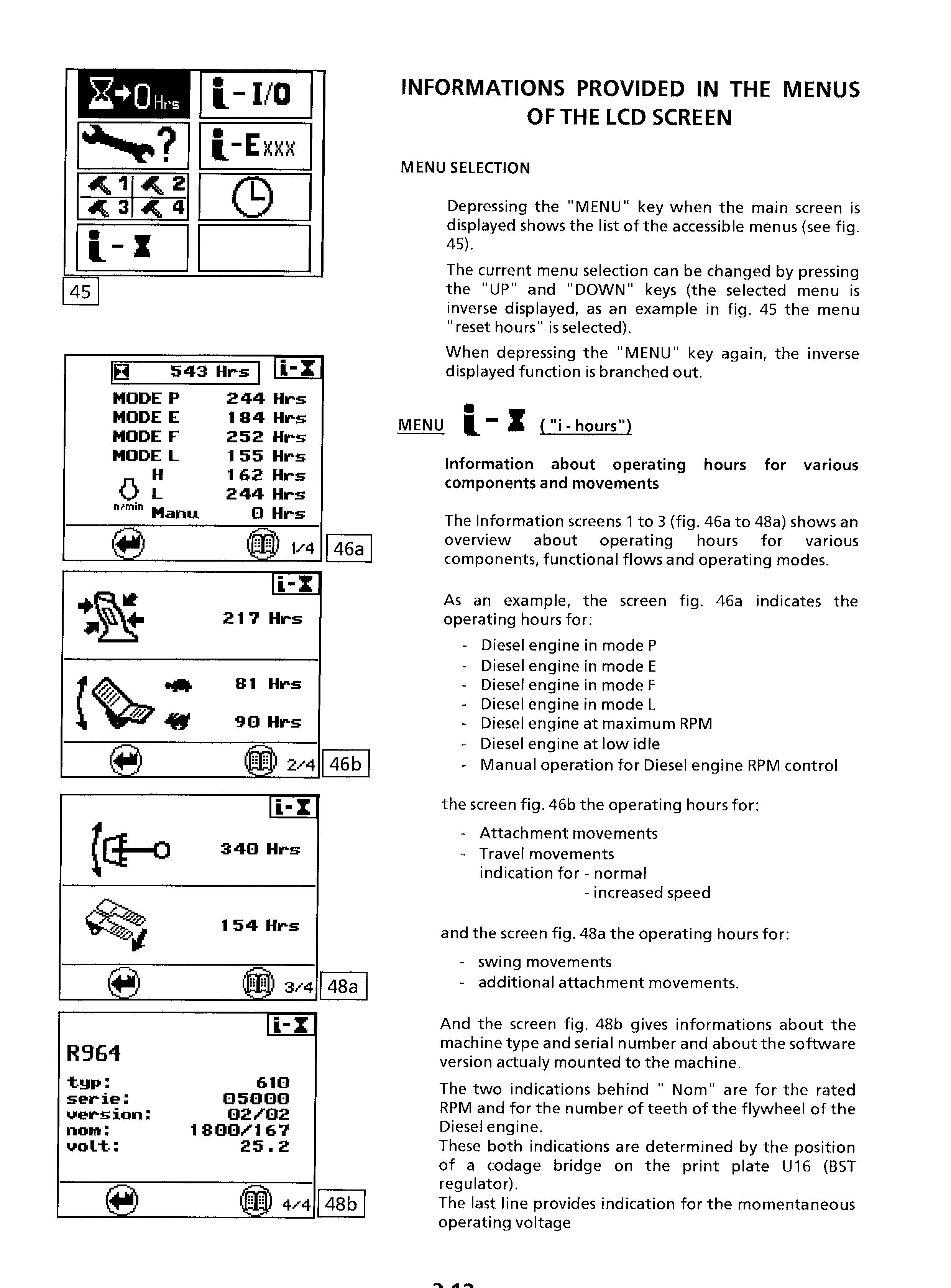
a) INFORMATION ABOUT THE CONTROL OF THE ENGINE RPM (This function is existing since Software Version V2.4). The screen 0/5 appears only on machines on which the engine RPM is adjusted by an hydraulic cylinder via an electronic regulation.
The graphic bar in the lower part of the screen gives the momentary value of the regulation current to the RPM control cylinder.
b) INFORMATION ABOUT THE HYDRAULIC PUMP : information screens 1/5 (50a - 50b) and 2/5 (51)
This screen gives information about the operating position of the hydraulic pumps.
The screen 1/5 gives following indications for each working pump if the flow and pressure limitation is activated, and its percentage. The screen shows for this limitation a graphic bar with electric current value and indicates for the pump the amount of the momentary flow control signal
On figure 50a, an external limitation (Hardware entry I1, option 2) ist activated. With this option, the pump flow and operating pressure are limited to 55% of the maximal value.
In case of an external activation of limitation, the symbol "R" is displayed in the field TI, see main screen.
The figure 50b, two internal limitations (Pressure cut in stage boom and translation M1) are simultaneously activated with the external limitation (Hardware entry I1, option1).
With simultaneously activation of several limitations, the one with the smallest value is decisive for the hydraulic pump. In that case, the symbol "R" is displayed in the field TI.
In case of only one activation of limitation, the symbol "R" turns into " ".
Notice :
For R 904 to R924 machines, the signal of regulation solenoid valve EV1 limits both pumps.
For R 934 to R974 machines, every pump can independently being limited true regulation solenoid valves EV1 and EV2.
For R 984 machines, every pump can independently being limited true regulation solenoid valves EV1, EV2, and EV3. For every machine, the operating pressure is limited true regulation solenoid valve EV6
The internal flow limitation M1 is active during the translation. The internal flow limitation M2 is active by use of pressure cut in stage boom on keyboard .
The internal flow limitation M3 is active while the flap is operated.
The internal limitation SF, by SF-button switched on.
The display 2/5 (51) represents the present current of regulation solenoid valves LR (current value for power regulation).
c) INFORMATION CONCERNING THE COOLER FAN CONTROL SYSTEM information screens
3/5 (52) a) ALLOCATION OF FLOW LIMIT OPTIONS TO EXTERNAL INPUTSI1 (Special attachment input; as an example when operating a hammer pedal)
The screen 3/5 appears only on machines fitted with an electronically regulated cooler fan drive.
The graphic bar in the lower part of the screen gives the momentary value of the current to the regulation solenoid valve EV5 for the fan RPM.
In this menu, pre-defined flow limitations (options) are allocated to the hardware input I1.
The arrow near the symbol gives the actual allocation (Fig. 65a and Fig. 65b).
In example beside, the option 3 is active for the input I1, this means, if the external hardware input I1 is activated, then the nominal pump values allocated in option 3 for the excavator control are given as maximum nominal values.
If another option must be allocated to input I1 (as an example due to a modification of the working attachment), so first select another attachment in the vertical symbol range via the key "UP" or "DOWN", as for example Option 10 in Fig. 65b
Confirm the selected option by pressing the "MENU" key, the new option must then appear in the column.
The right part of the screen provides indication for the currently set pump values corresponding to the option shown in the selection window.
The values EV1 up to EV3 determines the initiated working pump flow limitation while additional attachment operating
Notice : - The pump choice EV2 does not appear for Load Sensing machines R 904 up to R 924.
- The pump choice EV3 appears only for machines provided with 3 separetely adjustable working pumps (R984, Special machines, ...).
The value EV6 determines the permitted maximal pressure level for the additional attachment feeding. The value after "Quota" choice has no importance for crawling excavator.
While choosing an option appears in the lower section of the screen its designation, if it has been defined on option parameterisation. As example on fig.66 appears "HM2000", option designation allocated to the hydraulic hammer.
MENU ("set service") INFORMATION AND CONFIRMATION OF SERVICE INTERVAL
This screen (fig.69) is an information screen and can be used to confirm a completed service interval. The screen shows the operating hour for the next service interval (in example beside ="500 hrs") and the current operating hours ("174 hrs").
An upcoming service interval can be confirmed within max. 50 operating hours before the next service interval. When this time frame is reached, the screen (fig.70) will display a question regarding completion of the service works for this interval.
If the question is answered with "OK" then this menu will be discontinued.
If it is answered with "OK", then the current operating hour will be stored as the last confirmed service interval.
MENU ("reset data") RESET OF THE DAILY HOURMETER
This menu (fig.71) allows to reset to 0 the daily hourmeter.
To reset the daily hourmeter, first select "OK" via the key "UP" or "DOWN", and then confirm this choice by pressing the "MENU" key.
MENU ("set clock")
This menu permits to set the time shown into upper section of the screen.
The selection of this menu is possible only on machines fitted with a display with software versions 2.6 / 5.6 and later.
(since SN 13469 for R914B / since SN 13436 for R924B)
(since SN 12077 for R934B / since SN 13274 for R944B).
After function start, the presently set time will appear in the lower section of the screen with the first digit shown inversely (unity digit of the minutes) ), Fig. 72.
Use the arrow key to modify the inversely displayed position the next higher number (more left digit).
When the highest number has been reached, it will start over with the lowest number the function and to store the set time. on the screen.
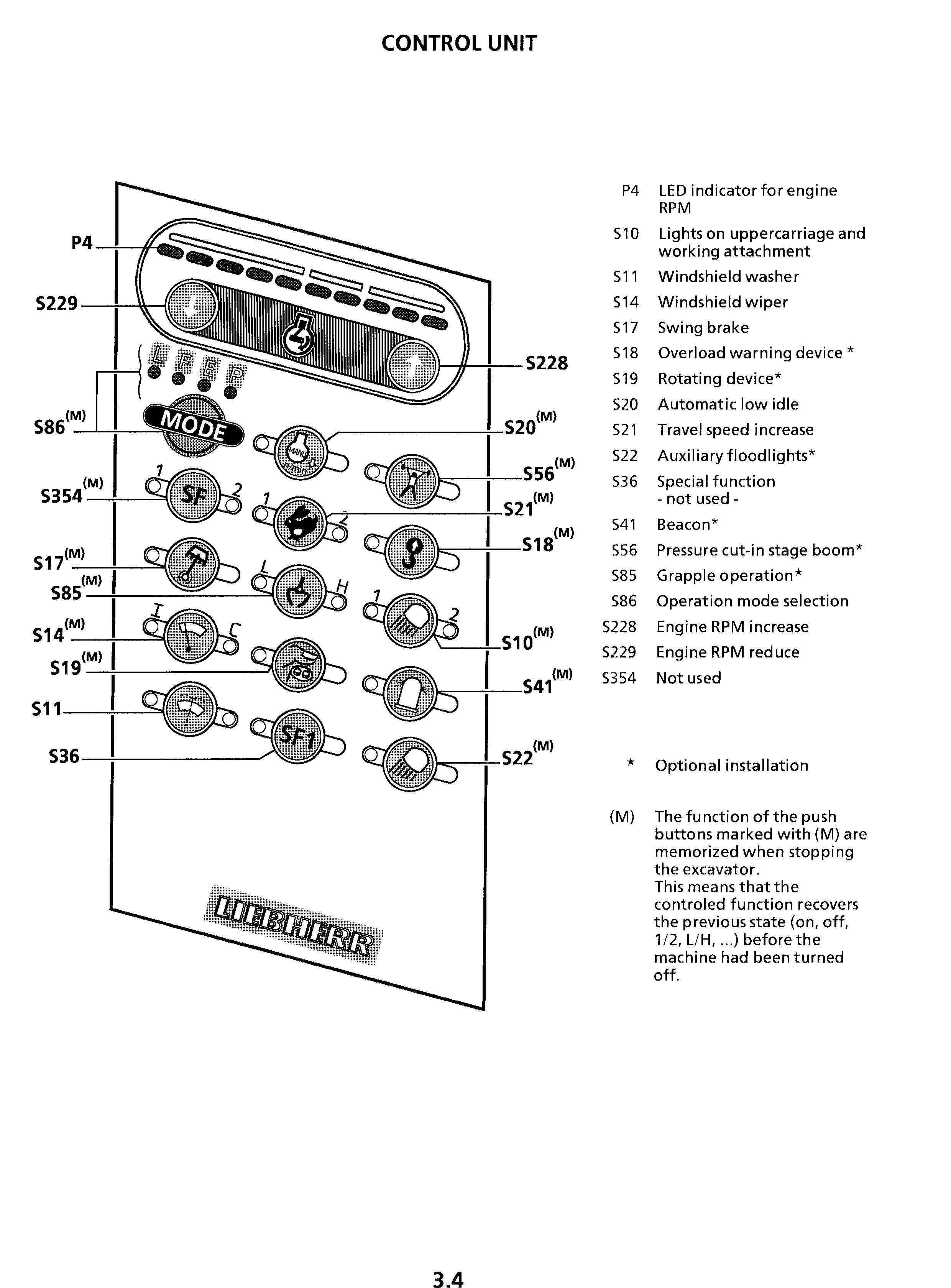
Controls And Instrumentation For Optional Equipments
Right side control desk
H40 Control light / Pre-selection hydraulic circuit
H90 Control light / Rotation in opposite direction of reversible fan
H292 Control light / Special control system
S26 Touch / Fuel preheater
S40 Touch / Frequency commutation for hydraulic hammer
S46 Touch / Lifting magnet
S47 Key switch or touch / Quick disconnecting device
S53 Touch / Special control circuit
S54 Key switch / Unlocking of hydraulic cylinder end position
S74 Code key / Start locking device
S76 Touch / Travel brakes
S77 Touch / Pressurized driver's cab
S79 Touch / Flow divider for special attachment
S84 Push button / Centralized lubrication
S98 Touch / Low pressure protection for boom cylinders
S104 Touch / Width adjustable undercarriage
S114 Rotating switch / Control of special attachments with the rocker switch S55 on joystick
S117 Rotating switch / Pre-selection hydraulic circuit
S160 Push button / Control of reversible fan in opposite direction
S168 Key switch / Oil flow limitation when operating a super long working attachment
S210 Push button / Cold start aid
S218 Touch / Cab roof window wiper
S247 Key switch / Commutation of control system Normalized control / Special control
S275 Touch / Additional floodlight rear of cab roof
S276 Touch / Additional floodlight on counterweight
S357 Touch / Boom height compensation during grapple closing motion
S358 Push button / Cab roof window washer
Left side control desk
S78 Push button / Height adjustable cab - emergency down
S80 Push button / Height adjustable cab - locking device on / off
S200 Push button / Height adjustable cab - up
S201 Push button / Height adjustable cab - down
S232 Control unit S232 / Standstill cab heater
* The location of these controls may differ, depending on the type of the other installed optional equipments..
Control light H40 - Pre-selection hydraulic circuit
This lamp reports pre-selection of a certain consumer via rotating switch S117.
Control light H90 / Rotation in opposite direction of reversible fan
On machines fitted with the special equipment "cooler fan reversible", this control light lights up to indicate that the fan has been changed over to rotation in opposite direction via the push button S160.
Control light H292 - Special control system
This control light lights up to indicate that a special, non standard lever arrangement has been turned on via the key switch S247.
Touch S26 - Fuel pre-heater
This button turns on the installed fuel heating system (Thermoline fuel hose, or heater resistor inside the fuel filter).
The Control light inside the push button shows when the heating system is on.
Touch S40 - Frequency commutation for hydraulic hammer
This touch allows to increase the cycle frequency of an hydraulic hammer.
Touch S46 - Operation with a lifting magnet
This button turns on the generator which supplies the lifting magnet, and also switches on the control circuit of the magnet (push buttons S6 at the top of the right joystick handle, see also page 4. 17). The control light inside the touch lights up when the control circuit is on. In this case, the engine idle automatic is deactivated; the engine RPM is automatically set to a fixed value and can not longer be set using the buttons S228, S229 and S86.
Key switch or touch S47 - Quick change adapter
The switch S47 turns on the control circuit for the quick change adapter for the working tool. The locking pins of the adapter can then be retracted or extended using the both push buttons S5 on the top of the left joystick handle. (Also see on chapter 8.2).
Touch S53 - Special control circuit supply
When this touch is actuated, an additional control circuit for a special equipment is made alive. The green indicator light in the touch lights up to show that the additional servo control circuit is under pressure.
Key switch S54 - Unlocking of cylinder end position
On some special working attachments, or on attachment showing particular cinematic capacities (as example on industrial attachment), certain movement(s) may be stopped automatically by electrical end switches.
The main purpose of this movement limitation is to prevent possible damages due to components frequently reaching their end stops.
With the key switch S54 turned to the left into position I, the automatic limitation can be unlocked temporarily while tilting up or down the rocker switch S55 mounted to the left joystick handle (see page 3.2).
Notice : on machines destined to the north-american market and also fitted with a lifting magnet controlled via the rocker switch S55, the both push buttons S5 at top of the left joystick handle must be used to unlock the limitation.
Should a special attachment comprise two different automatic stops of movement, so the key switch S54 must be turned to the right into position II to be able to release from the second automatic limitation.
No unlocking is possible with the switch S54 in neutral position.
Code key switch S74 - Anti-theft protection system
The Auto-Scan protection unit interrupts the current supply of the excavator about 30 seconds after shut down of the machine (ignition key in 0-position), the red LED lights up.
To restart the machine, a code key must be stuck briefly in the anti-theft system S74 to unlock the protection. The red LED will then turn off and the electrical system must be energized immediately thereafter (ignition key in contact position).
Touch S76 - Travel parking brake
This touch controls the travel parking brake on the machines fitted with a special undercarriage, or on machines mounted on a loading bridge, a wagon, ...
When the red indicator light in the touch lights up, the travel brake is applied. On machines with a standard undercarriage, the travel brakes are controlled directly via the travel pedals and the touch S76 does not exist.
Touch S77 - Pressurized driver's cab during the actuation of a special attachment, so the necessary oil flow can be reserved to give priority to this user while depressing the touch S79. The indicator light in the touch is then lighting up. The speed of the other simultaneously actuated working movements is correspondingly reduced.
Depressing this button start the air fan for the pressurization of the driver's cab. The entering of dust or no filtered air into the cab is then almost prevented.
Push
button S84 - Central lubrication system
On machines fitted with a central lubrication system, an additional lubrication cycle of the attachment bearing points and swing ring can be started by depressing the button S84 (see on pages 5.21 to 5.23).
Touch S98 - Low pressure protection for boom cylinders
The touch S98 allows the actuation of the pressure protection of pressure relief valve in the circuit for retraction of the boom cylinders is reduced, so to limit the possible downward thrust exerted by the working attachment onto the materials to be digged out.
This device is actuated by switching on the touch S98 and by tilting up or down the rocker switch S55 (see drawing 60 page 4.15).
This safety device must be turned on, as an example, when unloading a boat or a barge, so to avoid damage to its bottom.
Touch S104 - Hydraulic width adjustment of undercarriage
This button concerns excavators fitted with an undercarriage with adjustable track gauge. The button must be actuated before moving the side frames.
- On machine type HV (excavators with fully hydraulic actuated track gauge adjustment), pushing the button commutes the high pressure circuit in the undercarriage from travel control to the width adjustment cylinders (see page 8.5.7).
Rotating switch S114 - Control of special attachments with the rocker switch S55 on joystick
This switch allows to flip the control of certain attachment from the pedals normally foreseen to this effect, via the rocker switch S55 on the left joystick. When the switch is in position "joystick", special attachments as hydraulic hammer or scrap shear are controlled via the three positions rocker switch S55. With the switch turned to position "pedal", these attachments are controlled using the pedals 7c and 7d, as described on pages 4.15 and 4.16.
Rotating switch S117 - Pre-selection hydraulic circuit
With machines featuring several additional consumers, two different consumers can be allocated to the same hydraulic circuit (servo control circuit and consumer output on the spool valve). Switch-over of the hydraulic circuit from one consumer to the next is resulted via rotating switch S117.
Should it be necessary to supply both consumers with different amounts, the necessary adaptation of flow limitation is resulted simultaneously upon pre-selection with the rotating switch. In one position of the rotating switch (turn symbol, example for the drive of a swivel bearing), control light H40 lights up simultaneously.
Push button S160 - Control of reversible fan in opposite direction
On machines fitted with the special equipment "cooler fan reversible", the direction of revolution of the cooler fan can be inverted while actuating the push button S160. In some particular working conditions, this inversion of the direction of the fan rotation allows an easy cleaning of the radiator core and of suction area of the fan.
Cleaning procedure:
With running Diesel engine depress the push button S160 and keep it depressed. During approx. 15 seconds the fan will be progressively stopped, then the control light H90 lights up and the fan will start rotating in opposite direction, bring the Diesel engine to high idle while keeping the push button S160 depressed, let the engine run at high idle for approx. one minute, (three minutes at the maximum), release the push button S160,
To check the condition of the cooler, the Diesel engine must be shut down. If necessary repeat the cleaning procedure.
Key switch S168 - Oil flow limitation when operating a super long working attachment
This key switch allows to limit the speed of the whole working attachment. When using a super long working attachment, the key switch S168 must be turned to position "1", so to keep the speed of all attachment movements within reasonable limits.
Notice: To limit all the excavator movements, not just the movements of the working attachment, use the push button S354 of the control unit, refer to page "control unit".
Push button S210 - Cold start aid "startpilot"
The Push button S210 controls the cold start system. When the button is depressed, an ether based starting fluid is sprayed into the air inlet manifold of the Diesel engine.
At the same time, the green control light inside the push button will light up. The cold start system cannot be actuated if the engine is running or at operating temperature.
Touch S218 - Cab roof window wiper
Depressing this push button alternately causes the wiper to be turned on in continuous and to be stopped.
Control unit S232 - Standstill cab heater
This unit controls an eventually installed standstill heater for the cab or other circuits on the uppercarriage.
Refer to the special issued operation and maintenance manual of the maker of the additional heater.
Key switch S247 - Commutation Normalised control system / Special control system
This key switch allows to commute electrically from a Standard lever arrangement (ISO - PCSA) into a Special lever arrangement (LIEBHERR, other lever arrangement, ...).
Touch S275 - Additional floodlight on rear of cab roof
Actuating the touch will turn on and off above mentioned floodlight. At the same time, the control light inside the button will light up and go out.
Touch S276 - Additional floodlight on counterweight
Same control as for S275.
Push button S358 - Washer for cab roof window
The button turns on the electric window washer system. Washer fluid will be sprayed to the window and the cab roof window wiper will be actuated as long as the push button S358 is depressed.
This page is intentionally blank
Seite absichtlich unbeschrieben
Page intentionnellement blanche
Esta pagina queda libre intencionadamente
Pagina intenzionalmente vuota
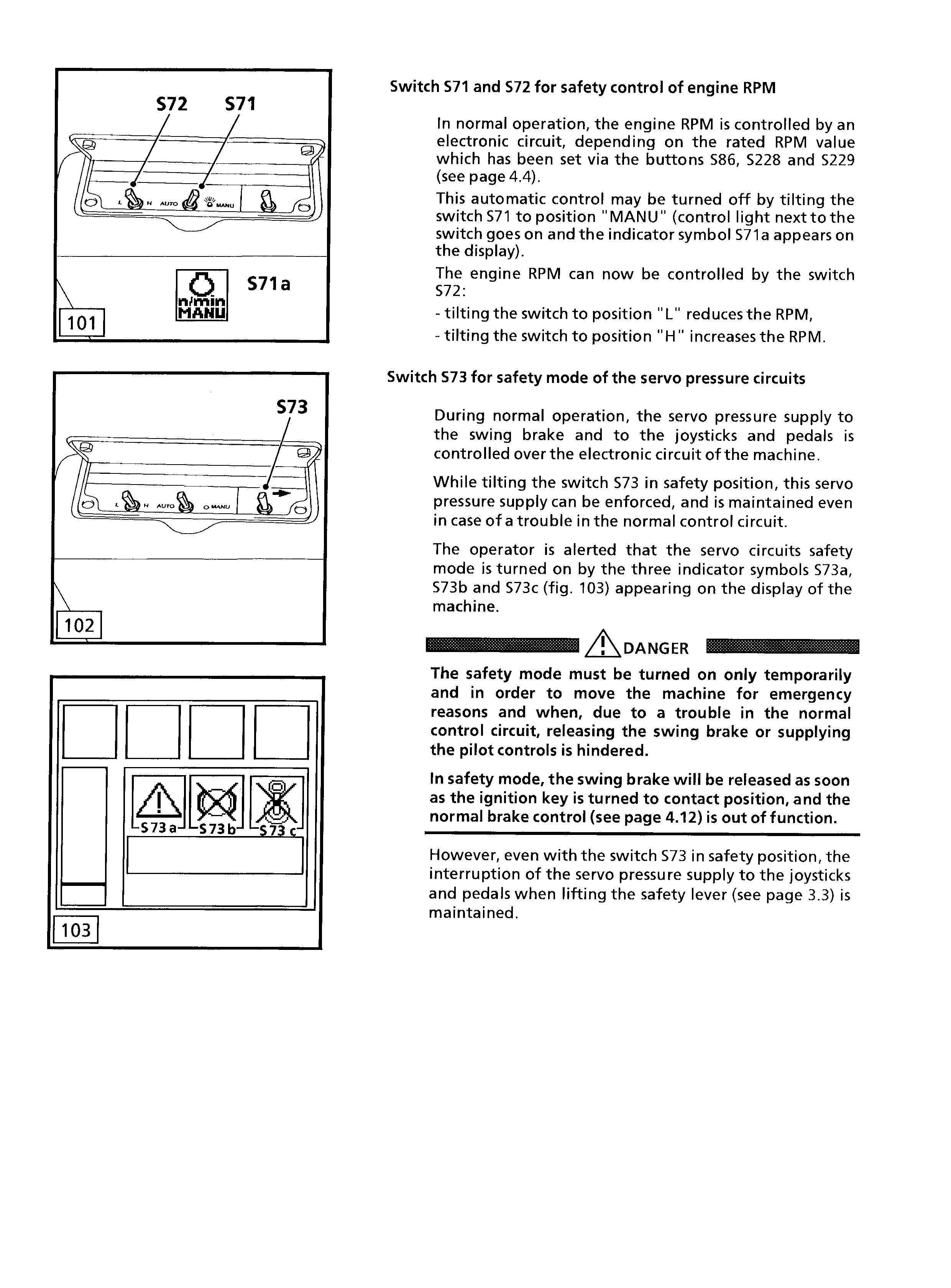
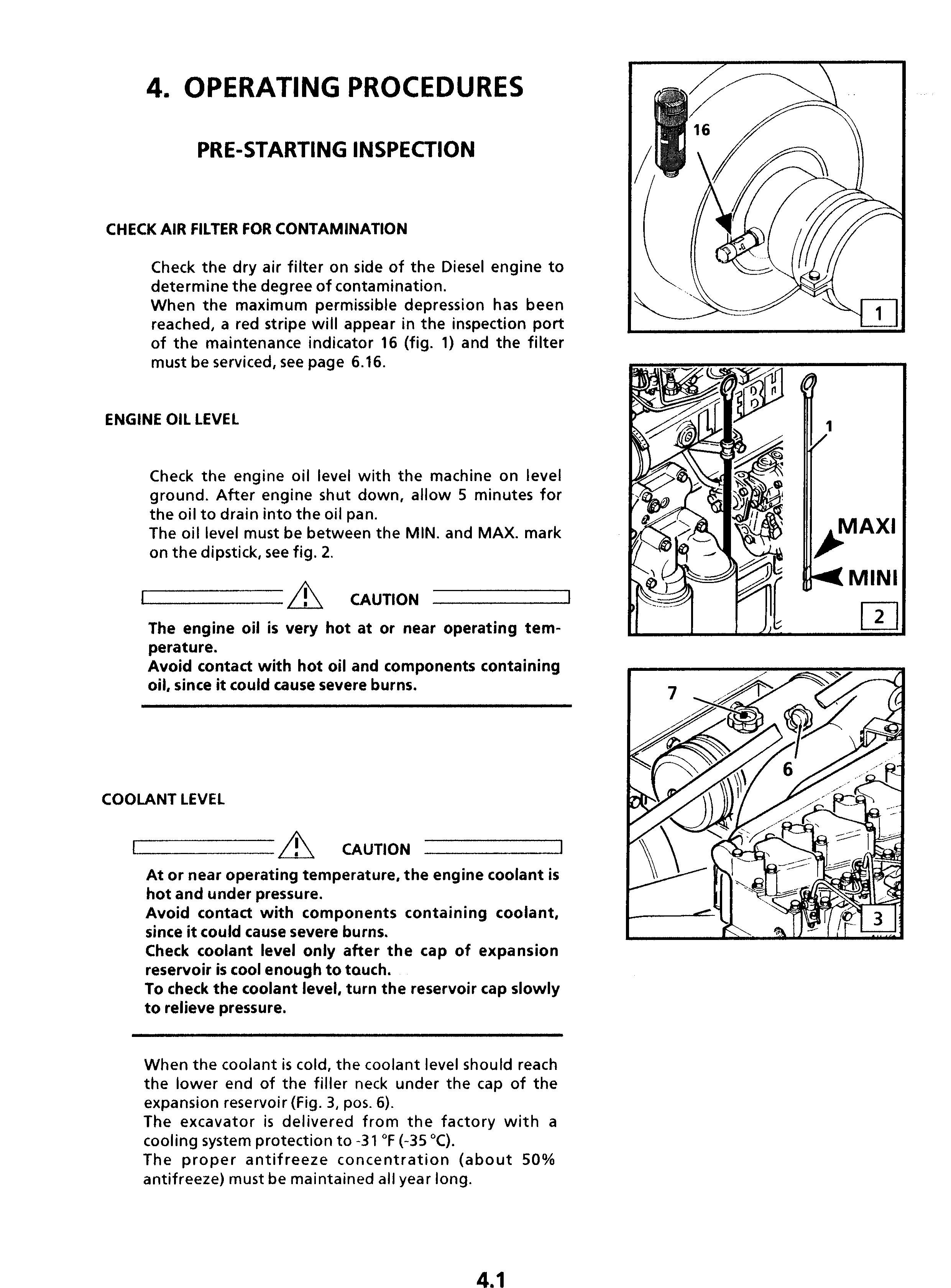
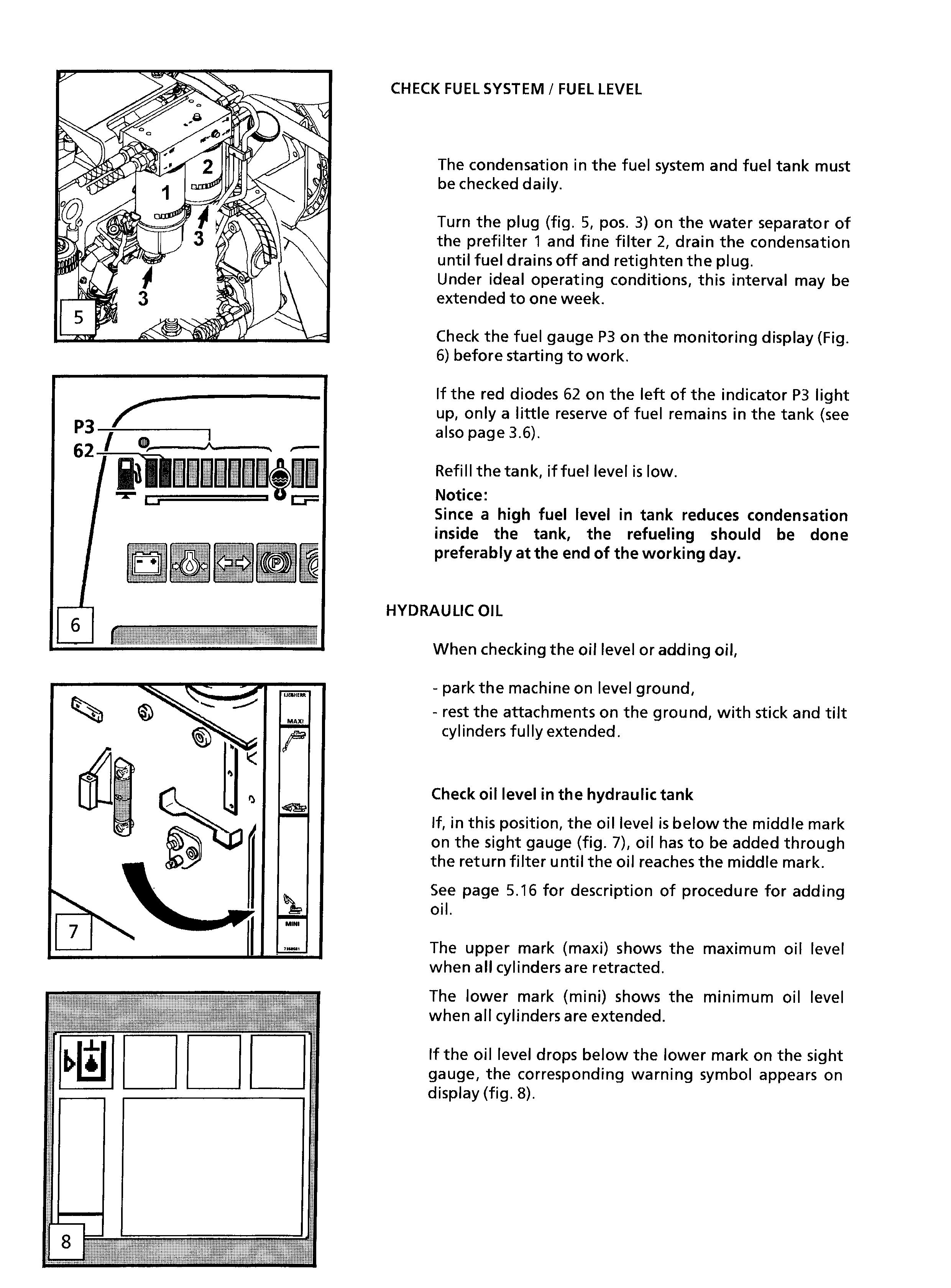
Machine Start Up Safety
Before excavator start up, perform a thorough walk around inspection.
Visually inspect the excavator, look for loose bolts, cracks, wear, any leaks and any evidence of vandalism.
Never start or operate an unsafe excavator.
Report all defects to your foreman or supervisor and make sure they are corrected immediately.
Make sure all covers and doors are closed and all warning decals are on the machine.
Make sure all windows, as well as inside and outside mirrors are clean, and secure all doors and windows to prevent any unintentional movement.
Be certain that the area surrounding the excavator is free of other personnel, and that no one is working on or under the excavator before starting the engine.
and controls, the inside and outside mirror, the armrests and fasten and adjust the seat belt. Be certain that all controls can be reached comfortably.
All noise protection devices on the machine must be functional during operation.
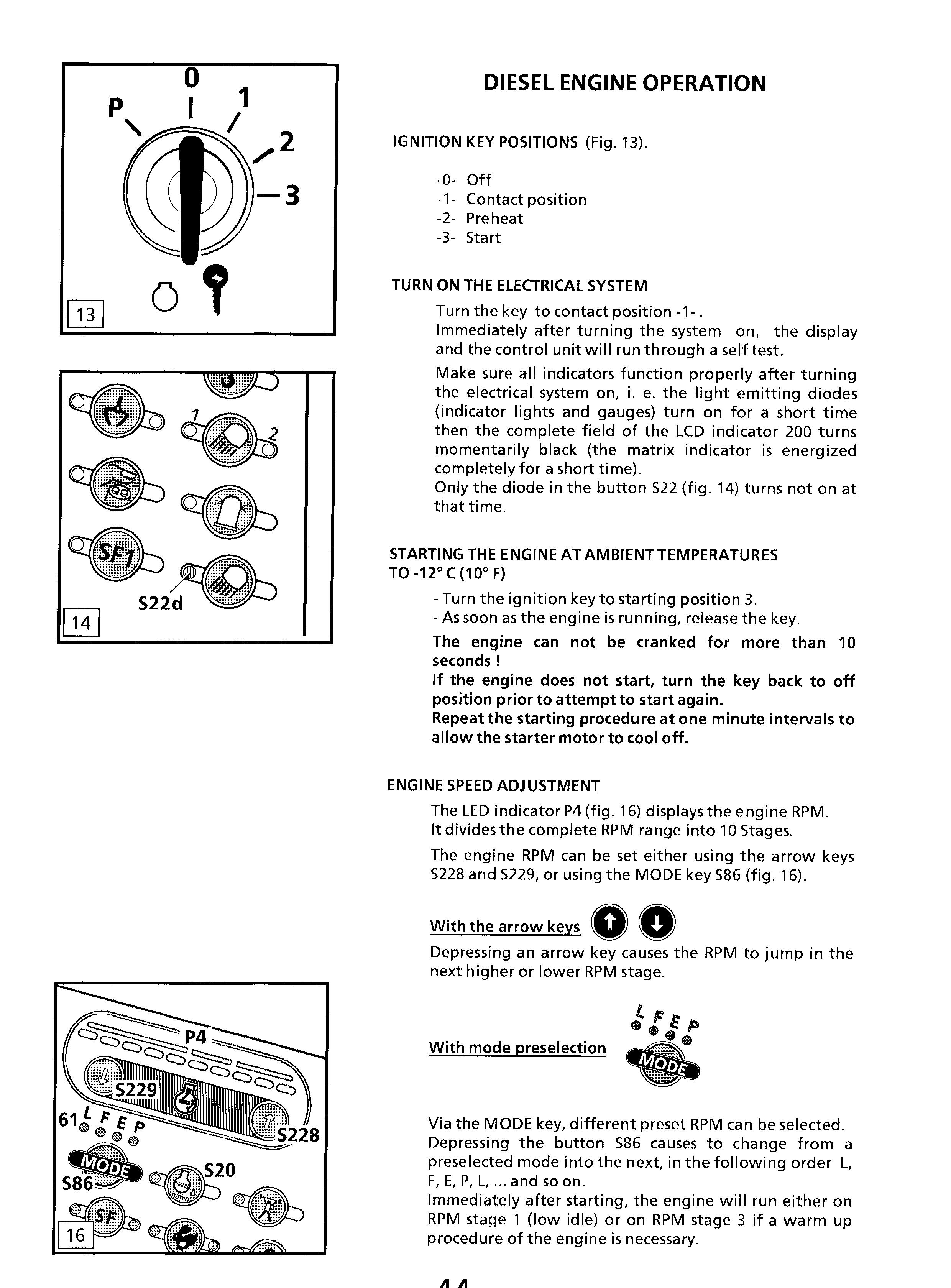
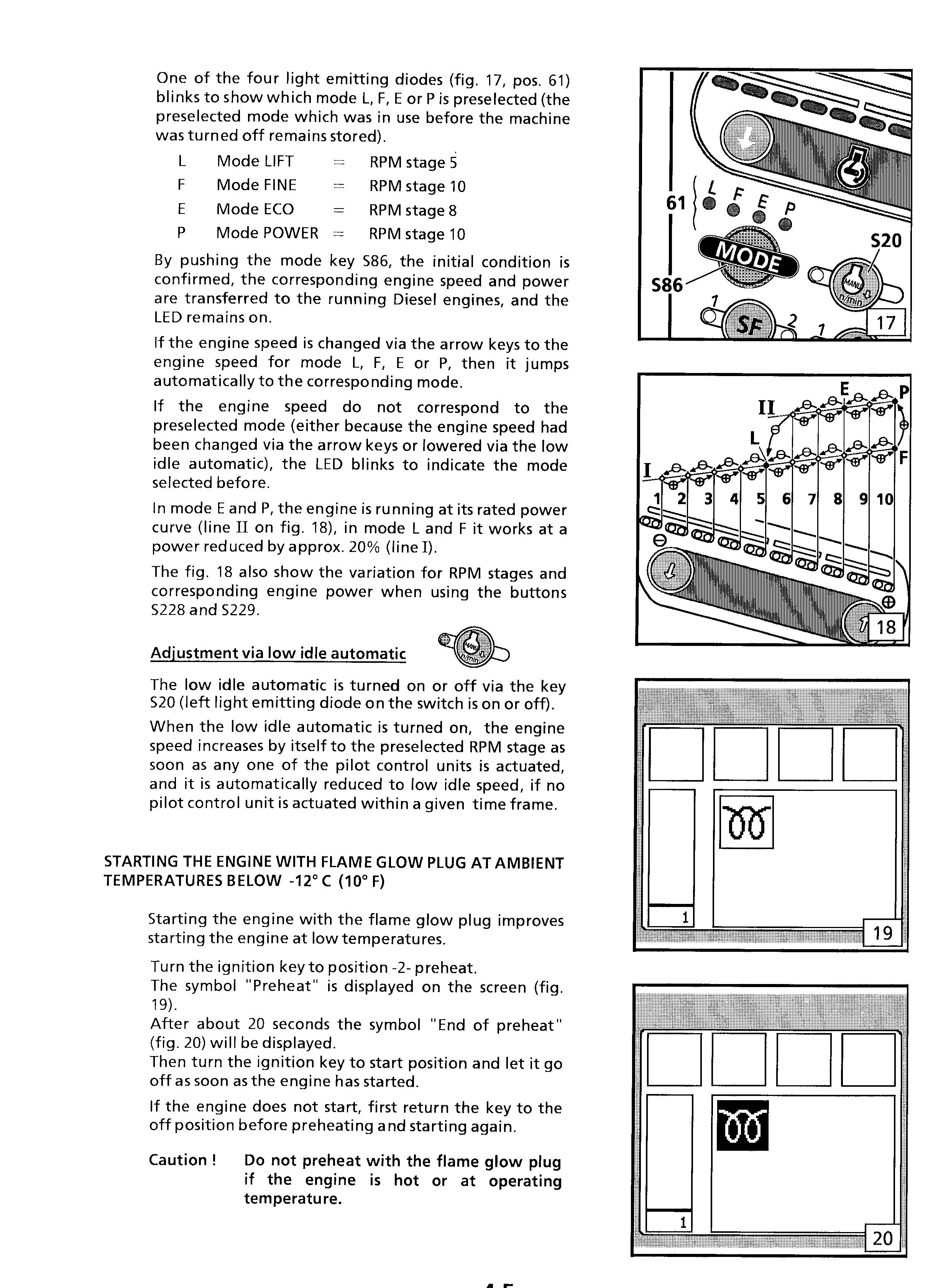
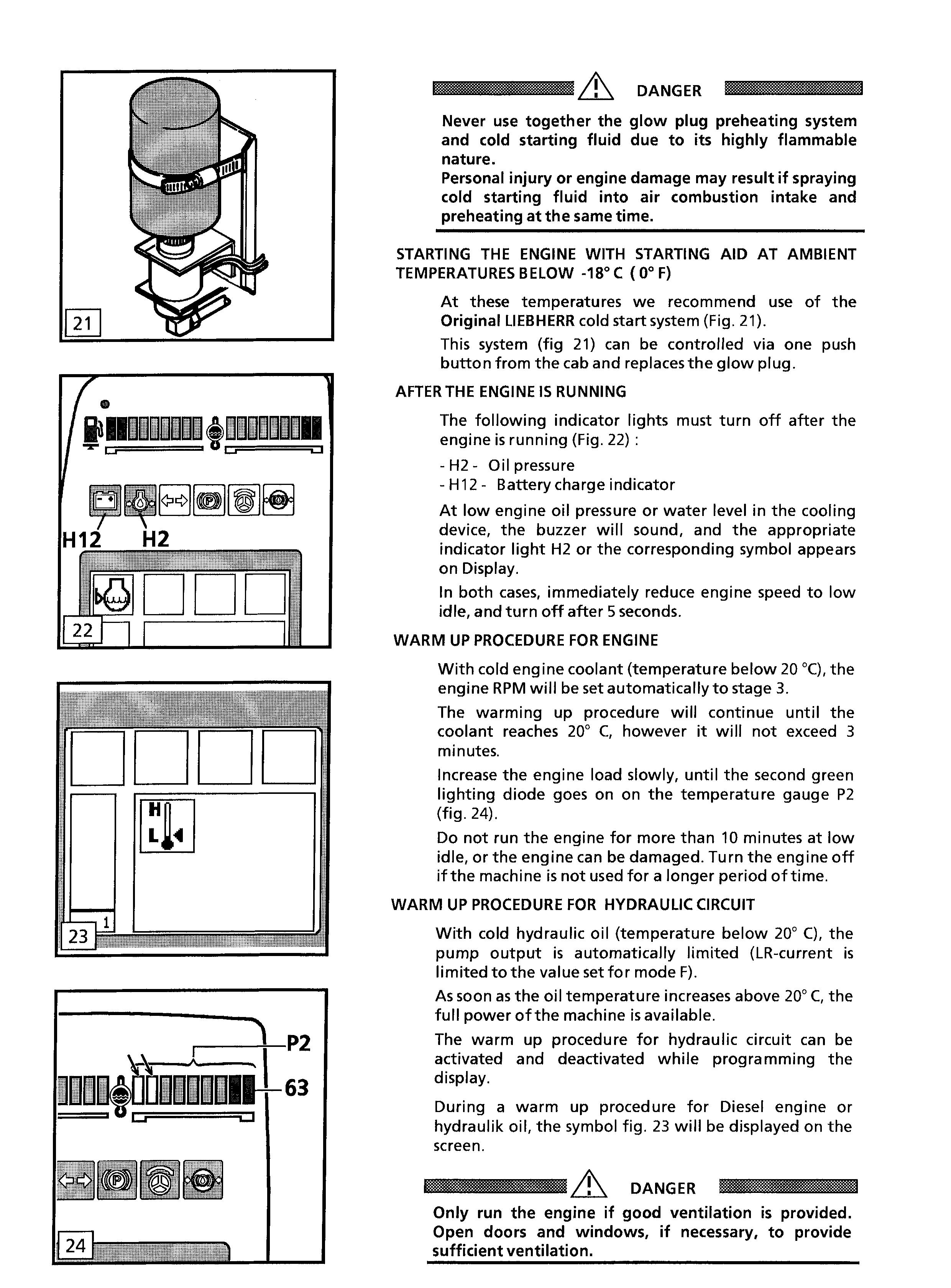
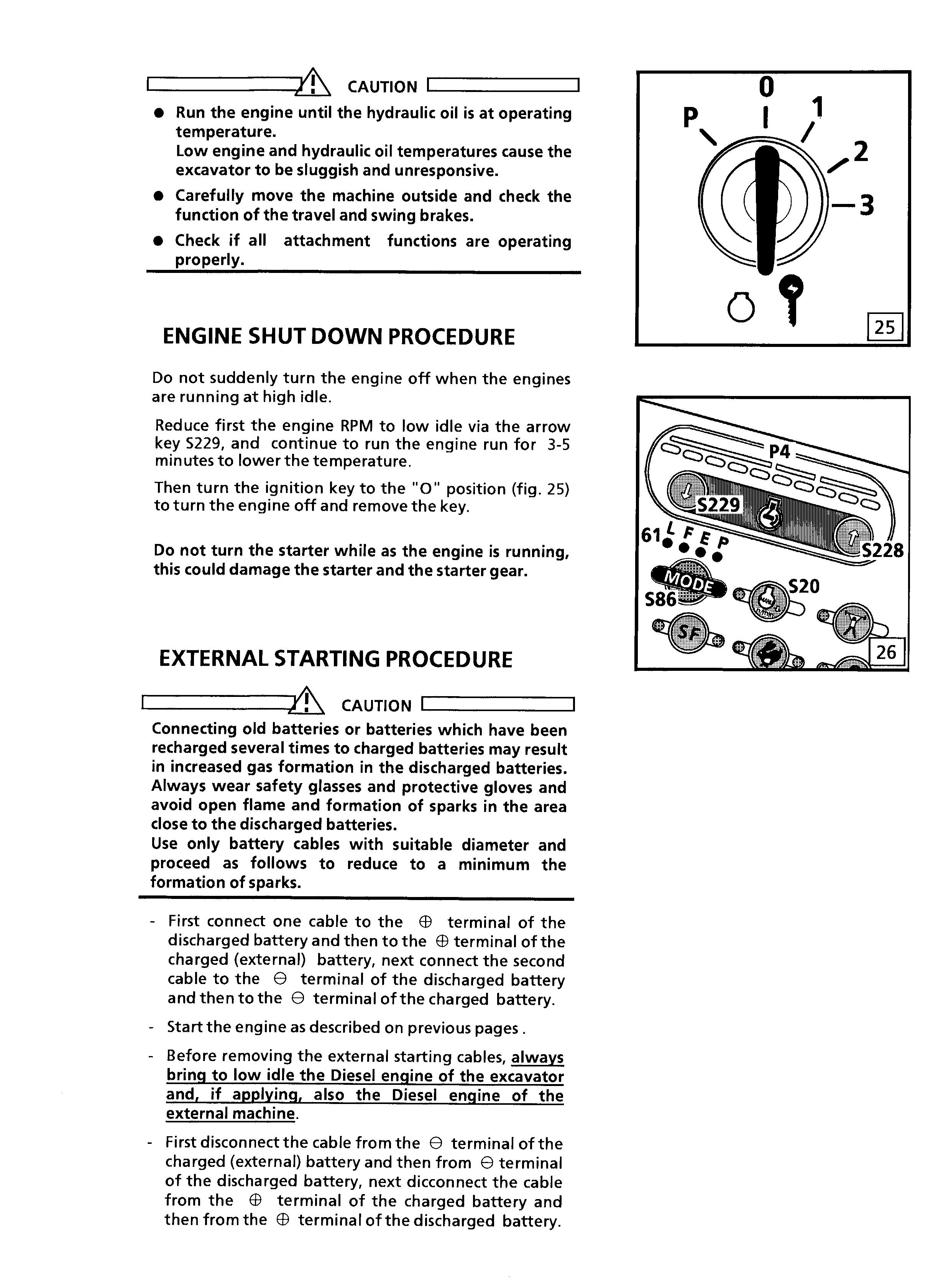
Machine Operating Safety
Familiarize yourself with job site rules. Be informed about traffic and hand signals and safety signs. Ask who is responsible for signalling. Check your surrounding for any obstacles in the working and movement range, check the load carrying capacity of the terrain, and secure the job site to shield it from any public highway traffic. Rope off the working area of the machine and install the necessary signs to forbid any non authorized person entering the area.
Always keep a safe distance from overhangs, walls, drop offs, and unstable ground.
Be alert of changing weather conditions, bad or insufficient visibility and of changing ground conditions.
Be alert for utility lines, check the location of underground cables, gas and water lines, and work especially careful in that vicinity. If necessary and/ or if required, call local authorities to mark the location, and take precaution against contact with underground utilities.
Keep sufficient distance to electrical lines. When working in the vicinity of high voltage electrical lines, keep proper distance to assure that the attachment does not come close to the lines. DANGER! You must inform yourself about safe distances. Preferably have the electrical lines de-energized (and lockout / tagged out according to the regulations applicable on the job-site) each time it is possible, and in any case if the closeness of the working area make it necessary.
In case you do touch a high voltage line by accident, proceed as follows:
- do not leave the machine,
- move the machine, if possible, from the danger zone until you obtain sufficient distance, - warn any personnel in the vicinity not to come close to the excavator and not to touch it, - instruct or initiate that someone turns off the voltage.
- Do not leave the machine until you are absolutely sure that voltage in the line, which had been touched or damaged, has been turned off! Before moving the machine, make sure that the attachments and equipment is secured properly to avoid accidents.
When travelling on public roads, make sure to observe traffic regulations, and make sure that the machine meets federal and local public highway standards.
Always turn on the lights if visibility is bad or if you are still working during dusk. Never allow other personnel on the excavator. Operate the excavator only while seated and with the seat belt fastened, if installed. Report any problems or needed repairs to your foreman or supervisor and make sure they are corrected immediately. is still moving.
Do not move the excavator until you are certain that no one is endangered by moving the excavator.
On machines without negative brakes check the brake system before starting to work, as outlined in the Operation and Maintenance Manual.
Never leave the machine unattended (within view of machine), with the engine running.
When moving the excavator, keep the uppercarriage in lengthwise direction and keep the load as close as possible to the ground.
Prevent any working movements, which could tip the machine over. If the excavator begins to tip or slip on a grade, immediately lower the attachment and load to the ground and turn the excavator facing downhill.
If possible, always operate the excavator with the attachment positioned uphill or downhill, never sideways.
Always travel slowly on rough or slippery ground and on slopes, and on loose soils.
Always travel downhill at permissible speed, so engine must run at nominal speed, use only the foot pedals to brake and slow down the machine. Never shift during down hill travel, always shift to a lower gear before travelling downhill.
Load an occupied truck only if all safety requirements are fulfilled, notably in order to protect the truck operator.
For demolition work, clearing, crane operation, etc. always use the appropriate protection device designed for this specific application.
If operating in visually obstructed terrain or whenever necessary, have another person guide you. Always have only one person signal you. Allow only experienced persons to attach loads or to guide operators. The guide must be visible by the operator and / or must be in voice contact with him.
Depending on the attachment combination, it is possible for the bucket teeth to hit the cab, the cab protection or the boom cylinders. Be very careful when the bucket teeth get in this range to prevent any damage.
In case of a thunderstorm:
- lower the attachment to the ground and if possible anchor the digging tool into the soil.
- leave the cab and move away from the machine before the storm breaks out. Otherwise, you must stop the excavator, turn off the radio and keep inside the closed cab until the end of the storm.
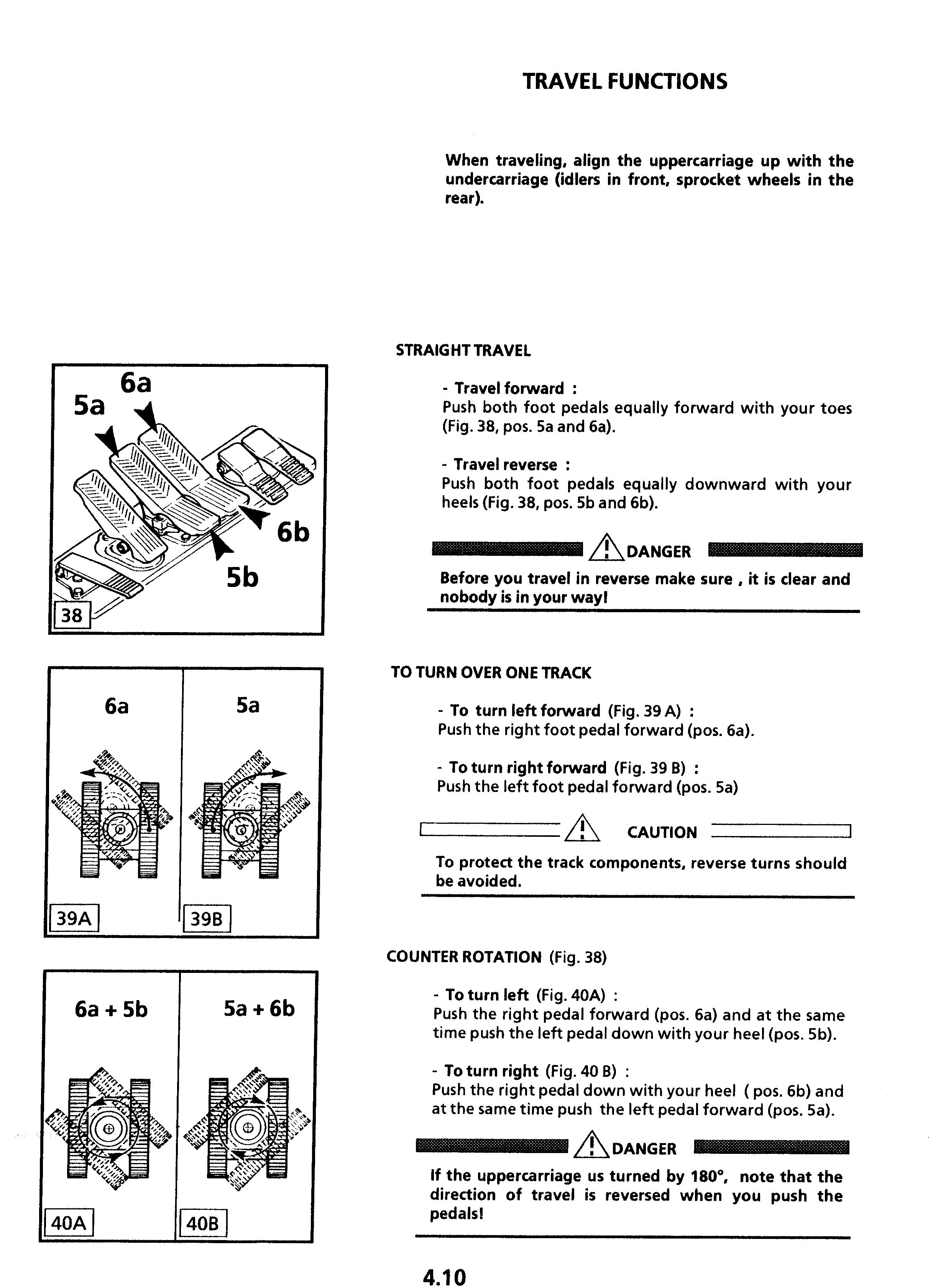
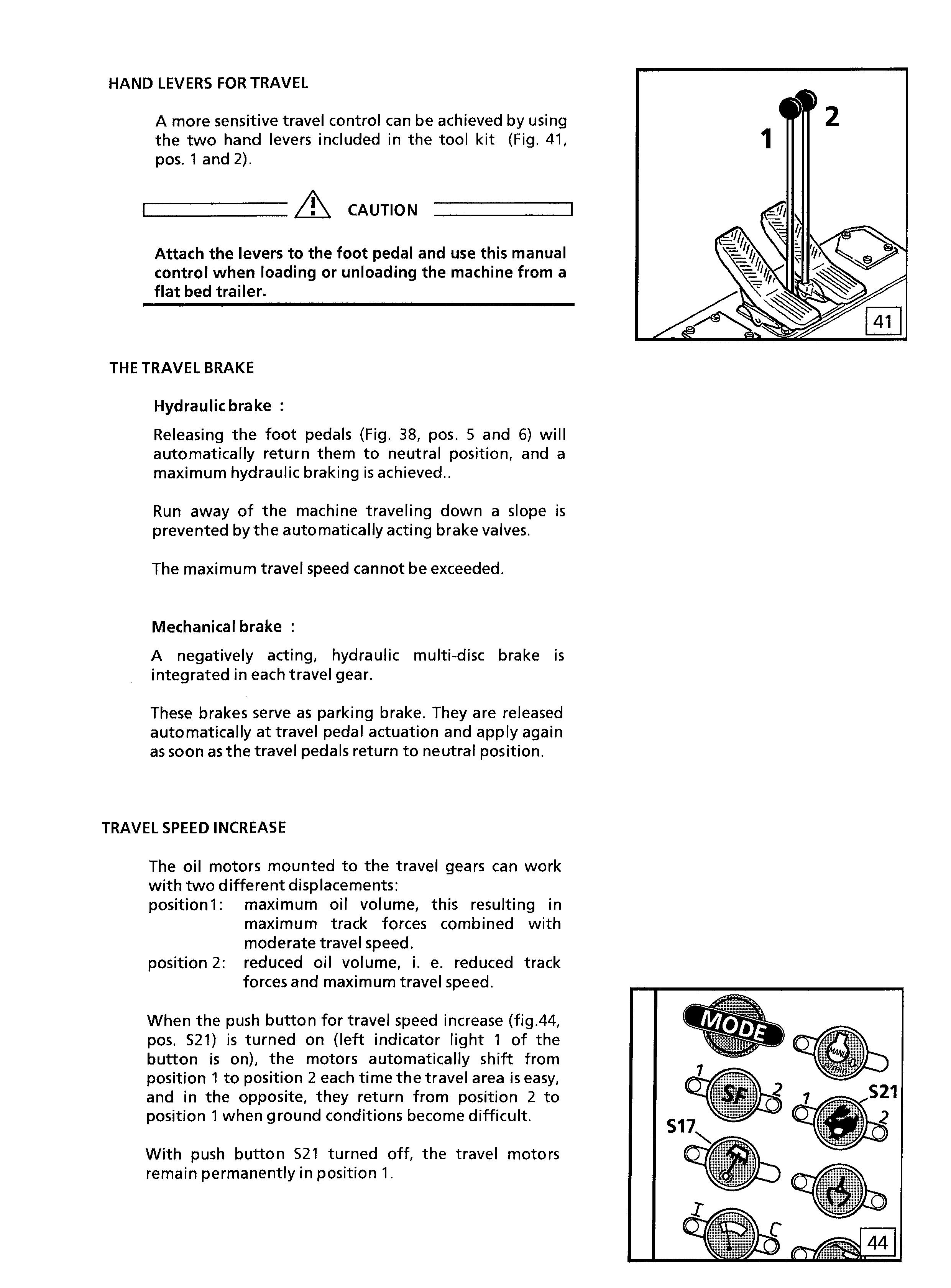
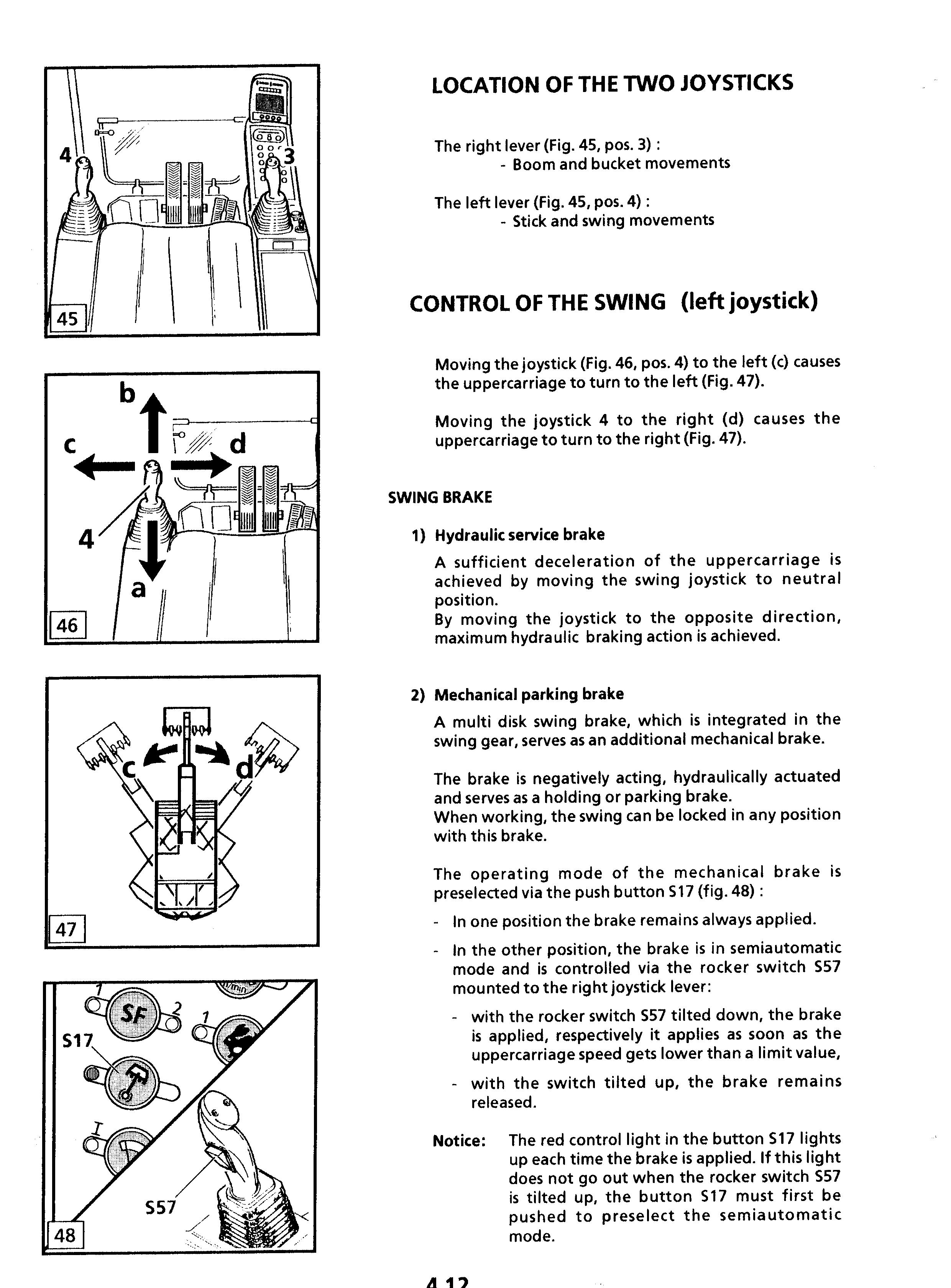
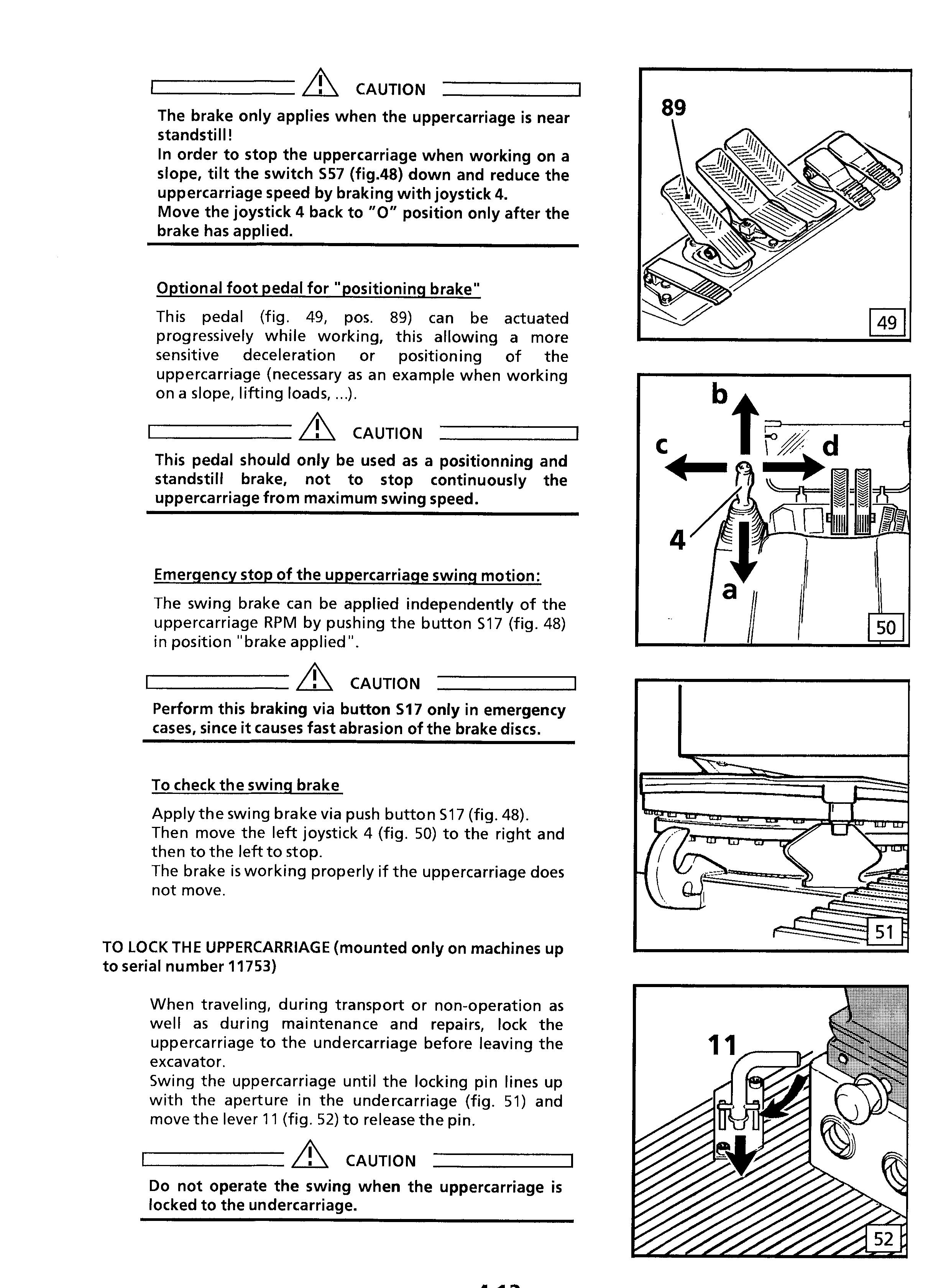
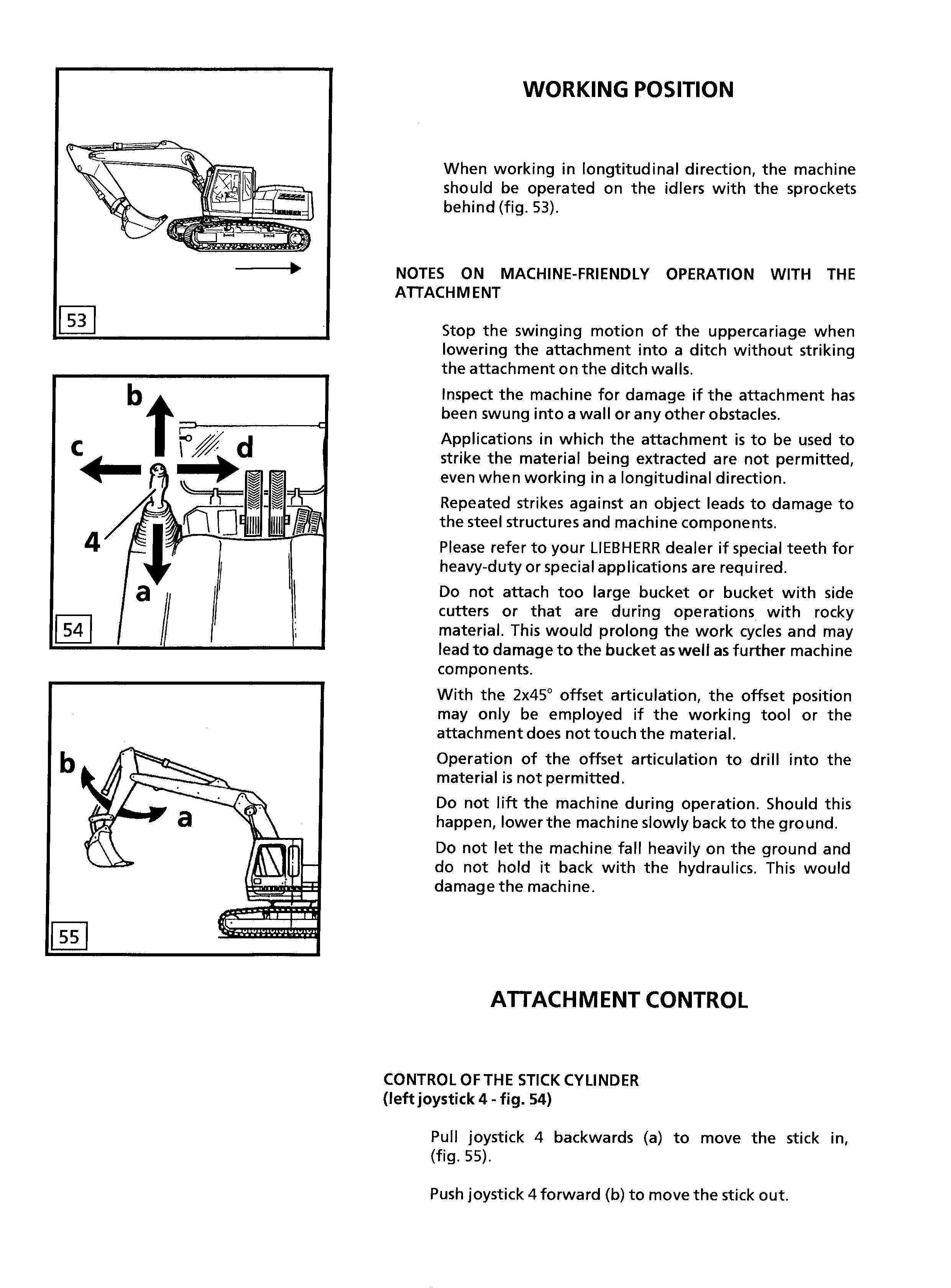
CONTROL OF BOOM CYLINDER
(right joystick 3 - fig.57)
Push joystick 3 forward (g) to lower the attachment (fig.58).
Pull joystick 3 backward (h) to lift the attachment.
CONTROL OF THE BUCKET OR GRAPPLE CYLINDER
(right joystick 3 - fig. 57)
Push joystick 3) to the left (e) to tilt the bucket in or close the grapple (fig. 58).
Push joystick 3 to the right (f) to tilt the bucket out or open the grapple.
Danger
Never allow anybody to guide the grapple by hand !
CONTROL OF A SPECIAL EQUIPMENT (TELESCOPIC STICK, PULLING DEVICE, ... )
The control of special equipments such as telescopic stick (fig. 59A), pulling device (fig. 59B), hydraulic adjustable boom, ... is achieved using the two pedals, 7c and 7d (fig. 61).
For special equipments with two hydraulic cylinders, the second cylinder is controlled via the pedals 7a and 7b (fig.61) of the right pilot control.
If in case of an additional equipment having several hydraulic users, the right pedals 7a and 7b are used to control two different movements, the commutation from one movement into the other is obtained while tilting the rocker switch S55 in the left joystick handle.
Caution
Auxiliary control units can have various functions. Always check their functions when starting up the machine.
Depending on the function and on the type of the special tool, it may be necessary, before attempting to control the special equipment, to confirm the corresponding choice of pump parameters, using the menu "Set Option" of the display.
CONTROL OF HYDRAULIC HAMMER (optional equipment)
The hydraulic hammer is actuated via the pedal 7d of the left pilot control (fig. 61).
Notice:
The operation of a hydraulic hammer requires the previous setting of the correct option which have been allocated to use of this hammer, using the menu "Set Option" of the display (fig. 62). Normally the designation appearing in the lower right corner of the screen must correspond to the definition of the installed hammer.
In case of a doubt, contact your supervisor to obtain this information.
Caution
The choice of the option in the menu "set option" determines pressure and oil flow adjustment in the hydraulic circuit.
A wrong choice of the option could lead to damage or unsatisfactory operation of the additional equipment. The choice of the option does neither have an influence upon the allocation of the pedals, nor lead, to a switchingoff of the pedal function.
For operation with a hydraulic hammer:
The hydraulic hammer must be selected with particular care. When using a hydraulic hammer not permitted by LIEBHERR, steel structures or the other machine components can become damaged.
Before beginning breaking tasks, position the machine on firm and level ground..
Use a hydraulic hammer designed exclusively for breaking stone, concrete and other breakable materials.
Only operate the hydraulic hammer in the longitudinal direction of the machine and with the windshield closed or with a front protective grid.
Ensure during hammer operation that no cylinder is entirely extended or retracted and that the stick is not in the vertical position.
In order to avoid damages to the machine, try not to break stone or concrete while performing retraction and extension motions of the hydraulic hammer.
Do not apply the hydraulic hammer uninterrupted for more than 15 secs. at a time to the same place. Change the breaking point. Too long uninterrupted operation of the hydraulic hammer leads to an unnecessary overheating of the hydraulic oil.
Do not use the drop force of the hydraulic hammer to break stone or other materials. Do not move obstacles with the hydraulic hammer. Misuse of this nature would damage both the hammer and the machine.
Do not use the hydraulic hammer to lift objects.